ANK DAC5.1 Signature Instructions for use

DAC5.1 Signature
Construction Manual
Version 2.0 Jan 2016
audionotekits@rogers.com
1-613-822-7188

Table of Contents
1 - INTRODUCTION..............................................................................................1
2 - ABOUT ANKITS...............................................................................................2
3 - EQUIPMENT ...................................................................................................3
4 - TIPS AND SUGGESTIONS.................................................................................4
5 - SKILLS / PREREQUISITES .................................................................................5
5.1 HARDWARE/MECHANICAL................................................................................................... 5
5.2 WIRE –STRIPPING /TINNING................................................................................................ 6
5.3 OHM METER /RESISTORS ................................................................................................... 6
5.4 SOLDERING ...................................................................................................................... 6
5.5 CAPACITOR ORIENTATION .................................................................................................... 6
5.6 VOLTAGE CHECKS .............................................................................................................. 7
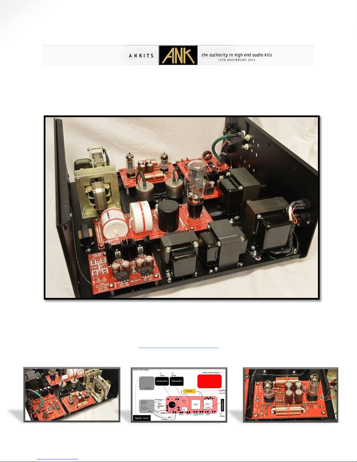
6 - DAC5.1 HISTORY & TECHNICAL OVERVIEW.....................................................8
7 - DAC5.1 ASSEMBLY..........................................................................................9
7.1 INSTALL THE FEET............................................................................................................... 9
7.2 INSTALL THE DAC5.1 POWER SUPPLY.................................................................................... 10
7.3 INSTALL THE MAINS TRANSFORMERS .................................................................................... 12
7.3.1 Securing the PCB onto the chassis..............................................................................................................12
7.3.2 Connecting the White wires .......................................................................................................................13
7.3.3 Connecting the White/Grey wires..............................................................................................................14
7.3.4 Connecting the Black wires ........................................................................................................................15
7.3.5 Connecting the Black/Grey wires ...............................................................................................................16
7.3.6 Connecting the jumper cables 120V ONLY.................................................................................................17
7.3.7 Connecting the jumper cables 240V ONLY.................................................................................................18
7.3.8 Connecting the PCB to the Rocker switch ..................................................................................................19
7.3.9 Connecting the Rocker switch to the IEC....................................................................................................20
7.3.10 Connecting the IEC’s to the ground..........................................................................................................21
7.3.11 Final schematics of the 120V and 240V circuits .......................................................................................22
7.3.12 Mount the Mains Transformers into the chassis......................................................................................24
8 - FILAMENT BOARD ........................................................................................25
8.1 BUILDING THE FILAMENT BOARD ......................................................................................... 26
8.1.1 Mount the Filament board into the Chassis...............................................................................................28
8.2 POWER SUPPLY PCB ........................................................................................................ 29
8.2.1 Install a bridge ...........................................................................................................................................31
8.2.2 Install the 8-Pin Valve Base........................................................................................................................32
8.2.3 Install the White EVO Film Caps & the black 47uf TUBE cap .....................................................................33

9 - SUPER REGULATOR BOARD ..........................................................................34
9.1 INSTALL THE RESISTORS ..................................................................................................... 36
9.2 INSTALL THE FIRST CAPACITORS ........................................................................................... 37
9.3 INSTALL THE BRIDGE RECTIFIERS .......................................................................................... 38
9.4 INSTALL THE REGULATORS AND HEAT SINKS ............................................................................ 39
9.5 INSTALLING THE REMAINING CAPACITORS ............................................................................... 40
9.6 FINAL PRODUCT .............................................................................................................. 41
10 - DAC5.1 INTERWIRING.................................................................................44
10.1 WIRING THE PTL4 TRANSFORMER TO THE POWER SUPPLY PCB ................................................. 48
10.2 WIRING THE PTDAC4-1 TRANSFORMER TO THE FILAMENT BOARD ............................................ 49
10.3 WIRING THE CHOKE TRANSFORMERS TO THE POWER SUPPLY PCB.............................................. 51
10.4 WIRING THE 15K MILLS RESISTOR TO THE POWER SUPPLY PCB ................................................. 52
10.5 WIRING THE SUPER REGULATOR BOARD .............................................................................. 53
11 - TESTING THE POWER SUPPLY .....................................................................55
11.1 INSTALL THE 5U4G EH TUBE IN POSITION IN THE 8PIN SOCKET .................................................. 57
12 - DIGITAL BOARD..........................................................................................59
12.1 CONNECTING THE COAXIAL CABLE FROM SPDIF TO THE CON1 PORT .......................................... 60
12.2 MOUNTING THE BOARD INTO THE CHASSIS ........................................................................... 61
12.3 WIRING TO THE SUPER REGULATOR BOARD .......................................................................... 67
13 - ANALOG LINE BOARD .................................................................................69
13.1 INSTALLING THE JUMPERS ................................................................................................ 72
13.2 INSTALL THE COMPONENTS............................................................................................... 73
13.2.1 AudioNote Tantalum Resistors.................................................................................................................73
13.2.2 Valve Bases ..............................................................................................................................................74
13.2.3 4 x 470uf ..................................................................................................................................................75
13.2.4 VCAP Film Caps ........................................................................................................................................75
13.3 WIRING TO THE FILAMENT BOARD ..................................................................................... 77
13.4 WIRING CONNECTIONS TO THE POWER SUPPLY ..................................................................... 78
14 - I/V TRANSFORMER INSTALLATION .............................................................79
14.1 CONNECTING I/V TO DIGITAL BOARD.................................................................................. 80
14.2 CONNECTING I/V TO LINE BOARD ...................................................................................... 81
15 - TRIPLE C CORE OUTPUT TRANSFORMERS ...................................................83
15.1 MOUNTING INTO THE CHASSIS .......................................................................................... 84
15.2 OUTPUT TRANSFORMER (CC-410) CONNECTIONS TO THE POWER SUPPLY .................................... 85
16 - REAR OF DAC5.1 CHASSIS CONNECTIONS ...................................................86

17 - WIRING THE OUTPUT TRANSFORMER SECONDARY’S .................................89
18 - FINAL CHECKS – DAC5.1..............................................................................91
18.1 POWER UP &TESTING ................................................................................................... 91
19 - INSTALLING THE ROTARY ON/OFF SWITCH ( OPTIONAL )............................92
19.1 FRONT AND REAR FACEPLATES .......................................................................................... 95
20 - FINAL THOUGHTS .......................................................................................96
21 - DAC5.1 APPENDIX ......................................................................................97

1 -
Introduction
Congratulations on your purchase of the DIY version of the ANKits DAC5.1. This is very high
end and sophisticated piece of audio equipment that will surely become the showpiece of your
sound system! We are excited you have chosen to join us on the path of audio superiority, and
thus, we have created this manual to help guide you through each step of the assembly process
with as much detail and clarity possible. To facilitate the build process, the manual has been
divided into several chapters, each focusing on a separate aspect of the system; follow through
the chapters in order and we guarantee not only a problem free experience, but a pleasant
time doing so.
If you are new to building kits, or if at any time you feel as though you need help or advice,
feel free to contact us and we will do whatever it takes to get you on the right track.
Enjoy!
1
Table of contents
Other ANK Media Converter manuals
Popular Media Converter manuals by other brands

H&B
H&B TX-100 Installation and instruction manual

Bolin Technology
Bolin Technology D Series user manual

IFM Electronic
IFM Electronic Efector 400 RN30 Series Device manual

GRASS VALLEY
GRASS VALLEY KUDOSPRO ULC2000 user manual

Linear Technology
Linear Technology DC1523A Demo Manual

Lika
Lika ROTAPULS I28 Series quick start guide

Weidmuller
Weidmuller IE-MC-VL Series Hardware installation guide

Optical Systems Design
Optical Systems Design OSD2139 Series Operator's manual

Tema Telecomunicazioni
Tema Telecomunicazioni AD615/S product manual

KTI Networks
KTI Networks KGC-352 Series installation guide

Gira
Gira 0588 Series operating instructions

Lika
Lika SFA-5000-FD user guide