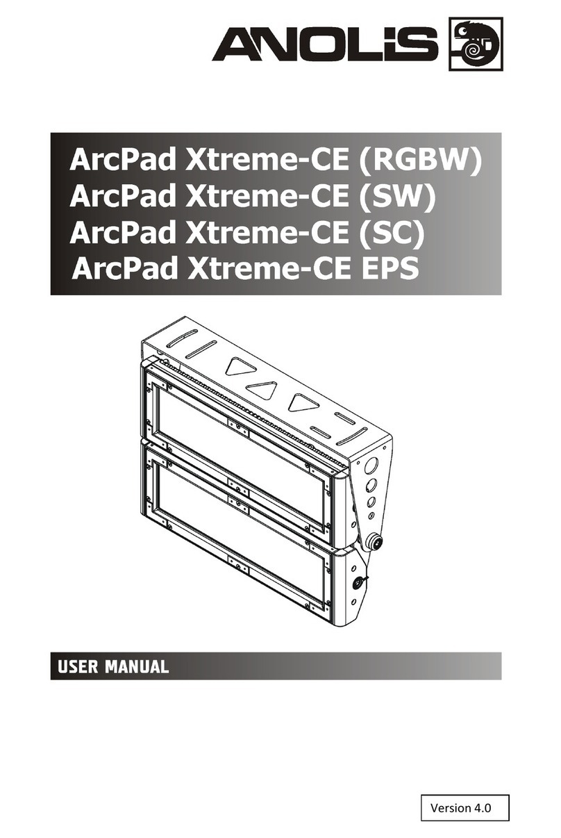
Anolis ArcPad Xtreme User manual

Version
3
.
0

ArcPad Xtreme
2
Table of contents
1. Safety instructions ...................................................................................................................................................... 3
2. Fixture exterior view ................................................................................................................................................... 4
3. Insta ation .................................................................................................................................................................. 5
3.1 Mounting the fixture ............................................................................................................................................ 5
3.2 Connection to the mains ...................................................................................................................................... 6
3.3 Insta ation of the barn-doors, top/ha f top hats ................................................................................................. 7
3.4 Setting and contro ............................................................................................................................................... 7
3.5 DMX 512 connection ............................................................................................................................................ 8
3.6 Master/s ave connection ...................................................................................................................................... 8
3.7 Stand-a one operation .......................................................................................................................................... 8
4. ArcPad Xtreme (RGBCW) - DMX protoco ................................................................................................................. 10
5. Contro menu map .................................................................................................................................................... 12
6. Fixture menu ............................................................................................................................................................. 14
6.1 Fixture Address ................................................................................................................................................... 16
6.2 Fixture information ............................................................................................................................................. 16
6.3 Persona ity .......................................................................................................................................................... 17
6.4 Manua mode ...................................................................................................................................................... 18
6. 5 Test sequences................................................................................................................................................... 18
6.6 Stand-a one setting ............................................................................................................................................. 18
6.7 Specia functions ................................................................................................................................................. 19
7. RDM .......................................................................................................................................................................... 21
8. Error and information messages .............................................................................................................................. 22
9. Technica specifications ............................................................................................................................................ 23
10. C eaning and maintenance ..................................................................................................................................... 26
11.Apendix .................................................................................................................................................................... 27
11.1 ArcPad Xtreme EPS ........................................................................................................................................... 27

ArcPad Xtreme
3
FOR YOUR OWN SAFETY, PLEASE READ THIS USER MANUAL CAREFULLY
BEFORE POWERING OR INSTALLING YOUR ArcPad Xtreme !
Sa e it for future reference.
This device has eft our premises in abso ute y perfect condition. In order to maintain this condition and to ensure a
safe operation, it is abso ute y necessary for the user to fo ow the safety instructions and warning notes written in
this manua .
The manufacturer wi not accept iabi ity for any resu ting damages caused by the non-observance of this manua
or any unauthorized modification to the device.
P ease consider that damages caused by manua modifications to the device are not subject to warranty.
1. Safety instructions
DANGEROUS VOLTAGE CONSTITUTING A RISK OF ELECTRIC SHOCK IS PRESENT WITHIN THIS UNIT!
Make sure that the avai ab e vo tage is not higher than stated on the rear pane of the fixture.
This fixture shou d be operated on y from the type of power source indicated on the marking abe . If you are not
sure of the type of power supp ied, consu t your authorized distributor or oca power company.
A ways disconnect the fixture from AC power before c eaning, removing or insta ing the fuses, or any part.
Do not over oad wa out ets and extension cords as this can resu t in fire or e ectric shock.
Make sure that the power/data cord is never crimped or damaged by sharp edges. Check the fixture and the
power/data cord from time to time.
Do not insta the unit near naked f ames.
During the operation the housing becomes hot (up to 85°C)
Refer servicing to qua ified service personne .
This fixture falls under protection class I. Therefore this fixture has to be connected to a mains socket outlet with
a protective earthing connection.
Do not connect this fixture to a dimmer pack.
LED light emission. Risk of eye injury.
Do not look straight at the fixture´s LEDs during operation. The intense light beam may damage your eyes.
Keep compustib e materia s at east 40 cm away from the fixture.
If the fixture has been exposed to drastic temperature f uctuation (e.g. after transportation), do not switch it on
immediate y. The arising condensation water might damage your device. Leave the device switched off unti it has
reached room temperature.
Do not shake the fixture. Avoid brute force when insta ing or operating the fixture.
The fixture was designed for indoor use and it is intended for professiona app ication on y. It is not for househo d
use.

ArcPad Xtreme
4
When choosing the insta ation spot, p ease make sure that the fixture is not exposed to extreme heat or dust.
Avoid using the unit in ocations subject to possib e impacts.
The fixture body never must be covered with c oth or other materia s.
On y operate the fixture after having checked that the housing is firm y c osed and a screws are tight y fastened.
Make sure that the area be ow the insta ation p ace is b ocked when rigging, derigging or servicing the fixture.
Do not b ock the front objective LEDs with any object when the fixture is under operation.
The fixture becomes very hot during operation. A ow the fixture to coo approximate y 40 minutes prior to
manipu ate with it.
Operate the fixture on y after having fami iarized with its functions. Do not permit operation by persons not
qua ified for operating the fixture. Most damages are the resu t of unprofessiona operation!
Do not attempt to dismant e or modify the unit.
P ease consider that unauthorized modifications on the fixture are forbidden due to safety reasons!
P ease use the origina packaging if the fixture is to be transported.
If this device wi be operated in any way different to the one described in this manua , the product may suffer
damages and the guarantee becomes void. Furthermore, any other operation may ead to dangers ike short-
circuit, burns, e ectric shock etc.
2. Fixture exterior view
1. LED modu es
5. Mounting bracket
2. Ti t- ocks for LED modu es 6. Contro unit
3 Ti t- ock for both LED modu es 7. LED modu es supp y
4. Power/data cab e

ArcPad Xtreme
5
3. Installation
3.1 Mounting the fixture
Ensure that the structure (truss, wall) to which you are attaching
the fixture is secure.
The ArcPad Xtreme can be arranged in any position orientation. The ArcPad Extreme a ows to adjust its LED
modu es to the desired position either both modu es together (by means of the A en key 14 ) or each modu e
separate y (by means of the se f- ocking screws).
Danger of injury! Two workers ha e to handle with the fixture including adjusting the LED modules to
the desired position. The LED modules are ery hea y.
Five s ots in the mounting bracket serve for mounting the fixture on non-f ammab e f at surface.
Caution: Overhead insta ation requires experience. Fixtures may cause severe injuries when crashing down! If you
have doubts concerning the safety of a possib e insta ation, do not insta the device and consu t insta ation with
an expert.

ArcPad Xtreme
6
3.2 Connection to the mains
Fixtures must be installed by a qualified electrician in accordance with all national
and local electrical and construction codes and regulation
The ArcPad Xtreme is equiped with a 5-cored power/data cab e. The 3 cores serve for the power supp y and next
2 shie ded cores are intended for DMX connection.
The power cores are co oured according to the fo owing tab e.
Core
Connection
Plug Terminal Marking
B ack
Live
L
B
ue
Neutra
N
Ye ow/Green
Earth
This device falls under class one and must be grounded!
The data cores (DMX) are co oured according to the tab e:
Core
Connection
Red
Data +
White
Data
-
Shie ding
Data
ground
The power/data cab e is connected to a junction box as shown on the picture be ow.

ArcPad Xtreme
7
3.3 Installation of the barn doors, top/half top hats
You can insta barn-doors or top hats to better define i uminated surface.
Before insta ing the equipment disconnect the fixture from the mains.
1. Fit the barn-doors modu e (1) or top/ha f top hat (2) on the LED modu e (4) and fasten it by means of the
12 screws (3) as shown on the picture be ow.
2. Repeat the same steps for the second LED modu e of the fixture.
ever close the barn-doors during fixture operation!
3.4 Setting and control
For setting DMX address, se ecting DMX mode and for another settings you need either Robe Universa Interface
or the RDM Communicator. P ease see the Robe Universa Interface or RDM Communicator user manua s to get
more information about this products. The way, how to connect these interfaces to the DMX data ink is figured
be ow.
OTE: never connect the RDM communicator and the The Robe Universa Interface to the fixture at the same
time.
1.Robe Universal Interface

ArcPad Xtreme
8
2. RDM Communicator
Note: DMX contro er has to be disconnected from the fixture when the RDM communicator is operated.
After addressing and setting fixtures´behaviour you can use the Cyber Arch (after programming it) for stand-a one
operation of fixtures.
3.5 DMX 512 connection
To bui d a DMX chain
1. Connect the DMX output of the contro er direct y with the DMX input of the first fixture in the DMX chain.
2. Connect the DMX output of the first fixture in the DMX chain with the DMX input of the next fixture.
3. A ways connect the DMX output with the input of the next fixture unti a fixtures are connected.
Do not over oad the ink. Max. 32 fixtures may be connected on a DMX ink.
Caution: Terminate the output of the ast fixture with a 120 Ohm resistor wired betwen data (+) and data (-) in
order to ensure the proper transmission on the data ink.
3.6 Master/slave connection
To bui d a master/s ave-chain:
Connect the DMX output of the master fixture in the data chain with the DMX input of the first s ave. A ways
connect output with the input of the next s ave unti a s aves are connected (up to 32 fixtures).
Caution: It is necessary to terminate the input of the master fixture and the output of the ast s ave with a 120 Ohm
resistor in order to ensure the proper transmission on the data ink.
3.7 Stand alone operation
The fixtures on a data ink are not connected to the contro er but can execute pre-set programs which can be
different for every fixture. To set the program to be p ayed, see the "Stand-a one setting" (menu "St.AL.").
"Stand-a one operation" can be app ied to the sing e fixture or to mu tip e fixtures operating synchronous y.

ArcPad Xtreme
9
Synchronous operation of mu tip e fixtures requires that they must be connected on a data ink and one of them is
set as a master (master mode) and the rest as the s aves (s ave mode).
To set the fixture as the master or s ave, see the " Fixture Address " (menu "A001").
On y one fixture can be set as the master.
The master fixture starts simu taneous program start in the other s ave fixtures. A fixtures have a definite,
synchronized starting point when p aying back their programs. The number of running program is the same in a
s aves and depends on the master's choice (menu "St.AL.“). Every fixture runs its program repeated y, starting the
program step No.1 when requested by the master.
Examp e:
If the s ave fixture has a shorter program ength, it wi continuous y repeat its program unti the master fixture
finishes its own program and restarts its program running (s ave 1- prog.step 3 wi not be finished).
If the s ave fixture has a onger program ength, it wi restart at prog. step 1 before it comp etes a its prog.steps
(s ave 2 - prog.step 5 wi not be p ayed)- see the picture be ow.
ote: Disconnect the fixtures from the DMX contro er before master/s ave operating, otherwise data co isions
can occur and the fixtures wi not work proper y!

ArcPad Xtreme
10
4. ArcPad Xtreme (RGBCW) DMX protocol
Version 1.0
Mode/Channel
Value Function Type of control
1
2
*
3
4
5
6
-
1
1
1
-
-
0 - 255
Red LEDs
-
both
LED
modules
Red LEDs saturation contro (0-100%)
proportiona
-
2
2
2
-
-
0 - 255
Green LEDs
-
both
LED m
odules
Green LEDs saturation contro (0-100%)
proportiona
-
3
3
3
-
-
0 - 255
Blue LEDs
-
both
LED
modules
B ue LEDs saturation contro (0-100%)
proportiona
-
-
4
4
-
-
0 - 255
White LEDs
-
both
LED
modules
White LEDs saturation contro (0-100%)
proportiona
-
-
-
-
1
1
0 - 255
Red LEDs
–
LED
module 1
Red LEDs saturation contro (0-100%)
proportiona
-
-
-
-
2
2
0 - 255
Green LEDs
-
LED
module 1
Green LEDs saturation contro (0-100%)
proportiona
-
-
-
-
3
3
0 - 255
Blue LEDs
-
LED
module 1
B ue LEDs saturation contro (0-100%)
proportiona
-
-
-
-
4
4
0 - 255
White LEDs
-
LED
module 1
White LEDs saturation contro (0-100%)
proportiona
-
-
-
-
5
5
0 - 255
Red LEDs
-
LED
module 2
Red LEDs saturation contro (0-100%)
proportiona
-
-
-
-
6
6
0 - 255
Green LEDs
-
LED
module 2
Green LEDs saturation contro (0-100%)
proportiona
-
-
-
-
7
7
0 - 255
Blue LEDs
-
LED
module 2
B ue LEDs saturation contro (0-100%)
proportiona
-
-
-
-
8
8
0 - 255
White LEDs
-
LED
module 2
White LEDs saturation contro (0-100%)
proportiona
1
-
-
5
-
9
0
1-15
16
17-55
56
57 - 95
96
97 – 134
135
136 - 174
175
176 -214
215
Colour macros
(255 values)
–
both
LED
modules
No function (for DMX mode 4 and 6)
White (for DMX mode 1)
White tones (coo warm)
Blue (B ue=fu , Red+Green+White=0)
Red=0, Greenup,B ue =fu , White=0
Light Blue (Red=0, Green=fu , B ue =fu , White=0)
Red=0, Green=fu , B uedown, White=0
Green (Red=0, Green=fu , B ue =0, White=0)
Redup, Green=fu , B ue=0, White=0
Yellow (Red=fu , Green=fu , B ue=0, White=0)
Red=fu , Greendown, B ue=0, White=0
Red(Red=fu , Green=0, B ue=0, White=0)
Red=fu , Green=0, B ueup, White=0
Magenta (Red=fu , Green=0, B ue=fu , White=0)
step
proportiona
step
proportiona
step
proportiona
step
proportiona
step
proportiona
step
proportiona
step

ArcPad Xtreme
11
Mode/Channel
Value
Function
Type of control
1
2
*
3
4
5
6
1
-
-
5
-
9
216 - 254
255
Colour macros
–
both
LED
modules
Reddown, Green=0, B ue=fu , White=0
Blue (Red=0, Green=0, B ue=fu , White=0)
proportiona
step
-
-
-
6
-
10
0-31
32-63
64-95
96-127
128-143
144-159
160-191
192-223
224-255
Shutter/ Strobe
–
both
LED
modules
Shutter c osed
Shutter open
Strobe-effect from s ow to fast
Shutter open
Opening pu ses in sequences s ow--> fast
C osing pu ses in sequences fast --> s ow
Shutter open
Random strobe-effects from s ow to fast
Shutter open
step
step
proportiona
step
proportiona
proportiona
step
proportiona
step
2
-
-
7
-
11
0 - 255
Dimmer
–
both
LED
modules
Dimmer intensity from 0% to 100%
proportiona
-
-
-
8
-
12
0 - 255
Dimmer fine
–
both
LED
modules
Fine dimmer intensity from ow to high
proportiona
*White LEDs it proportiona y when Red+Green+B ue LEDs are saturated together.

ArcPad Xtreme
12
5. Control menu map
Default settings=Bold print
Menu Leve 1
Menu Leve 2
Menu Leve 3
Menu Leve 4
Menu Leve 5
Menu Leve 6
A001
dM.Ad.
001
-
512
MA.SL.
d.AbL
MASt.
SLA
InFo
Poti.
totL
totL
rSEt
rSEt
DM.In.
rEd1
0
-
255
:
F.dim
0
-
255
tEMP.
Cur.t.
boAr.
LEdS
Hi.tE.
boAr.
LEdS
rSEt
boAr.
LEdS
VErS.
IC1
IC2
PErS
dM.Pr.
Mod.1
Mod.2
Mod.3
Mod.4
Mod.5
Mod.
6
dISP.
d.On
On
, Off
d.Int.
20...
100
turn
On,
Off

ArcPad Xtreme
13
Menu Leve 1
Menu Leve 2
Menu Leve 3
Menu Leve 4
Menu Leve 5
Menu Leve 6
tEM.U.
°
C
,
°F
bALA
On,
Off
C.bAL.
rEd
0..
200
..255
GrE
n
0..........
255
bLu
E
0..
237
..255
Stor
LOAd
FuLL
EcO
In.Po.
rEd1
0
-
255
:
F.dim
0
-
255
Stor.
dFSE
MAn.M.
PrE.C.
rEd1
rE1.1..rE1.
3
:
dimr
dim0...dim.
7
Man.C.
rEd1
0
-
255
:
F.dim
0
-
255
TESt
St.AL.
Auto
Off
tESt
PrG.1
:
PrG.3
PLAY
tESt
PrG.1
:

ArcPad Xtreme
14
6. Fixture menu
RDM communicator:
Connect the RDM communicator to the fixture and from the menu “Contro ” se ect the “Remote LED disp ay”
item. The fixture´s contro disp ay with the four contro buttons wi appear on the screen of the RDM
communicator.
The contro buttons have the fo owing functions:
- ESCAPE button- eaves menu without saving changes.
- E TER button- enters menu, confirms adjusted va ues and eaves menu.
- UP and - DOW buttons - move between menu items on the same eve , sets va ues.
Menu Leve 1
Menu Leve 2
Menu Leve 3
Menu Leve 4
Menu Leve
5
Menu Leve 6
PrG.3
Edit
PrG.1
St.01
rEd1
0
-
255
:
:
:
:
PrG.3
St.
68
S.tim.
0
-
25.5
sec
CoPY
SPEC.
rdML
rdMH
Adj.
DMH
rEd1
:
F.dimr
CaL.U.
rEd1
:
Wh
4
Stor.
Ho d
On
, Off
uPd
.

ArcPad Xtreme
15
Robe Universa Interface:
Run the RDM-network and c ick with the right button of the mouse on the fixture and se ect the Remote LED
display option from the menu ist as shown be ow.
The Remote LED Disp ay window wi appear. Now you can fu y contro the fixture using the UP, Down, Enter,
Escape and Reset buttons.

ArcPad Xtreme
16
6.1 Fixture Address
Use this menu to set the DMX address of the fixture or set the fixture as a Master (S ave).
dM.Ad. --- DMX addressing. Se ect this submenu to set a DMX start address.
To set a DMX address.
1. Use the UP/DOWN buttons to find “ A001“ menu.
2. Press the ENTER button.
3. Use the UP/DOWN buttons to se ect desired start address.
4. Press the ENTER button to confirm the choice.
MA.SL. --- Master/slave addressing. Se ect this submenu to set the fixture as a master or s ave. Option "d.AbL"
deactivates master/s ave setting.
To set a fixture as a master or s ave.
1. Use the UP/DOWN buttons to find “A001“ menu.
2. Press the ENTER button.
3. Use the UP/DOWN buttons to se ect “ MA.SL.“ item.
4. Press the ENTER button.
5. Use the UP/DOWN buttons to se ect either master (MASt) or s ave (SLA)
6. Press the ENTER button to confirm the choice.
ote: After switching on, the ArcPadXtreme wi automatica y detect whether DMX 512 data is received or not.
If there is no data received at the DMX input, the disp ay wi start to f ash “A001” with actua y set address.
6.2 Fixture information
Use this menu to read usefu information about the fixture status.
To disp ay desired information.
1. Use the UP/DOWN buttons to find the “ InFo“ menu.
2. Press the ENTER button.
3. Use the UP/DOWN buttons to se ect the required menu item.
4. Press the ENTER button to confirm the choice.
Po.ti. --- Power On Time. Use the menu item to read the number of operation hours for each LEDs operating
mode.
totL - the function shows the tota number of the operation hours since the ArcPad Xtreme has
been fabricated.
rESEt - the function shows the number of the operation hours that the ArcPad Xtreme
has been powered on since the counter was ast reset. In order to reset this
counter to 0 you have to press and ho d the UP and DOWN buttons and at the same time press
the ENTER button.
DM.In.---DMX values. Se ect this function to read DMX va ues of each channe received by the fixture.
tEMP --- Fixture Temperatures. Se ect this menu to read the temperatures of the fixture:
Cur.t. --- the current temperature of the fixture inside.
Hi.tE. - the menu item shows the max. temperatures of the fixture inside since
the ArcPad Xtreme has been fabricated.
rSEt --- the menu item shows the maximum temperatures of the fixture inside since the counter
was ast reset. In order to reset this counter to 0 you have to press and ho d the UP and DOWN
buttons and at the same time press the ENTER button.

ArcPad Xtreme
17
Note: The ambient temperature shou d not exceed 40°C.
Measuring points:
LEdS.--- the temperature of the LEDs modu e.
boAr. --- the temperature on the PCB in the fixture head.
The temperatures can be disp ayed in either °C or °F units - see option “tEM.U“ in the menu “Pers“.
VErS. ---Software Versions. Se ect this function to read the software versions of the fixture processors.
IC1 --- the processor contro s LEDs modu e
IC2 --- EEprom
6.3 Personality
Use this menu to modify the ArcPad Xtreme operating behaviour.
DM.Pr. --- DMX preset. Se ect this menu item to set a desired DMX mode. P ease refer to the chapter "DMX
protoco " for detai description of each DMX mode.
DiSP. --- Display adjusting. This function a ows you to change the disp ay settings.
d.On --- this function a ows you to keep the disp ay on or to turn off automatica y 2 minutes
after ast pressing any button on the contro pane .
d.Int. --- se ect this function to adjust the disp ay intensity (20-min.,100-max.).
turn --- se ect this function to turn the disp ay by 180°.
tEM.U. --- Temperature Unit. Use this menu in order to disp ay the fixture temperatures in desired units: °C or °F.
bALA --- Balance Use this menu item to enab e (On) or disab e (Off) the white ba ance which is set in the “White
co our ba ance“ menu be ow. I f this function is set off, the wi use maximum va ues (255) of saturation for red,
green and b ue co our. This function has to be set on before adjusting a white ba ance.
C.bAL. --- White Colour Balance. The menu gives access to the setting of the white ba ance.
To set the white co our ba ance.
1. Use a DMX contro er or the “ Man.C.“ menu to set a LEDs on max. saturation.
2. Use the UP/DOWN buttons to find the “ Pers.“ menu.
3. Press the ENTER button.
4. Use the UP/DOWN buttons to se ect the “C.bAL“menu.
5. Press the ENTER button and the “rEd“ item wi appear on the disp ay.
6. Press the ENTER button and use the UP/DOWN buttons to set new max. va ue for the red LEDs.
7. Press the ENTER button to confirm the choice.
8. Use the UP/DOWN buttons to se ect next co our, the “GrEn“.
9. Repeat steps 6-7 for this channe .
10. Use the UP/DOWN buttons to se ect the ast co our, the „bLuE“ and repeat steps 6-7 for this co our.
LoAd --- Load of LEDs. The menu a ows to choose 2 operating modes for fixture.
FuLL --- Maximum ight output.
EcO. --- The ight output is decreased by 25%.
In.Po. --- Init effect positions. Use this function to set a effects to the desired positions to which they wi move
after switching the fixture on (if DMX is not being received).
Note. If DMX mode 1 is se ected, on y va ues set at items “MACr” (macro) and dinr (dimmer) wi be accepted.
dF.SE. --- Default Settings .The menu item sets a fixture parameters to the defau t (factory) va ues.

ArcPad Xtreme
18
6.4 Manual mode
Use this menu for contro the fixture without connected DMX conso e.
PrE.C. --- Preset effects contro . Se ect this menu to ca up preset positions of the channe effects.
Man.C. --- Manua effect contro . Se ect this menu to contro a channe s via buttons of the contro board.
To contro fixture channe s.
1. Use the UP/DOWN buttons to find “ Man.C“ menu.
2. Press the ENTER button.
3. Use the UP/DOWN buttons to se ect desired effect (channe ).
List of contro channe s:
“rEd1” - “rEd2” - red LEDs saturations, LED modu es 1 and 2
“GrE1“ - “GrE2“ - green LEDs saturations, LED modu es 1 and 2
“bLu1“ - “bLu2“ - b ue LEDs saturations, LED modu es 1 and 2
“Whi1“ - “Whi2“ white LEDs saturations, LED modu es 1 and 2
“MACr“ - co our macros
“Stro.“ - a strobe, shutter
“dimr“ - a dimmer
4. Press the ENTER button and use the UP/DOWN buttons to set va ue , press the ENTER button to confirm it.
6. 5 Test sequences
Use this menu to run demo-test sequences without an externa contro er, which wi show you some possibi ities
of using the ArcPad Xtreme.
6.6 Stand alone setting
The fixtures on a data ink are not connected to the contro er but can execute pre-set programs which can be
different for every fixture. “Stand-a one operation” can be app ied to the sing e fixture or to mu tip e fixtures
operating synchronous y.
Synchronous operation of mu tip e fixtures requires that they must be connected on a data ink and one of them is
set as a master (“MASt“) and the rest as the s aves (“SLA“). Up to 32 fixtures can be connected in a master/s ave
chain. On y one fixture can be set as the master.
Note: Disconnect the fixtures from the DMX contro er before master/s ave operating, otherwise data co isions can
occur and the fixtures wi not work proper y. See the chapters “Stand-a one operation“ and “ Master/s ave
connection“.
Auto. --- Automatic playback. This function a ows you to se ect the program which wi be p ayed after switching
the fixture on. Se ected program wi be p ayed continuous y in a oop.
1. Use the UP/DOWN buttons to find “ St.AL.“ menu.
2. Press the ENTER button.
3. Use the UP/DOWN buttons to se ect “ Auto“ item.
4. Press the ENTER button.
5. Use the UP/DOWN buttons to se ect desired program.
6. Press the ENTER button to confirm the choice.
PLAY --- Playing program. By enter to this menu a comp ete overview of a programs is offered, from which the
program to be run can be se ected.

ArcPad Xtreme
19
1. Use the UP/DOWN buttons to find “ St.AL.“ menu.
2. Press the ENTER button.
3. Use the UP/DOWN buttons to se ect desired program.
4. Press the ENTER button. The se ected program runs in a oop.
Edit --- Editing a program. The fixture offers 3 free y editab e programs (EPG.1-EPG.3) each up to 68 steps. Every
program step inc udes a fade time-the time taken by the step´s channe status to reach the desired eve and a
step time-the tota time occupied by the step in the program.
E.g. If “F.tim.“=5 second and “S.tim.“=20 second, effects wi go to the desired position during 5 seconds and after
that they wi stay in this position for 15 seconds before going to the next prog. step
1. 1. Use the UP/DOWN buttons to find “ St.AL.“ menu and press the ENTER button.
2. Use the UP/DOWN buttons to se ect “Edit“ menu and press the ENTER button.
3. Use the UP/DOWN buttons to se ect a program you want to edit (PrG.1-PrG.3 and press ENTER button.
4. Use the UP/DOWN buttons to se ect a desired program step ("St.01" - "St.68") and press ENTER button.
5. Use the UP/DOWN buttons to se ect a channe you want to edit and press the ENTER button.
List of editab e items:
“P.End” - a tota number of the program steps (va ue 1-68). This va ue shou d be set before start
Programming (e.g. if you want to create program with 10 steps, set P.End=10).
“rEd1” - “rEd2” – a red LEDs saturation(0-255), modu e 1-2
“GrE1“ - “GrE2“ –a green LEDs saturation (0-255) ), modu e 1-2
“bLu1“ - “bLu2“ – a b ue LEDs saturation (0-255) ), modu e 1-2
“Whi1“ - “Whi2“ – a white LEDs saturation (0-255) ), modu e 1-2
“MACr“ - co our macros (0-255), both modu es
“Stro.“ - a strobe, shutter (0-255), both modu es
“dimr“ - a dimmer (0-255), both modu es
“F.tim.“ - a fade time, (0-25.5) seconds
“S.tim.“ - step time, va ue (0-25.5) seconds
“COPY“. – this item dup icates the current prog. step to the next prog. step. The item “P.End” is increased
automatica y.
6. Use the UP/DOWN buttons to set a DMX va ue of the channe and then press the ENTER button.
7. Use the UP/DOWN buttons to se ect next channe and press the ENTER button.
8. After having set a channe s in the current program step, press the MODE button to go by one menu eve
back and se ect another program step.
6.7 Special functions
rdML --- Code.This menu item shows the first part of the RDM identification code.
rdMH --- Code. This menu item shows the second part of the RDM identification code.
AdJ --- Effect Adjustment. The menu a ows ca ibration of each LEDs array.
dMH --- DMX Values. The menu item enab es to contro a LEDs before ca ibrating each LEDs array.
CAL.U --- Calibrating unit. The menu serves for fine current ca ibration of LEDs during fixture burn-in at
a factory. Each LED array can be ca ibrated separate y. Users shou d not change the setting.
Hold --- Hold DMX. If the function is on, the ast received DMX va ues are he d in case, that DMX data receiving
was interrupted (e.g. disconnected DMX contro er).
uPd.M. --- Updating mode. The menu item a ows you to update software in the fixture via either seria or USB port
of PC.

ArcPad Xtreme
20
The fo owing are required in order to update software:
- PC running Windows 95/98/2000/XP or Linux
- DMX Software Up oader
- F ash cab e RS232/DMX No.13050624 (if you want to use a seria port of PC)
- Robe Universa Interface (if you want to use an USB port of PC)
Note1: Software update shou d execute a qua ified person. If you ack qua ification, do not attempt the update
yourse f and ask for he p your ROBE distributor.
Note 2: DMX address, programs 1-3 and a items in the menu "PErS" wi be set to their defau t va ues.
To update software in the fixture:
I. Insta ation of the DMX Software Up oader.
1. DMX Software Up oader program is avai ab e from theAno is web site at WWW.ano is.cz.
2. Make a new directory ( e.g. Ano is_Up oader) on your hard disk and down oad the software into it.
3. Unpack the program from the archive.
II.Fixture software updating.
If you use the RDM Communicator:
1. Disconnect the fixture from other fixtures in a DMX ink.
2. Connect the RDM communicator to the fixture and switch this fixture to the update mode :
1Use the UP/DOWN buttons to find “SPEC.“ menu.
2Press the ENTER button.
3Use the UP/DOWN buttons to se ect “ uPd.“ item.
4Press the ENTER button
5Use the UP/DOWN buttons to se ect “ yES“ option
6Press the ENTER button
Note: If you do not want to continue in software update, you have to switch off and on the fixture
to escape from this menu.
3. Disconnect the RDM communicator from the fixture.
4. Connect seria port of your PC with a DMX input of the fixture if you using the f ash cab e RS232/DMX.
If you use the Robe Uni ersal Interface:
1. Disconnect the fixture from other fixtures in a DMX ink.
2. Connect the Robe Universa Interface to the fixture and switch this fixture to the update mode :
1. Run the RDM-Network and se ect menu item “Remote LED Display”
2. Use the UP/DOWN buttons to find “SPEC.“ menu.
3. Press the ENTER button.
4. Use the UP/DOWN buttons to se ect “ uPd.“ item.
5. Press the ENTER button
6. Use the UP/DOWN buttons to se ect “ yES“ option
7. Press the ENTER button
This manual suits for next models
1
Table of contents
Other Anolis Light Fixture manuals

Anolis
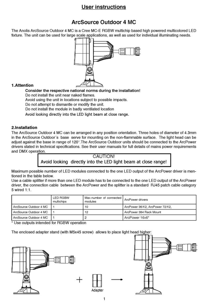
Anolis ArcSource Outdoor 4 MC User manual

Anolis
Anolis ArcPower 16x12 User manual

Anolis
Anolis ArcDot-CE User manual

Anolis
Anolis arcpower smartwhite 72 User manual

Anolis
Anolis ArcWash Recessed 136 RGB User manual

Anolis
Anolis ArcPix User manual

Anolis
Anolis ArcSource Outdoor 24 MC Integral SmartWhite User manual

Anolis
Anolis ArcSource Outdoor 4 MC User manual

Anolis
Anolis arcpad xtreme-ce User manual