manuals.online logo
Brands
  1. Home
  2. •
  3. Brands
  4. •
  5. Anritsu
  6. •
  7. Measuring Instrument
  8. •
  9. Anritsu VectorStar ME7838D4 User manual

Anritsu VectorStar ME7838D4 User manual

Quick Start Guide
VectorStar™ME7838D4
Multiport Broadband/Banded
Millimeter-Wave System
High Performance Modular Broadband/Banded Millimeter-Wave
Vector Network Analyzer (VNA) Multiport Measurement System
ME7838D4, 70 kHz to 145 (150) GHz
Part Number: 10410-00770
Revision: B
Published: December 2019
Copyright 2019 Anritsu Company, USA. All Rights Reserved.
Anritsu Company
490 Jarvis Drive
Morgan Hill, CA 95037-2809
USA
http://www.anritsu.com
1. ME7838D4 Main Components
QSG-2 PN: 10410-00770 Rev. B VectorStar ME7838D4 QSG
High Performance Modular Broadband/Banded Millimeter-Wave
Vector Network Analyzer (VNA) Measurement System, 70 kHz to 150 GHz
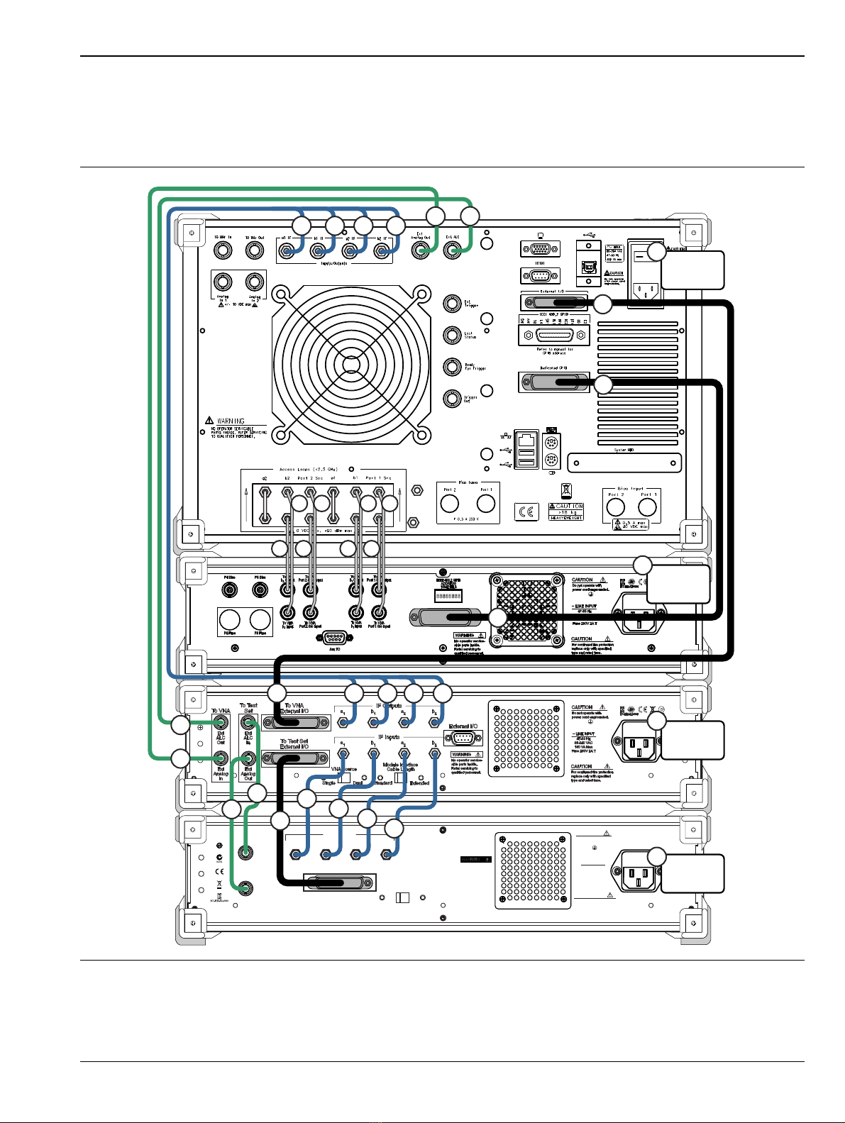
This guide provides quick setup instructions for the ME7838D4 Multiport Broadband/Banded mm-Wave VNA
System assembly. For additional safety and compliance information, and for more details about the assembly,
configuration, setup, and initial testing of the equipment, refer to the VectorStar™ ME7838x4 Series Multiport
Broadband Vector Network Analyzers Installation Guide – 10410-00734.
This and all other documentation that supports the ME7838D4 is available on the VectorStar product web
page:
http://www.anritsu.com/en-us/products-solutions/products/ms4640b-series.aspx
On this web page, you can select various tabs for more information about your instrument. Included is a
“Library” tab which contains links to all the latest technical documentation related to this instrument.
1. ME7838D4 Main Components
ME7838D4 Broadband Systems
The ME7838D4 Multiport Broadband system consists of the following components:
•MS4647A or MS4647B VNA with Option 007 (Receiver Offset) and Option 08x (Modular Broadband
Connection Capability)
•MN4697C Multiport Test Set
•3736B Broadband Test Set
•3739C Broadband Test Set
•Four MA25300A Millimeter-Wave Modules
•Front and rear panel cables
ME7838D4 Banded Systems
The ME7838D4 Multiport Banded system consists of the following components:
•MS464xA/B VNA with Option 08x
•MN4694C Multiport Test Set
•3736B Broadband Test Set
•3739C Broadband Test Set
•Four 3744A-EE, 3744A-EW, or four OML/VDI Millimeter-Wave Modules
•Front and rear panel cables
Caution
A MS464xA/B VNA unit is heavy. To avoid personal injury, it must be lifted and
maneuvered by at least two people during installation.
If mounting on a workbench surface, first position the 3739C Broadband Test Set
with access to its front and rear panels. Stack the remaining test sets on top of one
another, then finally the VNA.
If mounting into rack or console, make sure the Test Sets have been installed, and
that the rack/console is carefully positioned on a flat and level surface. If equipped,
make sure any casters are locked. Use two people to lift the VNA unit and two to
guide it into its shelf rails.
The test loops on the front and rear panels of the VNA are delicate. Be careful not to
bump or bend the test loops.
2. Rear Panel Connections Between System Components (MS464xA VNA)
VectorStar ME7838D4 QSG PN: 10410-00770 Rev. B QSG-3
2. Rear Panel Connections Between System Components
(MS464xA VNA)
In this section, connect the cables between the VNA and the Test Sets as shown in Figure 1 and Table 1.
Figure 1 ME7838D4 – Rear Panel Cable Connections (MS464xA VNA)
WARNING
No operator service-
able parts inside.
Refer servicing to
qualified personnel.
Ext
Alc
Out
Ext
Analog
In
a1ba2b2
IF Outputs
External I/O
~ LINE INPUT
47-63 Hz
85-240 VAC
150 VA Max
Fuse 250V 2A T
CAUTION
Do not operate with
power cord ungrounded.
CAUTION
For continued fire protection
replace only with specified
type and rated fuse.
Cable Length
Standard Extended
Module Interface
MN469xC
Test Set
3736B
Test Set
3739C
Test Set
MS464xA
VNA
1
1
2
2
3
4
11 15
16
17
1812
13
14
19
20
21
22
5
6666
7 7 7 7
7 7 7 7
8
8
9
9
2. Rear Panel Connections Between System Components (MS464xA VNA)
QSG-4 PN: 10410-00770 Rev. B VectorStar ME7838D4 QSG
Table 1. ME7838D4 Multiport Rear Panel Cable Connections (1 of 2)
Index Part Number Cable Description Connection From Connection To
1 3-806-225 BNC (male-male), 24 in MS464xA port labeled:
Ext Analog Out
3736B port labeled:
EXT ANALOG IN
2 3-806-225 BNC (male-male), 24 in MS464xA port labeled:
Ext ALC
3736B port labeled:
EXT ALC OUT
3 3-806-225 BNC (male-male), 24 in
3736B port labeled:
(To Test Set) EXT ANALOG
OUT
3739C port labeled:
EXT ANALOG IN
4 3-806-225 BNC (male-male), 24 in 3736B port labeled:
(To Test Set) EXT ALC IN
3739C port labeled:
EXT ALC OUT
5
73598-1a
(5 cable
bundle)
DB-25 3736B port labeled:
TO TEST SET EXTERNAL I/O
3739C port labeled:
EXTERNAL I/O
6
SMA male-male flexible:
3-72243-1
3-72243-2
3-72243-3
3-72243-4
3736B ports labeled:
(IF INPUTS)
a1
b1
a2
b2
3739C ports labeled:
(IF OUTPUTS)
a1
b1
a2
b2
73-80734a
(5 cable
bundle)
SMA male-male flexible:
3-72243-21
3-72243-22
3-72243-23
3-72243-24
MS464xA ports labeled:
(Inputs/Outputs)
a1 IF
b1 IF
a2 IF
b2 IF
3736B ports labeled:
(IF OUTPUTS)
a1 IF
b1 IF
a2 IF
b2 IF
8DB-25
MS464xA port labeled:
External I/O
3736B port labeled:
TO VNA EXTERNAL I/O
9 2100-1 GPIB, 1 m MS464xA port labeled:
Dedicated GPIB
MN469xC port labeled:
IEEE 488.2 GPIB
11 62112-81aSMA male-male
semi-rigid
MS464xA port labeled:
b2 loop out
MN469xC port labeled:
TO VNA b2 OUTPUT
12 62112-80aSMA male-male
semi-rigid
MS464xA port labeled:
b2 loop in
MN469xC port labeled:
TO VNA b2 INPUT
13 62112-81aSMA male-male
semi-rigid
MS464xA port labeled:
P2 source loop out
MN469xC port labeled:
TO VNA Port 2 Src OUTPUT
14 62112-80aSMA male-male
semi-rigid
MS464xA port labeled:
P2 source loop in
MN469xC port labeled:
TO VNA Port 2 Src INPUT
15 62112-81aSMA male-male
semi-rigid
MS464xA port labeled:
b1 loop out
MN469xC port labeled:
TO VNA b1 OUTPUT
16 62112-80aSMA male-male
semi-rigid
MS464xA port labeled:
b1 loop in
MN469xC port labeled:
TO VNA b1 INPUT
17 62112-81aSMA male-male
semi-rigid
MS464xA port labeled:
P1 source loop out
MN469xC port labeled:
TO VNA Port 1 Src OUTPUT
2. Rear Panel Connections Between System Components (MS464xA VNA)
VectorStar ME7838D4 QSG PN: 10410-00770 Rev. B QSG-5
18 62112-80aSMA male-male
semi-rigid
MS464xA port labeled:
P1 source loop in
MN469xC port labeled:
TO VNA Port 1 Src INPUT
19 MS464xA VNA
20 MN469xC Test Set
21 3736B Test Set
22 3739C Test Set
a. Tighten each cable in this group using an 8 mm (5/16 in) torque end wrench set to 0.9 N·m (8 lbf·in).
Table 1. ME7838D4 Multiport Rear Panel Cable Connections (2 of 2)
Index Part Number Cable Description Connection From Connection To
3. Rear Panel Connections Between Components (MS464xB VNA)
QSG-6 PN: 10410-00770 Rev. B VectorStar ME7838D4 QSG
3. Rear Panel Connections Between Components (MS464xB VNA)
In this section, connect the cables between the VNA and the Test Sets as shown in Figure 2 or Figure 3, and
Table 2.
Cable Connections (Systems with Option 031 Dual Source Architecture)
Figure 2 ME7838D4 Multiport BB/mmW VNA System – Rear Panel Cables (With Option 031)
WARNING
No operator service-
able parts inside.
Refer servicing to
qualified personnel.
Ext
Alc
Out
Ext
Analog
In
a1ba2b2
IF Outputs
External I/O
~ LINE INPUT
47-63 Hz
85-240 VAC
150 VA Max
Fuse 250V 2A T
CAUTION
Do not operate with
power cord ungrounded.
CAUTION
For continued fire protection
replace only with specified
type and rated fuse.
Cable Length
Standard Extended
Module Interface
MN469xC
Test Set
3736B
Test Set
3739C
Test Set
MS464xB
VNA
3
11 15
16
17
18
12
13
14
19
20
21
22
5
6666
7 7 7 7
7 7 7 7
8
8
9
9
Ext In ALC 1
and
Ext In ALC 2
(With Option 031)
Ext ALC 1
(With
Option 031)
1
1
2
2
2
2
4
Ext ALC 2
(With
Option 031)
3. Rear Panel Connections Between Components (MS464xB VNA)
VectorStar ME7838D4 QSG PN: 10410-00770 Rev. B QSG-7
Cable Connections (Systems without Option 031)
Figure 3 ME7838D4 Multiport BB/mmW VNA System – Rear Panel Cables (No Option 031)
WARNING
No operator service-
able parts inside.
Refer servicing to
qualified personnel.
Ext
Alc
Out
Ext
Analog
In
a1ba2b2
IF Outputs
External I/O
~ LINE INPUT
47-63 Hz
85-240 VAC
150 VA Max
Fuse 250V 2A T
CAUTION
Do not operate with
power cord ungrounded.
CAUTION
For continued fire protection
replace only with specified
type and rated fuse.
Cable Length
Standard Extended
Module Interface
MN469xC
Test Set
3736B
Test Set
3739C
Test Set
MS464xB
VNA
3
11 15
16
17
18
12
13
14
19
20
21
22
5
6666
7 7 7 7
7 7 7 7
8
8
9
9
1
1
2
2
4
3. Rear Panel Connections Between Components (MS464xB VNA)
QSG-8 PN: 10410-00770 Rev. B VectorStar ME7838D4 QSG
Table 2. ME7838D4 Multiport Rear Panel Cable Connections (MS464xB) (1 of 2)
Index Part Number Cable Description Connection From Connection To
13-806-225 BNC (male-male), 24 in MS464xB port labeled:
Ext Analog Out
3736B port labeled:
EXT ANALOG IN
2
3-806-225 BNC (male-male), 24 in
VNA port labeled:
Ext In ALC 1
(No Option 031) (Figure 3)
3736B port labeled:
EXT ALC OUT
3-806-225 BNC (male-male), 24 in
VNA port labeled:
Ext In ALC 1
(With Option 031) (Figure 2)
3739C port labeled:
EXT ALC OUT
3-806-225 BNC (male-male), 24 in
VNA port labeled:
Ext In ALC 2
(With Option 031) (Figure 2)
3736B port labeled:
EXT ALC OUT
33-806-225 BNC (male-male), 24 in
3736B port labeled:
(To Test Set) EXT ANALOG
OUT
3739C port labeled:
EXT ANALOG IN
43-806-225 BNC (male-male), 24 in
3736B port labeled:
(To Test Set) EXT ALC IN
(Figure 3)
(Not used with Option 031)
3739C port labeled:
EXT ALC OUT
5
73598-1a
(5 cable
bundle)
DB-25 3736B port labeled:
TO TEST SET EXTERNAL I/O
3739C port labeled:
EXTERNAL I/O
6
SMA male-male flexible:
3-72243-1
3-72243-2
3-72243-3
3-72243-4
3736B ports labeled:
(IF INPUTS)
a1
b1
a2
b2
3739C ports labeled:
(IF OUTPUTS)
a1
b1
a2
b2
73-80734a
(5 cable
bundle)
SMA male-male flexible:
3-72243-21
3-72243-22
3-72243-23
3-72243-24
MS464xB ports labeled:
(Inputs/Outputs)
a1 IF
b1 IF
a2 IF
b2 IF
3736B ports labeled:
(IF OUTPUTS)
a1 IF
b1 IF
a2 IF
b2 IF
8DB-25 MS464xB port labeled:
External I/O
3736B port labeled:
TO VNA EXTERNAL I/O
92100-1 GPIB, 1 m MS464xB port labeled:
Dedicated GPIB
MN469xC port labeled:
IEEE 488.2 GPIB
11 62112-81aSMA male-male
semi-rigid
MS464xB port labeled:
b2 loop out
MN469xC port labeled:
TO VNA b2 OUTPUT
12 62112-80aSMA male-male
semi-rigid
MS464xB port labeled:
b2 loop in
MN469xC port labeled:
TO VNA b2 INPUT
13 62112-81aSMA male-male
semi-rigid
MS464xB port labeled:
P2 source loop out
MN469xC port labeled:
TO VNA Port 2 Src OUTPUT
3. Rear Panel Connections Between Components (MS464xB VNA)
VectorStar ME7838D4 QSG PN: 10410-00770 Rev. B QSG-9
14 62112-80aSMA male-male
semi-rigid
MS464xB port labeled:
P2 source loop in
MN469xC port labeled:
TO VNA Port 2 Src INPUT
15 62112-81aSMA male-male
semi-rigid
MS464xB port labeled:
b1 loop out
MN469xC port labeled:
TO VNA b1 OUTPUT
16 62112-80aSMA male-male
semi-rigid
MS464xB port labeled:
b1 loop in
MN469xC port labeled:
TO VNA b1 INPUT
17 62112-81aSMA male-male
semi-rigid
MS464xB port labeled:
P1 source loop out
MN469xC port labeled:
TO VNA Port 1 Src OUTPUT
18 62112-80aSMA male-male
semi-rigid
MS464xB port labeled:
P1 source loop in
MN469xC port labeled:
TO VNA Port 1 Src INPUT
19 MS464xB VNA
20 MN469xC Test Set
21 3736B Test Set
22 3739C Test Set
a. Tighten each cable in this group using an 8 mm (5/16 in) torque end wrench set to 0.9 N·m (8 lbf·in).
Table 2. ME7838D4 Multiport Rear Panel Cable Connections (MS464xB) (2 of 2)
Index Part Number Cable Description Connection From Connection To
4. Semi-rigid Cable Connections Between System Components
QSG-10 PN: 10410-00770 Rev. B VectorStar ME7838D4 QSG
4. Semi-rigid Cable Connections Between System Components
Make the semi-rigid cable connections as shown in Figure 4 or Figure 5, and in Table 3.
If your system has Option 031 Dual Source Architecture (MS464xB only), use Figure 4. If your system does not
have Option 031, use Figure 5.
Figure 4 ME7838D4 Multiport Semi-rigid Cable Connections (with Option 031 Dual Source Architecture)
+27 dBm MAX AVOID STATIC DISCHARGE
ALL PORTS: CAUTION
Standby Operate
Frequency
Power
Sweep
Avg
Response
Display
Scale
Marker
Channel
Trace
Measurement
Calibration
Application
File
System
Help
Preset
RF LO 2
Out Out
In In
1 1 1 1 1 1 1
7
8
9
10
23
4
5 5
3
1
Install Termination
Removed from
VNA RF1 or RF2
6
4. Semi-rigid Cable Connections Between System Components
VectorStar ME7838D4 QSG PN: 10410-00770 Rev. B QSG-11
Figure 5 ME78383D4 Multiport Semi-rigid Cable Connections (No Option 031)
+27 dBm MAX AVOID STATIC DISCHARGE
ALL PORTS: CAUTION
Standby Operate
Frequency
Power
Sweep
Avg
Response
Display
Scale
Marker
Channel
Trace
Measurement
Calibration
Application
File
System
Help
Preset
RF LO 2
Out Out
In In
1 1 1 1 1 1 1
7
8
9
10
2
3
4
5 5
3
1
4. Semi-rigid Cable Connections Between System Components
QSG-12 PN: 10410-00770 Rev. B VectorStar ME7838D4 QSG
Table 3. ME7838D4 Multiport Semi-rigid Cable Interconnect Part Numbers and Locations (1 of 2)
Index Part Numbers Description/Torque Connection From Connection To
1
3-62109-42
V (m-m)
(MN4697C)
3-67357-38
K (m-m)
(MN4694C)
Front Panel RF Cable (4 each)
V or K male-male semi-rigid
Tighten using an 8 mm (5/16 in)
torque end wrench set to 0.9 N·m
(8 lbf·in).
VNA port labeled:
b1 (In)
MN469xC port labeled:
b1 (In)
VNA port labeled:
b1 (Out)
MN469xC port labeled:
b1 (Out)
VNA port labeled:
Port 1 Source (In)
MN469xC port labeled:
Port 1 Source (In)
VNA port labeled:
Port 1 Source (Out)
MN469xC port labeled:
Port 1 Source (Out)
VNA port labeled:
Port 2 Source (In)
MN469xC port labeled:
Port 2 Source (In)
VNA port labeled:
Port 2 Source (Out)
MN469xC port labeled:
Port 2 Source (Out)
VNA port labeled:
b2 (In)
MN469xC port labeled:
b2 (In)
VNA port labeled:
b2 (Out)
MN469xC port labeled:
b2 (Out)
267357-230
Front Panel RF Cable
K male-male semi-rigid
Tighten using an 8 mm (5/16 in)
torque end wrench set to 0.9 N·m
(8 lbf·in).
VNA port labeled:
RF 2 (Figure 4)
(With Option 031)
3736B Test Set port
labeled:
RF In
VNA port labeled:
RF (Figure 5)
(No Option 031)
3736B Test Set port
labeled:
RF In
367357-231
Front Panel LO Cable (2 each)
K male-male semi-rigid
Tighten using an 8 mm (5/16 in)
torque end wrench set to 0.9 N·m
(8 lbf·in).
VNA port labeled:
LO 1
3736B Test Set port
labeled:
LO 1 In
VNA port labeled:
LO 2
3736B Test Set port
labeled:
LO 2 In
4
67357-232
(With Option
031)
Front Panel RF Cable
K male-male semi-rigid
Tighten using an 8 mm (5/16 in)
torque end wrench set to 0.9 N·m
(8 lbf·in).
VNA port labeled:
RF 1 (Figure 4)
(With Option 031)
3739C Test Set port
labeled:
RF
67357-18
(No Option
031)
3736B Test Set port
labeled:
RF Out (Figure 5)
(No Option 031)
3739C Test Set port
labeled:
RF
5 67357-19
Front Panel LO Cable (2 each)
K male-male semi-rigid
Tighten using an 8 mm (5/16 in)
torque end wrench set to 0.9 N·m
(8 lbf·in).
3736B Test Set port
labeled:
LO 1 Out
3739C Test Set port
labeled:
LO 1
3736B Test Set port
labeled:
LO 2 Out
3739C Test Set port
labeled:
LO 2
6 V210
Termination (With Option 031)
Tighten using an 8 mm (5/16 in)
torque end wrench set to 0.9 N·m
(8 lbf·in).
Remove from VNA port
labeled:
RF 1 or RF 2
(With Option 031)
Add to 3736B Test Set
port labeled:
RF Out
4. Semi-rigid Cable Connections Between System Components
VectorStar ME7838D4 QSG PN: 10410-00770 Rev. B QSG-13
7
MS464xA VNA Option 051, 061, or 062, and 08x (Banded)
MS464xB VNA Option 051, 061, or 062, and 08x (Banded)
MS4647A VNA Option 051, 061, or 062, and 08x (Broadband)
MS4647B VNA Option 051, 061, or 062, and 08x (Broadband)
8
MN4694C
Test Set (Banded)
MN4697C
Test Set (Broadband)
9 3736B Test Set
10 3739C Test Set
Table 3. ME7838D4 Multiport Semi-rigid Cable Interconnect Part Numbers and Locations (2 of 2)
Index Part Numbers Description/Torque Connection From Connection To
5. Front Panel Cable Connections
QSG-14 PN: 10410-00770 Rev. B VectorStar ME7838D4 QSG
5. Front Panel Cable Connections
Make the cable connections as shown in Figure 6 and in Table 4.
Figure 6 Front Panel to mm-Wave Module Connections
+27 dBm MAX AVOID STATIC DISCHARGE
ALL PORTS: CAUTION
RF LO 2
Out Out
In In
Test Port 2
to Module SRC
(MA25300A only)
Test Port 4
to Module SRC
(MA25300A only)
Test Port 1
to Module SRC
(MA25300A only)
Test Port 3
to Module SRC
(MA25300A only)
Port 3
Module
Port 1
Module
Port 2
Module
Port 4
Module
Port 1
Port 4Port 3
Port 2
1
1
6
6
7
7
8
8
9
2
2
3
3
4
4
5
5
10
11
12
5. Front Panel Cable Connections
VectorStar ME7838D4 QSG PN: 10410-00770 Rev. B QSG-15
Note The cables for Test Port 1 through Test Port 4 to Module SRC are not used with mm-Wave modules
3744A-EE, 3744A-EW, or 3744A-Rx.
Table 4. ME7838D4 Cable Interconnect Part Numbers and Locations (1 of 2)
Index Part Number Description Connection From Connection To
1
2
3
4
806-209-Ra,b
Coaxial Cable (4 each)
V male-female flexible, 36 in
Used with MA25300A Broadband Modules
only
Tighten at Test Set using an 8 mm (5/16 in)
torque end wrench set to 0.9 N·m
(8 lbf·in).
MN469xC port
labeled:
Port 1
Port 2
Port 3
Port 4
MA25300A port
labeled:
(Port 1 Module) SRC
(Port 2 Module) SRC
(Port 3 Module) SRC
(Port 4 Module) SRC
5
6
7
8
75685-1a
mm-Wave Module Interface Cables
(for MA25300A, 3743A, 3744A-EE,
3744A-EW modules)
Group of 5 cables for each port
Tighten at Test Set using an 8 mm
(5/16 in) torque end wrench set to 0.9 N·m
(8 lbf·in).
3739C Test Set:
Port 1, Port 2
RF, LO, Test, Ref,
Power/Signal
mm-Wave Modules:
Port 1, Port 2 Modules
RF, LO, Test, Ref,
Power/Signal
3736B Test Set
Port1, Port 2
(Port 3, Port 4)
RF, LO, Test, Ref,
Power/Signal
mm-Wave Modules
Port 3, Port 4 Modules
RF, LO, Test, Ref,
Power/Signal
5
6
7
8
75685-2a
OML Module Interface Cables
Group of 4 cables for each port
Tighten at Test Set using an 8 mm
(5/16 in) torque end wrench set to 0.9 N·m
(8 lbf·in).
3739C Test Set
Port 1, Port 2
RF, LO, Test, Ref
OML Modules
Port 1, Port 2 Modules
RF, LO, Test IF, Ref IF
3736B Test Set
Port1, Port 2
(Port 3, Port 4)
RF, LO, Test, Ref
OML Modules
Port 3, Port 4 Modules
RF, LO, Test IF, Ref IF
VDI Module Interface Cables
Group of 4 cables for each port
Tighten at Test Set using an 8 mm (5/16 in)
torque end wrench set to 0.9 N·m
(8 lbf·in).
3739C Test Set
Port 1, Port 2
RF, LO, Test, Ref
VDI Modules
Port 1, Port 2 Modules
RF Input, LO Input,
Meas. IF, Ref IF
3736B Test Set
Port1, Port 2
(Port 3, Port 4)
RF, LO, Test, Ref
VDI Modules
Port 3, Port 4 Modules
RF Input, LO Input,
Meas. IF, Ref IF
5
6
7
8
75685-3a
mm-Wave Module Interface Cables
(for 3744A-Rx modules) Group of 3
cables for each port
Tighten at Test Set using an 8 mm
(5/16 in) torque end wrench set to 0.9 N·m
(8 lbf·in).
3739C Test Set
Port 1, Port 2
LO, Test,
Power/Signal
Rx Modules
Port 1, Port 2 Modules
LO, Test,
Power/Signal
3736B Test Set
Port1, Port 2
(Port 3, Port 4)
LO, Test,
Power/Signal
Rx Modules
Port 3, Port 4 Modules
LO, Test,
Power/Signal
5. Front Panel Cable Connections
QSG-16 PN: 10410-00770 Rev. B VectorStar ME7838D4 QSG
9
MS464xA VNA – Option 051, 061, or 062, and 08x (Banded)
MS464xB VNA – Option 051, 061, or 062, and 08x (Banded)
MS4647A VNA – Option 051, 061, or 062, and 08x (Broadband)
MS4647B VNA – Option 051, 061, or 062, and 08x (Broadband)
10 MN4694C Test Set (Banded)
MN4697C Test Set (Broadband)
11 3736B Test Set
12 3739C Test Set
a. Do not yet connect the cable ends to the Millimeter-Wave modules. Module connection instructions follow this section.
b. The 806-209-R Coaxial Cable is not included or required when using the 3744A-EE, 3744A-EW mm-Wave modules, or the
3744A-Rx Receiver Module.
Table 4. ME7838D4 Cable Interconnect Part Numbers and Locations (2 of 2)
Index Part Number Description Connection From Connection To
6. Front Panel to Millimeter-Wave Module Connections
VectorStar ME7838D4 QSG PN: 10410-00770 Rev. B QSG-17
6. Front Panel to Millimeter-Wave Module Connections
Connect the 3739C Broadband Test Set Port-1 and Port-2 cables to the MA25300A, 3743A, 3744A-EE,
3744A-EW, or 3744A-Rx Modules as shown below, observing the correct torque limits for each connector. See
Figure 7 and Table 5. Route the cable assemblies through the cable restraint.
Note
For ease of connection, the module can be removed from the bracket, then reinstalled after cables
are secured. Observe torque instructions where indicated.
Each module (except the 3744A-Rx) is characterized for absolute power for a specific VNA Serial
Number and VNA Test Port as designated on the module port assignment label. Ensure the module
matches the correct VNA and Test Set port.
If an alternative MA25300A or 3743 series mm-Wave module is used there will be approximately 1
dB of absolute power inaccuracy, which can be corrected by performing a power calibration.
For more detailed information on the modules including DUT Waveguide (WG) connection alignment
and custom bracket mounting, refer to 10410-00311-VectorStar® Broadband/Banded
Millimeter-Wave Modules Reference Manual.
Figure 7. Millimeter-Wave Module Connections
TEST
LO
Power/Signal
RF
REF
SRC (Not used)
6
5
3744A-EE
3744A-EW
4
9
3
2
3743A
TEST REF
SRC
RF
Power/Signal
1
3
LO 6
5
9
7
8
3743A
4
2
TEST REF
SRC
LO
Power/Signal
RF
(Not used)
(Not used)
(Not used)
5
3743A-Rx
3
6
2
MA25300A
REF 4
2RF
9
SRC
8
LO
6
TEST
3
Power/Signal
5
S/N
11
Port Assignment
10
6. Front Panel to Millimeter-Wave Module Connections
QSG-18 PN: 10410-00770 Rev. B VectorStar ME7838D4 QSG
Inverting a Module
If necessary, a module can be turned over in the bracket to change the height of the DUT connector. To turn
the module over:
1. Remove the six Knurled Head Thumbscrews M2 × 8 mm (four M3 x 8 mm on the MA25300A).
2. Turn the module over
3. Install the cable assembly then install the module into the bracket.
4. Install the thumbscrews.
Table 5. Millimeter-Wave Module Connections
Cable P/N Index Description
N/A 1 Millimeter-Wave Module in bracket
DUT
Connector 2
0.8 mm Connector (MA25300A module)
• Tighten using a torque end wrench and a plain end wrench
• 6 mm Torque End Wrench set to 0.45 N·m (4 lbf·in). Recommended is Anritsu 01-524.
• 6 mm / 7 mm Open End Wrench. Recommended is Anritsu 01-525.
W1 - 1 mm Connector (3743A, 3744A-Rx modules)
• Tighten using a torque end wrench and a plain end wrench
• 6 mm Torque End Wrench set to 0.45 N·m (4 lbf·in). Recommended is Anritsu 01-504.
• 6 mm / 7 mm Open End Wrench. Recommended is Anritsu 01-505.
WR-10 or WR-12 to 1 mm connector (3744A-EE, 3744A-EW modules)
• Use Waveguide Adapter Toolkits (74394-2, 74394-3, or 74394-4).
• Tighten using a torque end wrench and a plain end wrench.
• 6 mm Torque End Wrench set to 0.45 N·m (4 lbf·in). Recommended is Anritsu 01-504.
• 6 mm / 7 mm Open End Wrench. Recommended is Anritsu 01-505.
75685-1a
or
75685-3b,c
3
TEST – SSMC Connector (Connected on all Modules)
• Tighten using a 4 mm (5/32 in) torque end wrench set to less than 0.17 N·m (1.5 lbf·in).
• Recommended is Anritsu 01-529-R torque wrench.
4
REF – SSMC Connector (Connected on all Modules except 3744A-Rx)
• Tighten using a 4 mm (5/32 in) torque end wrench set to less than 0.17 N·m (1.5 lbf·in).
• Recommended is Anritsu 01-529-R torque wrench.
5Power/Signal Latching Bi-Lobe™ Connector (Connected on all modules)
6
LO – K Connector (Connected on all Modules)
• Tighten using an 8 mm (5/16 in) torque end wrench set to 0.9 N·m (8 lbf·in).
• Recommended is Anritsu 01-201.
7 Module Power and I/O Cable Restraint
806-209-Rd8
SRC – V Connector (Connected on MA25300A and 3743A only)
• Tighten using an 8 mm (5/16 in) torque end wrench set to 0.9 N·m (8 lbf·in).
• Recommended is Anritsu 01-201.
75685-1a 9
RF – V Connector (Connected on all Modules except 3744A-Rx)
• Tighten using an 8 mm (5/16 in) torque end wrench set to 0.9 N·m (8 lbf·in).
• Recommended is Anritsu 01-201.
N/A 10 Factory Calibrated Port Assignment Label
N/A 11 Module Serial Number Label
a. Cable assembly 75685-1 is used on MA25300A, 3743A, 3744A-EE, and 3744A-EW modules.
b. The REF cable is not used in the 75685-3 cable assembly.
c. Cable assembly 75685-3 is used on the 3744A-Rx module.
d. The 806-209-R Coaxial Cables are used only with the MA25300A and 3743A modules.
6. Front Panel to Millimeter-Wave Module Connections
VectorStar ME7838D4 QSG PN: 10410-00770 Rev. B QSG-19
Millimeter-Wave Module Operating Environment
The modules require use of heatsink with adequate air circulation. The following notes should be considered
before operating the MA25300A, 3743x, 3744x-xx, and 3743x-Rx Millimeter-Wave Modules:
•Thermal heat sinking similar to the supplied mounting brackets of the Millimeter-Wave Module should
be considered in custom mounting applications.
•Each MA25300A Module consumes a maximum of 12 watts.
•Each 3743x Module consumes a maximum of 12 watts.
•Each 3744x-EE and 3744x-EW Module consumes a maximum of 12 watts.
•Each 3744x-Rx Module consumes a maximum of 7 watts.
•The primary heat sinking path for the module is on the two external side surfaces used to mount to the
support brackets.
•With the attached cable mounting brackets, the case temperature rise is approximately 15 °C to 20 °C
above ambient.
7. Front Panel to OML/VDI Module Connections
QSG-20 PN: 10410-00770 Rev. B VectorStar ME7838D4 QSG
7. Front Panel to OML/VDI Module Connections
Connect the front panel cables between the 3736B and 3739C Test Sets, and the OML or VDI frequency
extension modules as shown in Figure 8, Figure 9, and Figure 10, and as described in Table 6, Table 7, and
Table 8.
Caution To avoid connector damage, observe torque requirements where indicated.
Figure 8 Cable Connections between 3736B, 3739C Test Sets, and OML or VDI Frequency Extension Modules
+27 dBm MAX AVOID STATIC DISCHARGE
ALL PORTS: CAUTION
RF LO 2
Out Out
In In
Port 3
Module
Port 1
Module
Port 2
Module
Port 4
Module
Port 1
Port 4Port 3
Port 2
Port 2 RF, LO, Test, Ref
to OML/VDI Module
Port 1 RF, LO, Test, Ref
to OML/VDI Module
Port 3 RF, LO, Test, Ref
to OML/VDI Module
Port 4 RF, LO, Test, Ref
to OML/VDI Module
12
3 4
5
6
7

Other Anritsu Measuring Instrument manuals

Anritsu VNA Master MS202 B Series User manual

Anritsu

Anritsu VNA Master MS202 B Series User manual

Anritsu ML2400A Series User manual

Anritsu

Anritsu ML2400A Series User manual

Anritsu MT8820C Installation and operating instructions

Anritsu

Anritsu MT8820C Installation and operating instructions

Anritsu MD1230B User manual

Anritsu

Anritsu MD1230B User manual

Anritsu MP1777A User manual

Anritsu

Anritsu MP1777A User manual

Anritsu MS2840A User manual

Anritsu

Anritsu MS2840A User manual

Anritsu VectorStar ME7848A Series User manual

Anritsu

Anritsu VectorStar ME7848A Series User manual

Anritsu Site Master S810D User manual

Anritsu

Anritsu Site Master S810D User manual

Anritsu Network Master MU909020A User manual

Anritsu

Anritsu Network Master MU909020A User manual

Anritsu Power Master MA24507A User manual

Anritsu

Anritsu Power Master MA24507A User manual

Anritsu LMR Master User manual

Anritsu

Anritsu LMR Master User manual

Anritsu MP1570A User manual

Anritsu

Anritsu MP1570A User manual

Anritsu MT1000A Network Master Pro User manual

Anritsu

Anritsu MT1000A Network Master Pro User manual

Anritsu MP1763C User manual

Anritsu

Anritsu MP1763C User manual

Anritsu Spectrum Master MS2723B User manual

Anritsu

Anritsu Spectrum Master MS2723B User manual

Anritsu VectorStar ME7838 Series User manual

Anritsu

Anritsu VectorStar ME7838 Series User manual

Anritsu MP1800A User manual

Anritsu

Anritsu MP1800A User manual

Anritsu Spectrum Master MS2721B User manual

Anritsu

Anritsu Spectrum Master MS2721B User manual

Anritsu MS2690A User manual

Anritsu

Anritsu MS2690A User manual

Anritsu VectorStar MS4640A Series User manual

Anritsu

Anritsu VectorStar MS4640A Series User manual

Anritsu Sire Master S331D User manual

Anritsu

Anritsu Sire Master S331D User manual

Anritsu K250 User manual

Anritsu

Anritsu K250 User manual

Anritsu IQ Fiber Master MT2780A User manual

Anritsu

Anritsu IQ Fiber Master MT2780A User manual

Anritsu VNA Master MS2024B User manual

Anritsu

Anritsu VNA Master MS2024B User manual

Popular Measuring Instrument manuals by other brands

Sentry Saf-T-Vise STV-HP2 Installation, operation & maintenance manual

Sentry

Sentry Saf-T-Vise STV-HP2 Installation, operation & maintenance manual

AWT PIM-P user manual

AWT

AWT PIM-P user manual

Selec EM306A user manual

Selec

Selec EM306A user manual

Schilling Megalight manual

Schilling

Schilling Megalight manual

Zennio KES Plus user manual

Zennio

Zennio KES Plus user manual

Autonics KRN50 SERIES user manual

Autonics

Autonics KRN50 SERIES user manual

REED MS2301 instruction manual

REED

REED MS2301 instruction manual

Sea-Bird Scientific ECO-FLNTUS product manual

Sea-Bird Scientific

Sea-Bird Scientific ECO-FLNTUS product manual

Panasonic LP-400 Series External Control Manual

Panasonic

Panasonic LP-400 Series External Control Manual

BRONKHORST mini CORI-FLOW Quick installation guide

BRONKHORST

BRONKHORST mini CORI-FLOW Quick installation guide

Arthur Grillo DA2000 Series Installation and operation manual

Arthur Grillo

Arthur Grillo DA2000 Series Installation and operation manual

RS PRO 623-883 Instruction leaflet

RS PRO

RS PRO 623-883 Instruction leaflet

MICRO-EPSILON optoControl 1200 operating instructions

MICRO-EPSILON

MICRO-EPSILON optoControl 1200 operating instructions

Hilti PR 300-HV2S operating instructions

Hilti

Hilti PR 300-HV2S operating instructions

LeCroy Advisor user manual

LeCroy

LeCroy Advisor user manual

Victron energy EM24 manual

Victron energy

Victron energy EM24 manual

IWS TC-412 User and installation guide

IWS

IWS TC-412 User and installation guide

Sonel CMP-3kR user manual

Sonel

Sonel CMP-3kR user manual

manuals.online logo
manuals.online logoBrands
  • About & Mission
  • Contact us
  • Privacy Policy
  • Terms and Conditions

Copyright 2025 Manuals.Online. All Rights Reserved.