logo
Brands
  1. Home
  2. •
  3. Brands
  4. •
  5. ANTAIRA
  6. •
  7. Switch
  8. •
  9. ANTAIRA LNP-0800G-M12-67-24 User manual

ANTAIRA LNP-0800G-M12-67-24 User manual

Other manuals for LNP-0800G-M12-67-24

1

Other ANTAIRA Switch manuals

ANTAIRA LMP-C602G-SFP-bt-V2 Series User manual

ANTAIRA

ANTAIRA LMP-C602G-SFP-bt-V2 Series User manual

ANTAIRA LMX-C602G-SFP-V2 Series User manual

ANTAIRA

ANTAIRA LMX-C602G-SFP-V2 Series User manual

ANTAIRA LNP-C501G-SFP-bt Series User manual

ANTAIRA

ANTAIRA LNP-C501G-SFP-bt Series User manual

ANTAIRA LNX-1802G-SFP Series User manual

ANTAIRA

ANTAIRA LNX-1802G-SFP Series User manual

ANTAIRA LNX-C500-T-CC User manual

ANTAIRA

ANTAIRA LNX-C500-T-CC User manual

ANTAIRA LNP-0702G-SFP-24 Series User manual

ANTAIRA

ANTAIRA LNP-0702G-SFP-24 Series User manual

ANTAIRA LNX-1802GN User manual

ANTAIRA

ANTAIRA LNX-1802GN User manual

ANTAIRA LMP-1204G-SFP-bt Series User manual

ANTAIRA

ANTAIRA LMP-1204G-SFP-bt Series User manual

ANTAIRA LNP-1002G-SFP-24 Series User manual

ANTAIRA

ANTAIRA LNP-1002G-SFP-24 Series User manual

ANTAIRA LMP-0800G Series User manual

ANTAIRA

ANTAIRA LMP-0800G Series User manual

ANTAIRA LMX-0500-V2 Series User manual

ANTAIRA

ANTAIRA LMX-0500-V2 Series User manual

ANTAIRA LMX-0600 Series User manual

ANTAIRA

ANTAIRA LMX-0600 Series User manual

ANTAIRA LNX-1204G-10G-SFP User manual

ANTAIRA

ANTAIRA LNX-1204G-10G-SFP User manual

ANTAIRA LNP-1002G-10G-SFP-24 User manual

ANTAIRA

ANTAIRA LNP-1002G-10G-SFP-24 User manual

ANTAIRA LNX-C800 Series User manual

ANTAIRA

ANTAIRA LNX-C800 Series User manual

ANTAIRA LNP-0500-24 Series User manual

ANTAIRA

ANTAIRA LNP-0500-24 Series User manual

ANTAIRA LMP-1802G-M12-10G-SFP-67-110 Series User manual

ANTAIRA

ANTAIRA LMP-1802G-M12-10G-SFP-67-110 Series User manual

ANTAIRA LNX-C800 Series User manual

ANTAIRA

ANTAIRA LNX-C800 Series User manual

ANTAIRA LMX-2004G-SFP Series User manual

ANTAIRA

ANTAIRA LMX-2004G-SFP Series User manual

ANTAIRA LNX-1600-E Series User manual

ANTAIRA

ANTAIRA LNX-1600-E Series User manual

ANTAIRA LMP-1202M-SFP-24 Series User manual

ANTAIRA

ANTAIRA LMP-1202M-SFP-24 Series User manual

ANTAIRA LNX-500AG User manual

ANTAIRA

ANTAIRA LNX-500AG User manual

ANTAIRA LNP-0800 Series User manual

ANTAIRA

ANTAIRA LNP-0800 Series User manual

ANTAIRA LMP-1202M-SFP Series User manual

ANTAIRA

ANTAIRA LMP-1202M-SFP Series User manual

Popular Switch manuals by other brands

TRENDnet TK-401R null

TRENDnet

TRENDnet TK-401R null

TRENDnet TK-200K null

TRENDnet

TRENDnet TK-200K null

TRENDnet TE100-S8 null

TRENDnet

TRENDnet TE100-S8 null

URC Total Control MFS-8 installation manual

URC

URC Total Control MFS-8 installation manual

Azbil HPQ-D11 user manual

Azbil

Azbil HPQ-D11 user manual

Sony DFS-900M operating instructions

Sony

Sony DFS-900M operating instructions

SICK i17S operating instructions

SICK

SICK i17S operating instructions

F&F SZR-277 quick start guide

F&F

F&F SZR-277 quick start guide

Shure UAMS/BK user guide

Shure

Shure UAMS/BK user guide

Dräger X-zone Switch Off Instructions for use

Dräger

Dräger X-zone Switch Off Instructions for use

Asco Joucomatic 349 Series manual

Asco

Asco Joucomatic 349 Series manual

BT Mini Hub user guide

BT

BT Mini Hub user guide

D-Link DES-1226G manual

D-Link

D-Link DES-1226G manual

Johnson Controls FS80-C installation instructions

Johnson Controls

Johnson Controls FS80-C installation instructions

MicroNet SP1200A user manual

MicroNet

MicroNet SP1200A user manual

Ruijie RG-PF2920 Series Hardware  installation and reference guide

Ruijie

Ruijie RG-PF2920 Series Hardware installation and reference guide

Altinex DA1914SX user guide

Altinex

Altinex DA1914SX user guide

RJM MASTERMIND PBC/6X user manual

RJM

RJM MASTERMIND PBC/6X user manual

https://manuals.online logo
https://manuals.online logoBrands
  • About & Mission
  • Contact us
  • Privacy Policy
  • Terms and Conditions

Copyright 2026 Manuals.Online. All Rights Reserved.

Antaira Technologies
LNP-0800G-M12-67-24
8-Port M12 Industrial IP67 Waterproof Gigabit PoE+ Ethernet
Switch, with 8*10/100/1000Tx with M12 Connector
Quick Installation Guide
Version 1.0
(June 2018)
Tel: 1-844-268-2472
Fax: 1-714-671-9944
www.antaira.com
19020000000067
Package Check List
The package contains the following items:
⚫1 –Quick installation guide
⚫1 –LNP-0800G-M12-67-24
⚫10 –M12 protective caps
Front Panel Layout
1. Power 1 LED
2. Power 2 LED
3. Fault LED
4. PoE Load LED
5. 10/100/1000Mbps Link/Act LED
6. PoE Output LED
7. Screw Holes for Wall Mounting
8. Grounding Screw
9. Power Input Port: M12 4-Pin T-Coded Male Connector
10. Product Label
11. 10/100/1000Base-T(X) Ethernet Port: From port G1 to G8
with M12 8-Pin X-Coded Female Connector
Product Overview
System Interface/Performance
All Ethernet ports support the auto MDI/MDI-X function
M12 connector with IP67 rated protection
Store-and-forward switching architecture
Power Input & Connection
DC 24 to 55V redundant power
It is recommended to use a UL listed industrial power supply
Operating Temperature
operating temperature: -10°C to 60°C
Case/Installation
IP67 protection
Wall Mount design
LED Indicators
LED
Color
Description
P1
Green
On
Power input 1 is active
Off
Power input 1 is inactive
P2
Green
On
Power input 2 is active
Off
Power input 2 is inactive
FAULT
Red
On
There were three possible conditions
would make LED light up:
1. If the current PoE output of all
connected PDs was overload
(>200 Watts)
2. If Power input 1 or Power 2 was
inactive
3. If the current PoE output of one or
more PDs were overload
(>30Watts)
Off
Since the last reset of the FAULT
LED, the PoE output of all connected
PDs has not over 200W and no PD
has been overloaded in this period
and the power 1 & power 2 have not
failed
PoE LOAD
Off
Off
The current PoE output of all
connected PDs is ≤ 50%
Green
On
The current PoE output of all
connected PDs is 51% ~ 70%
Blue
On
The current PoE output of all
connected PDs is 71% ~ 90%
Red
On
The current PoE output of all
connected PDs is 91% ~ 100%
Note: The Max. PoE output of this switch is 200Watts.
L/A
(G1 to G8)
Green
On
Connected to network with 1000
Mbps
Flashing
Networking is active
Off
Not connected to network
Amber
On
Connected to network with 10/100
Mbps
Flashing
Networking is active
Off
Not connected to network
PoE.
(G1 to G8)
Orange
On
The current PoE output is enabled
Flashing
Overload occurred (>30Watts) at the
connected PD
Off
The current PoE output is disabled
Quick Installation
Ethernet Ports
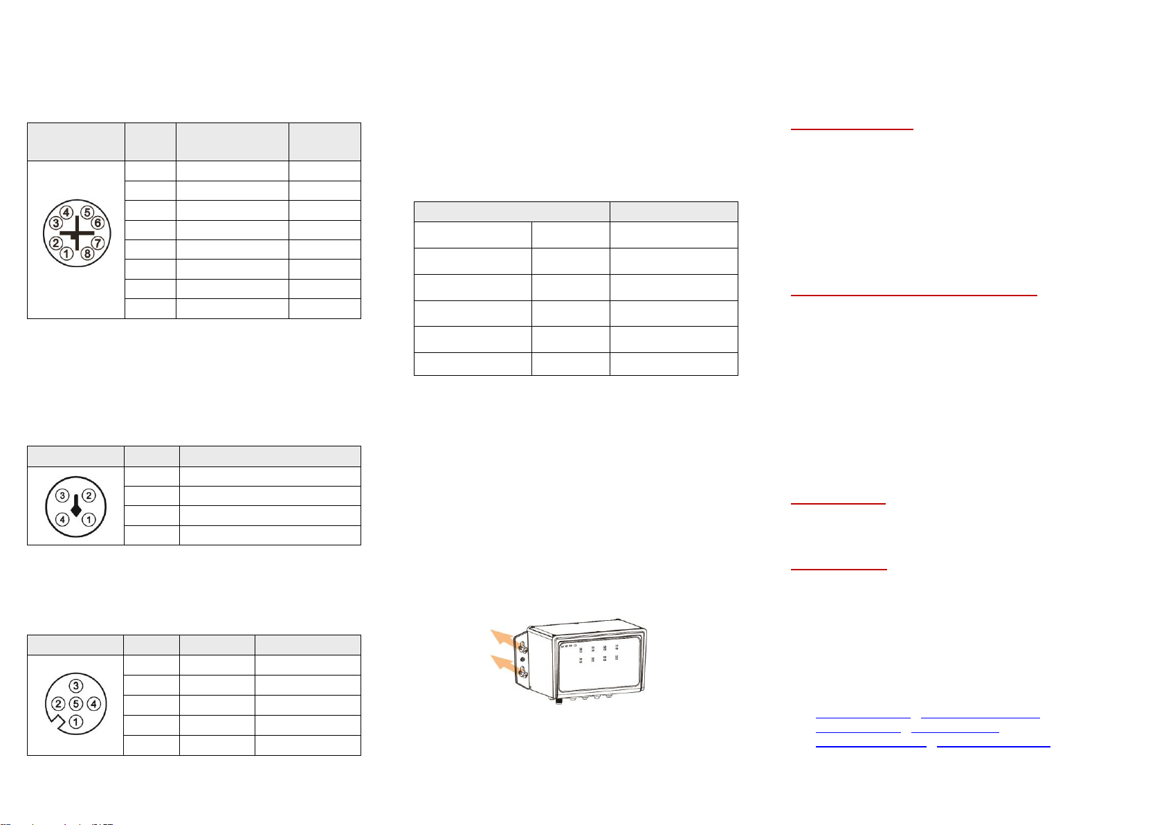
M12 Ports (Auto MDI/MDI-X)
All M12 ports (8-Pin X-Coded Female Connector) are
auto-sensing for 10Base-T, 100Base-TX, or 1000Base-T device
connections. Please follow the wiring pin assignment table below
for Ethernet port installation.
Illustration
Pinout
s
10/100Base-T(X)
Signal
1000Base-
T
Signal
1
Transmit Data +
(TX+)
BI_DA+
2
Transmit Data -
(TX-)
BI_DA-
3
Receive Data +
(RX+)
BI_DB+
4
Receive Data -
(RX-)
BI_DB-
5
BI_DD+
6
BI_DD-
7
BI_DC-
8
BI_DC+
NOTE: Recommended use the wire gauge between 18AWG.
Power Input Wiring
•Input voltage: 24-55VDC
•Dual DC power inputs for power redundancy
•Connection format: M12 4-Pin T-Coded male connector
•Suggest using UL listed industrial power supply
•Pin assignment of M12 power connector:
Illustration
Pinouts
Function
1
Power Input 1 + (V1+)
2
Power Input 1 - (V1-)
3
Power Input 2 - (V2-)
4
Power Input 2 + (V2+)
NOTE: Recommended use the wire gauge between 24AWG.
Relay Contact and Digital Input
•Connection format: M12 5-Pin A-Coded Female Connector
•Minimum Wire Gauge: 24AWG
Illustration
Pinouts
Function
Function
1
DI+
Digital Input +
2
Relay Com
Relay Common
3
Relay (N.C.)
Normally Closed
4
DI-
Digital Input -
5
NA
Not Assigned
By using a M12 5-Pin A-Coded cable to connect the normally
closed relay contact, it will detect the fault status and form an
open circuit when any of the following abnormal conditions
occurs:
1. If the current PoE output of all connected PDs was overload
(>200 Watts)
2. If the current PoE output of one or more PDs were overload
(>30Watts)
3. If Power input 1 or Power 2 was inactive
•Digital Input (DI)
The digital input is used for monitoring two external events via
an external voltage source. When the voltage level on digital
input pins changes from high voltage to low voltage, the DI
function will be triggered. Below table is shown a detail
specification of the digital input.
Specification
Description
Level 0 (Low)
-30~8VDC
Will trigger DI function
(active trigger states)
Level 1 (High)
10~30VDC
Normal Status
(inactive trigger states)
Nominal input
voltage
24VDC
Max. input voltage
30VDC
Nominal input
current
5mA
(typical)
Max. input current
8mA
If the fault status happens, you have to use DI function to reset
the Fault LED, so there are two DI functions this unit supports for
manually reset or reboot the device:
1. When the trigger time < 4 seconds, the relay contact will
be reset and the Fault LED light down.
2. When the trigger time > 4 seconds, the Ethernet switch
will be rebooted.
Bypass Function
This Ethernet switch supports bypass function by two Ethernet
ports (G7 and G8). When one of the Ethernet switches loses
power, Ethernet ports (G7 and G8) will bypass the power lost
Ethernet switch to prevent the network from disconnecting.
Wall Mounting Installation
Follow the steps below to mount the switch to a wall using the
screw holes.
Step 1.
Prepare 4 screws for mounting the switch to a
wall. (Recommended use the M6 screws.)
Step 2.
Based on the positions of 4 screw holes on the left
and right side of the switch to make 4 screw holes
on a wall accordingly.
Step 3.
Insert the screws through the screw holes on the
switch and screw the switch into the wall.
Step 4.
To remove the switch from the wall, do the
opposite from the steps above.
Warranty Policy
Warranty Conditions
Products supplied by Antaira Technologies are covered in this
warranty for sub-standard performance or defective
workmanship. The warranty is not, however, extended to goods
damaged in the following circumstances:
(a) Excessive forces or impacts
(b) War or an Act of God: wind storm, fire, flood, electric shock,
earthquake
(c) Use of unqualified power supply, connectors, or
unauthorized parts/kits
(d) Replacement with unauthorized parts
RMA and Shipping Costs Reimbursement
Customers shall always obtain an authorized "RMA" number
from Antaira before shipping the goods for repair or
replacement.
•Within the warranty period (based on the invoice date), all
parts and labor are free of charge to the customers.
•Customers are responsible for the cost of parts and labor, if
the products are out of warranty.
•For RMA service, customers are responsible for the shipping
expense for shipping the RMA unit(s) to Antaira. Antaira is
responsible for the shipping expense via a ground service
for the return repair/replace unit(s) back to customers.
Limited Liability
Antaira would not be held responsible for any consequential
losses from using Antaira’s product.
Warranty Period
5-Year Warranty
Antaira’s Customer Service and Support
•Antaira’s Technical Service & Support Centers:
+ 844-268-2472 (Antaira US Headquarter)
+ 48-22-862-88-81 (Antaira Europe Office)
+ 886-2-2218-9733 (Antaira Asia Office)
•Antaira’s Web Sites & Repair/Support Emails:
www.antaira.com / [email protected]
www.antaira.eu / i[email protected]
www.antaira.com.tw / i[email protected]
*Any changes will be announced on the Antaira website.