4. Passage of air bubbles through the flow cell will lead to unacceptable noise levels and
‘spikes’. Therefore, the use of an in-line degasser is strongly recommended. In our
experience, a one-time degassing step of the HPLC buffer is almost never sufficient.
Follow the procedure below to install the SenCell, see figure 3 and 4 on the next page for reference:
1. If applicable, install the SenCell clamp (p/n 250.0102A) from the shipkit (p/n 116.0202) in the
center position of the DECADE II detector with a Phillips screwdriver. For other types of Antec
detectors please consult the corresponding detector user manual.
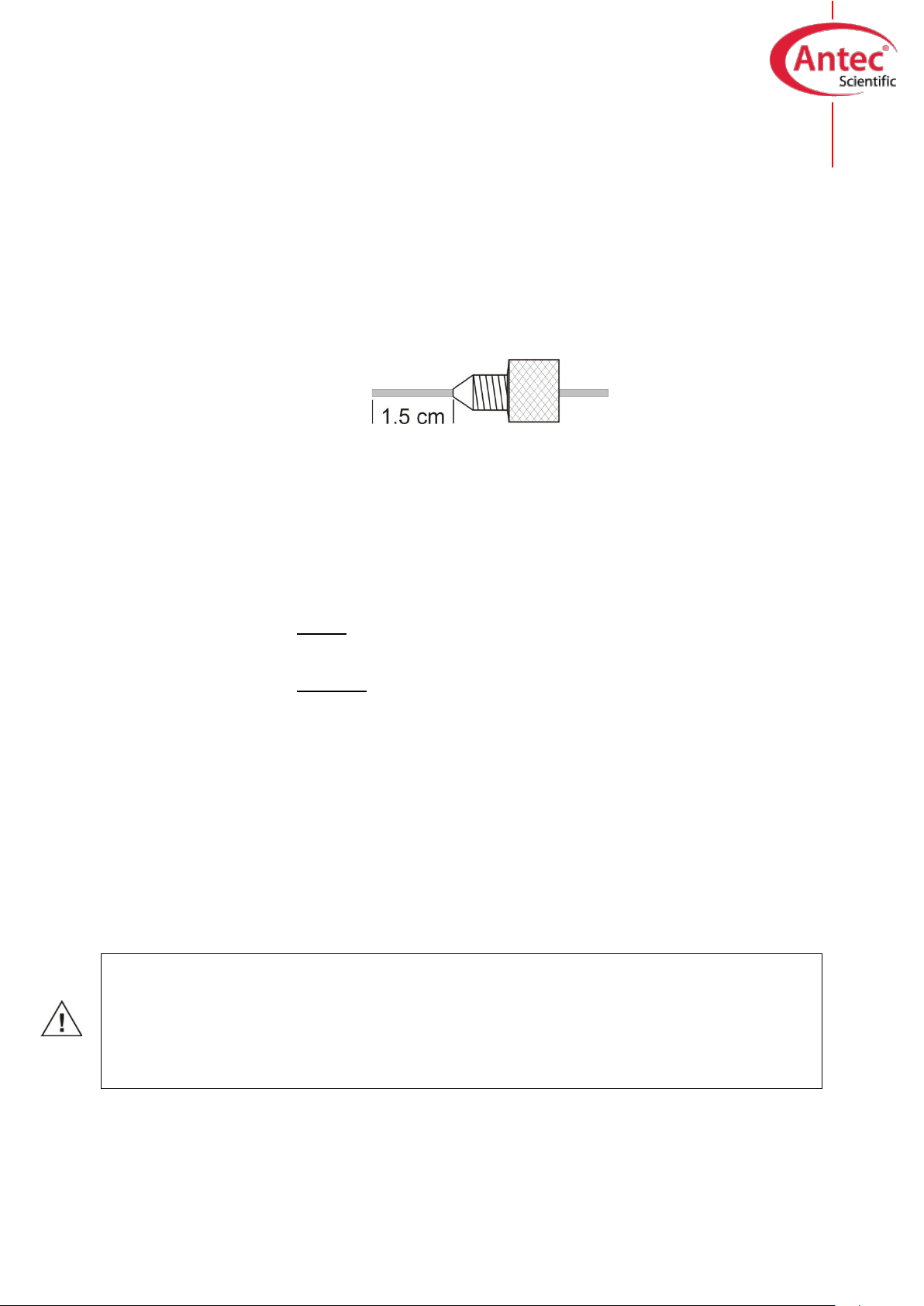
2. Connect the column to the flow cell inlet using 1/16” OD small-bore PEEK tubing (0.3 mm ID
or smaller depending on the column bore size) using the PCTFE 10-32 fingertight (p/n
250.1571). Use only our factory supplied fingertights in the flow cell, others may cause
serious damage!
Let the tubing protrude for ca. 1.5 cm from the fingertight fitting and tighten it such that the
tubing is not or slightly indented by the fitting. Do not over-tighten the fingertight. Over-
tightening affects the flow pattern through the tubing (turbulence) and may strongly decrease
the flow cell performance.
3. Connect 0.5 mm ID PEEK tubing to the outlet of the flow cell. Use only our factory supplied
fingertights in the flow cell, others may cause serious damage! Again (see above), do not
over-tighten the fingertight.
4. Turn on the HPLC pump. Keep some tissues at hand as you probably will spill some mobile
phase during this mounting procedure.
5. For a SenCell with HyREF (black inlet block) or ISAAC reference (green inlet block): fill the
flow cell, by keeping it in an angle of about 45° with the outlet (LC out) on top to force the air
through the outlet.
For a SenCell with Saltbridge reference (blue inlet block): fill the flow cell, by keeping it in an
angle of 45° with the REF fitting on top, is best done by blocking the outlet with a finger and
letting the air escape via the REF fitting. Carefully check the thread of the fitting for trapped air
bubbles. When the REF fitting is completely filled with mobile phase, mount the REF while
slowly releasing the outlet. Make sure not to include an air bubble!
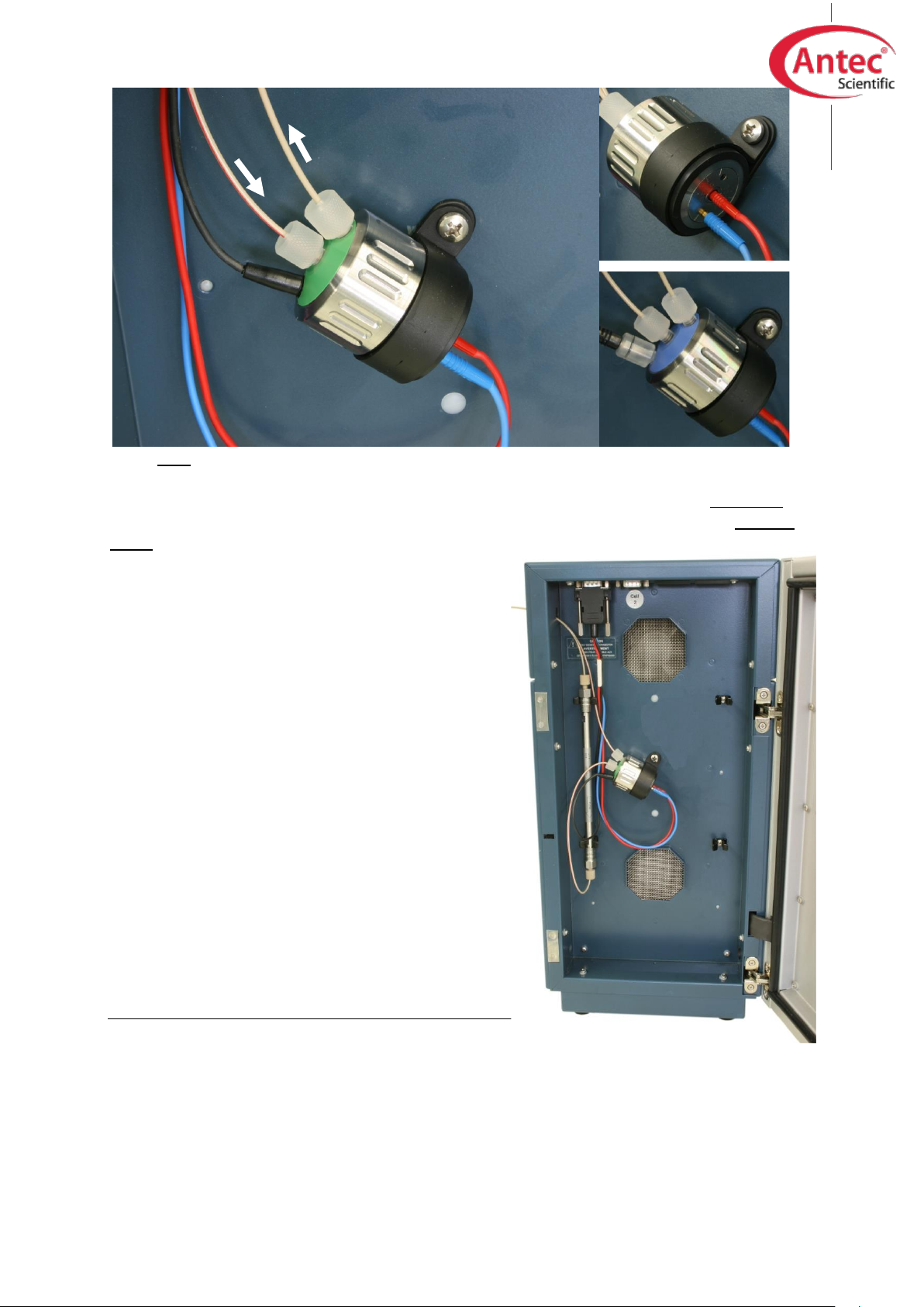
6. Position the flow cell in its clamp in the controller with the REF at the lower side and the outlet
at the upper side. This excludes trapping of air bubbles.
7. Connect the cell cable as shown in the figure on the next page. Red: WE contact, blue: AUX
contact and black: REF contact.
8. Switch ON the SenCell and let the cell backcurrent stabilize before starting your (U)HPLC-
ECD analysis.
Your SenCell is now ready for use.
Never switch ON the flow cell when:
- the cell cable is not correctly connected
- the cell is only partly (or not at all) filled with buffer/electrolyte
- the outside of the flow cell is wet, particularly the part between the auxiliary and working
electrode connection
because substantial damage to the working electrode or electronics may occur.