manuals.online logo
Brands
  1. Home
  2. •
  3. Brands
  4. •
  5. Antec
  6. •
  7. Desktop
  8. •
  9. Antec ISK 310-150 User manual

Antec ISK 310-150 User manual

ISK 310-150
U
SER
’
S
M
ANUAL
1
T
ABLE OF
C
ONTENTS
I
NTRODUCTION
1.1 Case Specificati ns.…..………………………………………………………………………………….. 3
1.2 Diagram…………………………………………………………………….…………………………………. 3
1.3 P wer Supply Specificati ns…………………………………………………………………………. 4
H
ARDWARE
I
NSTALLATION
G
UIDE
2.1 Rem ving the T p Panel.……………………………………………………………………………….5
2.2 Rem ving the Drive Tray Assembly……….……………………………………………………… 5
2.3 M therb ard Installati n..……………………………………………………………………………. 5
2.4 Internal 2.5” Device Installati n……………………………………………………………………. 5
2.5 External Slim 5.25” Device Installati n…………………………………………………………. 6
C
ONNECTING THE
F
RONT
I/O
P
ORTS
3.1 USB 2.0 P rts………………………………………………….……………………………………………. 7
3.2 eSATA P rt…………………………………….……………………………………………………………… 7
3.3 AC’97 / HD Audi P rts……………………….………………………………………………………… 7
3.4 Switch and LED C nnect rs…………………………………………………………………………… 8
3.5 Rewiring M therb ard Header C nnecti ns………………………………………………… 8
C
OOLING
S
YSTEM
4.1 TriC l™ Exhaust Fan……………………………………………………………………………………. 9
2
ISK
310-150
U
SER
’
S
M
ANUAL
At Antec, we c ntinually refine and impr ve ur pr ducts t ensure the highest quality. It’s p ssible
that y ur new case will differ slightly fr m the descripti ns in this manual. This isn’t a pr blem; it’s
simply an impr vement. As f the date f publicati n, all features, descripti ns, and illustrati ns in
this manual are c rrect.
Disclaimer
This manual is intended nly as a guide f r Antec’s c mputer encl sures. F r m re c mprehensive
instructi ns n installing the m therb ard and peripherals, please refer t the user’s manuals that
c me with th se c mp nents.
Alth ugh care has been taken t prevent sharp edges in y ur Antec case, we str ngly rec mmend
taking the appr priate time and care when w rking with it. Av id hurried r careless m ti ns. Please
use reas nable precauti n.
This manual is n t designed t c ver CPU, RAM, r expansi n card installati n. Please c nsult the
m therb ard manual f r specific m unting instructi ns and tr ublesh ting. Bef re pr ceeding,
check the manual f r y ur CPU c ler t find ut if there are steps y u must take bef re installing the
m therb ard. While installing hardware, keep y ur case n a flat, stable surface.
3
1.1 C
ASE
S
PECIFICATIONS
Case Type
Mini-ITX Deskt p
C l r
Silver
Dimensi ns
96mm (H) X 222mm (W) X 328mm (D)
3.8” (H) x 8.7” (W) x 12.9” (D)
Net Weight
5.5 lb / 2.5 kg
C ling
1 x side 80mm TriC l™ fan
Drive Bays
3 drive bays:
-1 x External 5.25” slim drive bay
-2 x Internal 2.5” drive bays
Expansi n Sl ts 1 x half-height sl t
M therb ard Size
Mini-ITX
Fr nt I/O Panel
2 x USB 2.0
1 x eSATA
AC’97 / HD Audi In and Out
P wer
Supply
F
P
-
150
-
8
p wer supply
1.
D
IAGRAM
1. Side 80mm TriC l™ fan
2. External slim ptical 5.25” drive bay
3. Internal 2 x 2.5” HDD bays
4. Half-height expansi n sl t
5. M therb ard m unt – Mini-ITX
6. Fr nt I/O panel
7. FP-150 p wer supply
Note: The ISK 310-150-8 includes a t l bag with Pr duct Overview l cated inside f the case.
4
1.3 P
OWER
S
UPPLY
S
PECIFICATIONS
The ISK 310-150 is p wered by an FP-150-8 p wer supply.
Input characteristics:
Input Voltage Range
Frequency Range
100 VAC ~ 240 VAC 47 Hz ~ 63 Hz
Output characteristics:
DC Output +5V +3.3V +12V -12V +5Vsb
Max. Output 10A 8A 10A 0.2A 1.5A
+3.3V and +5V maximum c mbined utput: 65W
T tal C ntinu us P wer: 150W
A variety f industrial-grade safety circuitry will help pr tect y ur c mputer: OVP (Over V ltage
Pr tecti n), SCP (Sh rt Circuit Pr tecti n), and OCP (Over Current Pr tecti n). S metimes the
PSU will “latch” int a pr tected shutd wn state. This means that y u will need t p wer ff the
supply and clear the fault bef re it will functi n again.
There are n user-replaceable fuses in the FP-150-8.
5
H
ARDWARE
I
NSTALLATION
G
UIDE
.1
R
EMOVING THE TOP PANEL
Place the case flat n an even, stable surface.
1. Rem ve the three thumbscrews fr m the rear f the
t p panel.
2. Grip the t p panel and slide it back several inches
until it st ps.
3. Grip the panel fr m the sides and lift it up until it
pulls c mpletely free f the main chassis.
Note: D n t use y ur fingernails t pry r lift the
panels.
. R
EMOVING THE DRIVE TRAY ASSEMBLY
Rem ve the t p panel as detailed in secti n 2.1.
1. Using a Phillips-head screwdriver, rem ve the three screws n the
t p f the tray that attach it t the chassis.
2. Grip the tray in the middle and pull it a few inches t ward the rear
f the case until it pulls l se.
3. Pull the drive tray assembly up and c mpletely free f the chassis.
.3
M
OTHERBOARD
I
NSTALLATION
Rem ve the t p panel and rem ve the drive tray assembly as detailed in secti ns 2.1 and 2.2.
1. Lay the case d wn, with the pen side facing up. The drive cages and
p wer supply sh uld be visible.
2. Make sure y u have the c rrect I/O panel f r y ur m therb ard. If
the panel pr vided with the case isn’t suitable, please c ntact y ur
m therb ard manufacturer f r the c rrect I/O panel. Install the I/O
panel at the rear f the case.
3. Align y ur m therb ard with the m therb ard stand ff h les
l cated at the rear f the case.
4. Screw in y ur m therb ard t the stand ffs with the pr vided
Phillips-head screws.
Y ur m therb ard is n w installed.
6
.4
I
NTERNAL
.5”
D
EVICE
I
NSTALLATION
Rem ve the t p panel as described in secti n 2.1. Included at the t p
f the drive tray assembly is a HDD tray that can supp rt up t tw
2.5” devices.
1. On the right side f the drive tray assembly, rem ve the
thumbscrew h lding the HDD tray t the rest f the device.
2. Slide the HDD tray back a centimeter s the l cking hinges
unh k.
3. Pull the HDD tray away fr m the drive tray assembly.
4. Align y ur 2.5” device with the HDD tray. Invert the tray s the
l wer screw h les are accessible, and then secure the device t
the tray with the pr vided Phillips-head screws.
5. Reattach the HDD tray t the drive tray assembly and replace
the thumbscrew.
6. C nnect the data and p wer c nnect rs fr m the m therb ard
and p wer supply t the device.
.5
E
XTERNAL
S
LIM
O
PTICAL
D
EVICE
I
NSTALLATION
Rem ve the t p panel and drive tray assembly as described in secti ns 2.1 and 2.2. There is ne
externally accessible slim ptical drive bay that is c mpatible with a slim ptical drive.
1. While facing the fr nt f the case, press n the upper right f
the fr nt f the drive bay c ver until it clicks, then release t
all w the c ver t unhinge.
2. Rem ve the drive bay face plate by applying pressure t the
inside f the plate until it p ps free f the bezel.
3. Install y ur slim ptical drive in the drive bay assembly by
sliding it int p siti n fr m the rear f the assembly. Secure the
device in place by attaching the included small screw n the
right-hand side f the tray.
4. C nnect the data and p wer c nnect rs fr m the m therb ard
and p wer adapter t the device.
5. Replace the drive tray assembly in the chassis.
7
Pin
Signal
Names
Pin
Signal
Names
1
USB
P wer
1
2
USB
P wer
2
3
Negative
Signal
1
4
Negative
Signal
2
5
P sitive
Signal
1
6
P sitive
Signal
2
7
Gr und
1
8
Gr und
2
9
Key
(N
C nnecti n)
10
Empty
Pin
Pin
Signal
Names
(HDA)
Pin
Signal
Names
(AC’97)
1
MIC2
L
1
MIC
In
2
AGND
2
GND
3
MIC2
R
3
MIC
P wer
4
AVCC
4
N
C
5
FRO-R
5
Line
Out
(R)
6
MIC2_JD
6
Line
Out
(R)
7
F_IO_SEN
7
N
C
8
Key
(n
pin)
8
Key
(n
pin)
9
FRO-L
9
Line
Out
(L)
10
LINE2_JD
10
Line
Out
(L)
C
ONNECTING THE
F
RONT
I/O
P
ORTS
3.1
USB
.0
C nnect the fr nt I/O panel USB cable t the USB header pin n y ur m therb ard. Check the
m therb ard manual t ensure that it matches the table bel w:
3.
E
SATA
Y u will find a SATA c nnect r n a cable attached t the fr nt p rts. This internal SATA c nnect r is
designed t c nnect t a standard SATA c nnect r n y ur m therb ard. This will all w high-speed
external hard disk encl sures such as the Antec MX-1 t run at the same speeds as internally installed
hard disks.
3.3
AC’97
/
HD
A
UDIO
P
ORTS
There is an Intel® standard 10-pin AC’97 c nnect r and an Intel® 10-pin HDA (High Definiti n Audi )
c nnect r linked t the fr nt panel f the case.
10
6
4
2
9
7
5
3
1
Y u can c nnect either the AC’97 r the HDA c nnect r, depending n y ur m therb ard. L cate the
internal audi c nnect rs fr m y ur m therb ard r s und card and c nnect the c rresp nding audi
cable. C nsult y ur m therb ard r s und card manual f r the pin- ut p siti ns. Even if y ur system
supp rts b th standards, nly use ne c nnect r.
9 10
1 2
8
3.4
P
OWER
S
WITCH
/
R
ESET
S
WITCH
/
H
ARD
D
ISK
D
RIVE
LED
C
ONNECTORS
C nnected t y ur fr nt panel are LED and switch leads f r p wer, reset, and
HDD LED activity. Attach these t the c rresp nding c nnect rs n y ur
m therb ard. C nsult y ur m therb ard user’s manual f r specific pin
header l cati ns. F r LEDs, c l red wires are p sitive ( + ). White r black
wires are negative ( – ). If the LED d es n t light up when the system is
p wered n, try reversing the c nnecti n. F r m re inf rmati n n
c nnecting LEDs t y ur m therb ard, see y ur m therb ard user’s manual.
Note: P larity (p sitive and negative) d es n t matter f r switches.
3.5
R
EWIRING
M
OTHERBOARD
H
EADER
C
ONNECTIONS
There may c me a time when y u need t rec nfigure the pin- ut f a m therb ard header c nnect r.
Examples c uld be f r y ur USB header, audi input header, r s me ther fr nt panel c nnect r such
as the P wer Butt n c nnect r.
Bef re perf rming any w rk, please refer t y ur m therb ard user’s manual r y ur m therb ard
manufacturer's website t be sure f the pin- ut needed f r y ur c nnect r. We str ngly rec mmend
making a n tated drawing bef re beginning w rk s that y u can rec ver if y ur w rk gets disturbed.
1. Determine which wires y u need t rem ve in rder t rewire y ur
plug t match the USB pin- uts n y ur m therb ard (refer t y ur
m therb ard user’s manual). W rking n ne c nnect r at a time,
use a very small flathead screwdriver r similar t l t lift up n
the black tab l cated beside the g ld p sts (squares). This will
all w y u t easily slide ut the pins fr m the USB plug.
2. W rking carefully s as n t t damage the wires, c nnect rs, r
pins, sl wly rem ve the pin fr m the c nnect r. Repeat these
steps f r each wire y u need t change.
3. W rking carefully s as n t t damage the wires, c nnect rs r
pins, sl wly reinsert the pin int the c rrect sl t f the c nnect r
then snap cl sed the black tab that was lifted in step 1. Repeat
these steps f r each wire y u need t change.
9
C
OOLING
S
YSTEM
4.1
T
RI
C
OOL
™
E
XHAUST
F
AN
There is an 80 x 25mm TriC l™ fan pre-installed n the right-hand side f the case. It has an external,
three-speed switch that all ws y u t ch se between quiet perf rmance r maximum c ling. The
default speed setting is L w. The fan is m unted s that air bl ws ut f the case. There are externally
accessible switches f r these fans l cated at the rear f y ur case.
Size: 80 x 25mm TriC l™ fan
Rated V ltage: 12V
Operating V ltage: 10.2V - 13.8V
Speed
(RPM)
Input
Current
Airflow Static
Pressure
Acoustic
Noise
Input
Power
High
2600
0.2A
(Max.)
0.96 m³ / min
(34 CFM)
3.04mm-H
2
O
(0.12 inch-H
2
O) 30 dBA 2.4W
Medium
2000 0.15A 0.74 m³ / min
(26 CFM)
1.79mm-H
2
O
(0.07 inch-H
2
O) 24.3 dBA 1.8W
L w
1500 0.1A 0.55 m³ / min
(20 CFM)
1.0mm-H
2
O
(0.03 inch-H
2
O) 18.05 dBA
1.2W
Note: The minimum v ltage t start a TriC l™ fan is 5V. We rec mmend that y u set
the fan speed switch t High if y u ch se t c nnect the fan(s) t a fan c ntr l
device. A fan c ntr l device regulates the fan speed by varying the v ltage,
which may start as l w as 4.5V t 5V. C nnecting a TriC l™ fan set n Medium
r L w t a fan-c ntr l device may result in the fan n t being able t start
because the already l wered v ltage fr m the fan c ntr l device will be further
reduced by the TriC l™ circuitry bel w 5V.
10
Antec, Inc.
47900 Frem nt Blvd.
Frem nt, CA 94538
USA
tel: 510-770-1200
fax: 510-770-1288
Antec Europe B.V.
Stuttgartstraat 12
3047 AS R tterdam
Netherlands
tel: +31 (0) 10 462-2060
fax: +31 (0) 10 437-1752
Customer Support: US & Canada
1-800-22ANTEC
cust mersupp rt@antec.c m
Europe
+31 (0) 10 462-2060
eur pe.techsupp rt@antec.c m
www.antec.com
© C pyright 2009 Antec, Inc. All rights reserved.
All trademarks are the pr perty f their respective wners. Repr ducti n in wh le r in part
with ut written permissi n is pr hibited.

Other manuals for ISK 310-150

1

Other Antec Desktop manuals

Antec P280 User manual

Antec

Antec P280 User manual

Antec GX300 User manual

Antec

Antec GX300 User manual

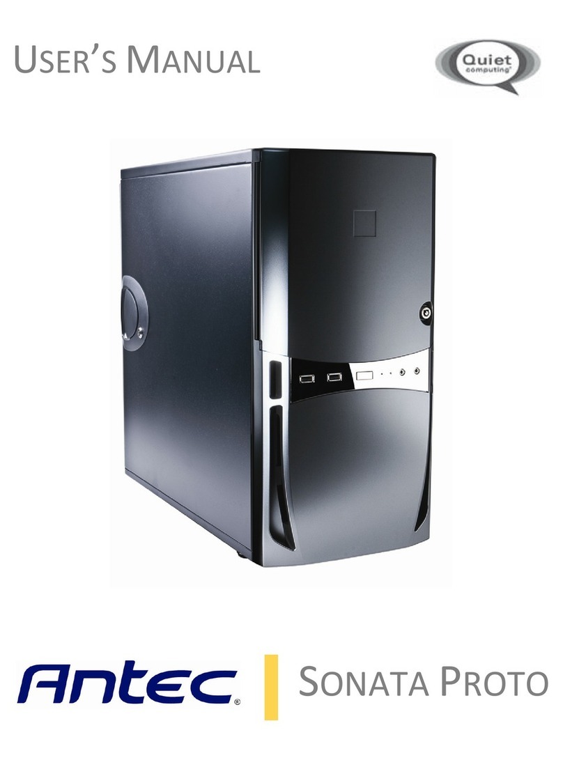
Antec Sonata Proto User manual

Antec

Antec Sonata Proto User manual

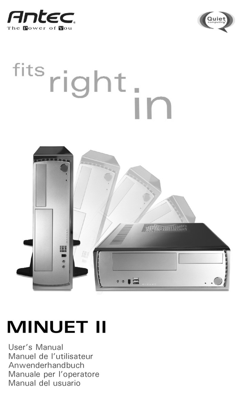
Antec MINUET II User manual

Antec

Antec MINUET II User manual

Antec ISK 310-150 User manual

Antec

Antec ISK 310-150 User manual

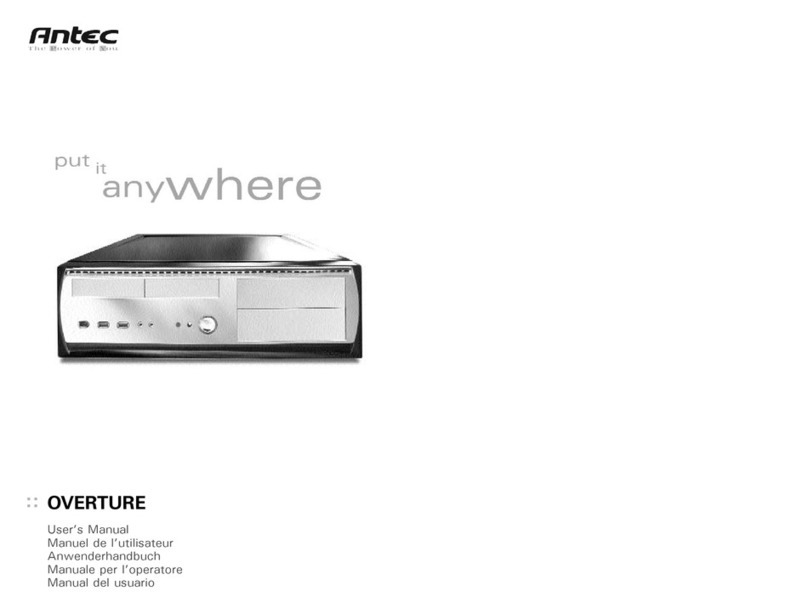
Antec OVERTURE User manual

Antec

Antec OVERTURE User manual

Antec Sonata Elite User manual

Antec

Antec Sonata Elite User manual

Antec SLK3700-BQE User manual

Antec

Antec SLK3700-BQE User manual

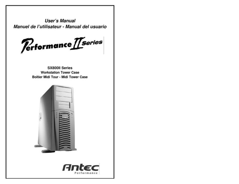
Antec SX800II Series User manual

Antec

Antec SX800II Series User manual

Antec ISK 110 VESA User manual

Antec

Antec ISK 110 VESA User manual

Antec Sonata Elite User manual

Antec

Antec Sonata Elite User manual

Popular Desktop manuals by other brands

HP Kayak XW A2-U2-W2 manual

HP

HP Kayak XW A2-U2-W2 manual

Dell INSPIRON Inspiron 1100 owner's manual

Dell

Dell INSPIRON Inspiron 1100 owner's manual

Lenovo ThinkCentre A51p Hardware

Lenovo

Lenovo ThinkCentre A51p Hardware

Lenovo J205 Guia do usuário

Lenovo

Lenovo J205 Guia do usuário

MAXDATA Ultra Small Desktop user manual

MAXDATA

MAXDATA Ultra Small Desktop user manual

Lenovo ThinkCentre A61e Brukerhåndbok

Lenovo

Lenovo ThinkCentre A61e Brukerhåndbok

HP Compaq Evo d510 SFF Hardware reference guide

HP

HP Compaq Evo d510 SFF Hardware reference guide

AXIOMTEK tBOX311-820-FL Series user manual

AXIOMTEK

AXIOMTEK tBOX311-820-FL Series user manual

Lenovo ThinkCentre Edge 92z Brukerhåndbok

Lenovo

Lenovo ThinkCentre Edge 92z Brukerhåndbok

Lenovo ThinkCentre M72e Användarhandbok

Lenovo

Lenovo ThinkCentre M72e Användarhandbok

Gateway 300X user guide

Gateway

Gateway 300X user guide

Ergotron 97-583-009 user guide

Ergotron

Ergotron 97-583-009 user guide

Supero SuperWorkstation 5038AD-T user manual

Supero

Supero SuperWorkstation 5038AD-T user manual

COMFILE P70 user manual

COMFILE

COMFILE P70 user manual

Lenovo 41X8111 hardware replacement guide

Lenovo

Lenovo 41X8111 hardware replacement guide

Dell OptiPlex 9020 manual

Dell

Dell OptiPlex 9020 manual

Production Basics 3000 Assembly manual

Production Basics

Production Basics 3000 Assembly manual

Streacom F7C installation guide

Streacom

Streacom F7C installation guide

manuals.online logo
manuals.online logoBrands
  • About & Mission
  • Contact us
  • Privacy Policy
  • Terms and Conditions

Copyright 2025 Manuals.Online. All Rights Reserved.