AST, AST-L, and AST-PLUS Models 7 Anthony Lifgtates, Inc.
800-482-0003 www.anthonyliftgates.com
CAUTION Anthony Liftgates
recommends not
riding the liftgate;
however, if the operation requires it, make sure your
footing is stable before raising or lowering the
platform. Always stand away from the edge. When on
the ground, always stand clear of the liftgate when it
is operating.
Do not attempt to maintain the liftgate
under the influence of drugs or alcohol.
Consult your doctor before using the
liftgate while taking prescription medications.
To prevent personal injury, clean up any
spilled fluids immediately. To avoid
tripping, do not leave tools or
components laying around in the work area.
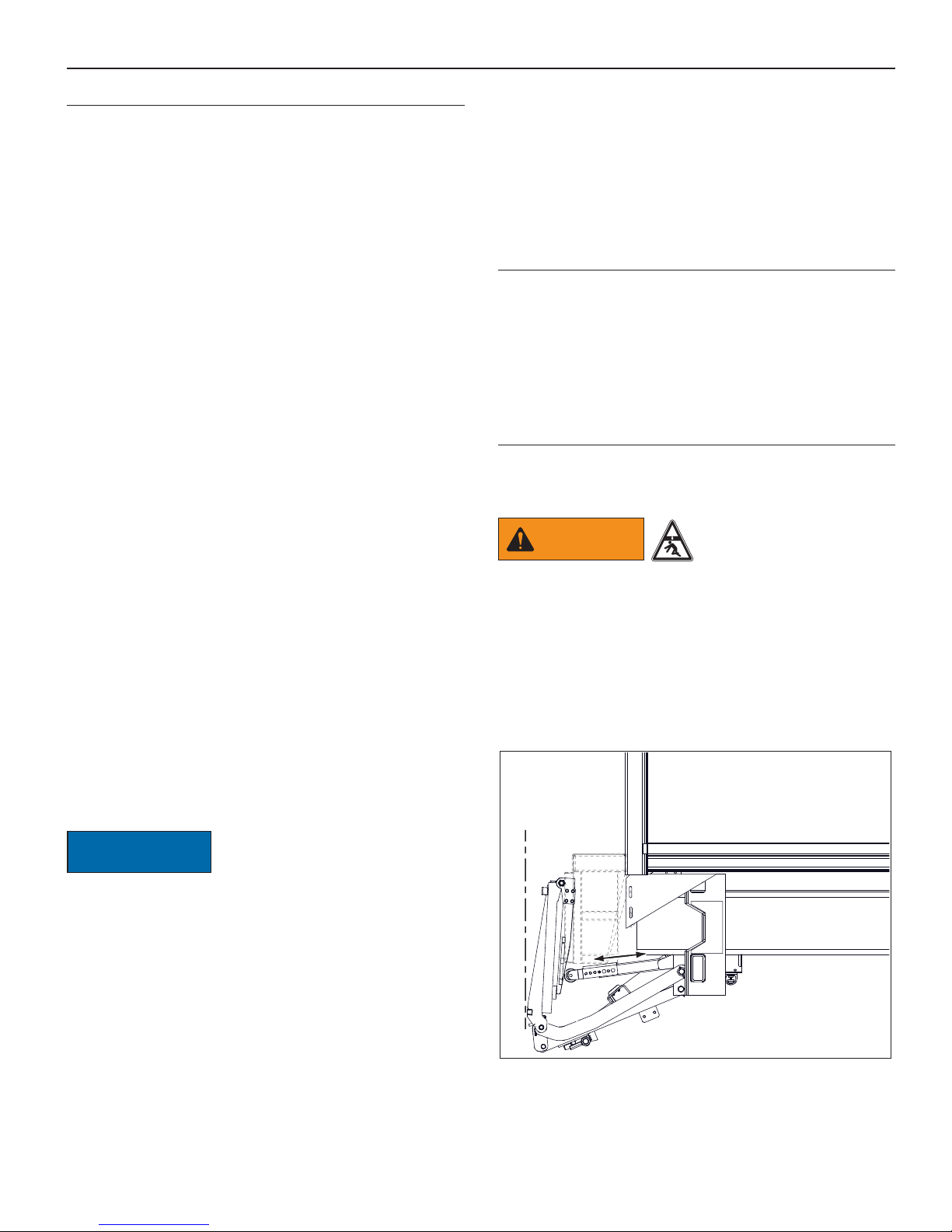
Failure to prevent the truck from moving
during the maintenance of the liftgate
could result in a serious crushing injury.
Always use/set the truck’s parking brake
and remove the ignition key before
servicing the liftgate. Failure to follow
this recommendation can result in injury.
Do not place hands or feet in pinch points.
Do not place your feet under the liftgate or
between the platform and floor extension.
CAUTION To prevent injury, the
liftgate and its related
components should only
be maintained by a qualified installer having knowledge
and skill in using a lifting device, a cutting torch, and
welding equipment.
N
I
NG
AR To prevent possible injuries due to improper
operation, make sure all decals are attached to
the liftgate and/or truck and are legible at all
times.
2.3.2 Equipment / Tools / Parts
CAUTION Do not operate this unit if
it is damaged. If you
believe the unit has a
defect, which could cause it to work improperly,
you should immediately stop and remedy the
problem before continuing.
Make sure the liftgate or truck will not be
damaged or made unsafe by the maintenance
or use of the liftgate.
Never secure the power cable to anything
which allows it to contact sharp edges, other
wiring, fuel tank, fuel lines, brake lines, air
lines, exhaust system, or any other object that could
cause the power cable to wear or be damaged. A cut
battery cable can cause sparks and/or component
damage resulting in loss of vehicle control, serious
injury, or even death.
CAUTION OEM
If replacement parts are
necessary, genuine
factory OEM replacement
parts must be used to restore the liftgate to the
original specifications. Anthony Liftgates will not
accept responsibility for damages as a result of using
unapproved parts. If non-OEM replacement parts are
used, the warranty will be voided.
2.3.3 Battery / Fuel Tank Safety
WARNING To prevent
serious
bodily injury,
keep sparks, lighted matches, and open flames away
from the top of the battery, because battery gas can
explode. Always follow all the manufacturers’ safety
recommendations when working around the truck’s
battery.
Take precautions to avoid sparks coming into
contact with the truck’s fuel tank, brake lines,
or other flammable components. Sparks can
cause an explosion of combustible materials, resulting
in serious injury or death.
2.3.4 Cutting Torch / Welding Safety
WARNING Take precautions to avoid
sparks from contacting
the truck’s fuel tank, brake
lines, or other flammable components. Sparks can
ignite combustible materials, resulting in serious
injury or death.
Always weld or use a cutting
torch in a well ventilated area and,
if in an enclosed area, vent the
fumes to the outside. Breathing welding smoke and
paint fumes can cause serious injury.
Always follow all State and Federal health and
safety laws and/or local regulations when using
an arc welder, mig welder, or cutting torch. Also,
follow all manufacturers’ safety guidelines. If other
people are present during the installation of the liftgate,
make sure the assembly area is shielded from their view.
To avoid eye injury during welding, always
wear a welding helmet with the proper lens to
protect your eyes.
To avoid eye injury while using a cutting torch,
always use eye protection with the proper lens
to protect your eyes.
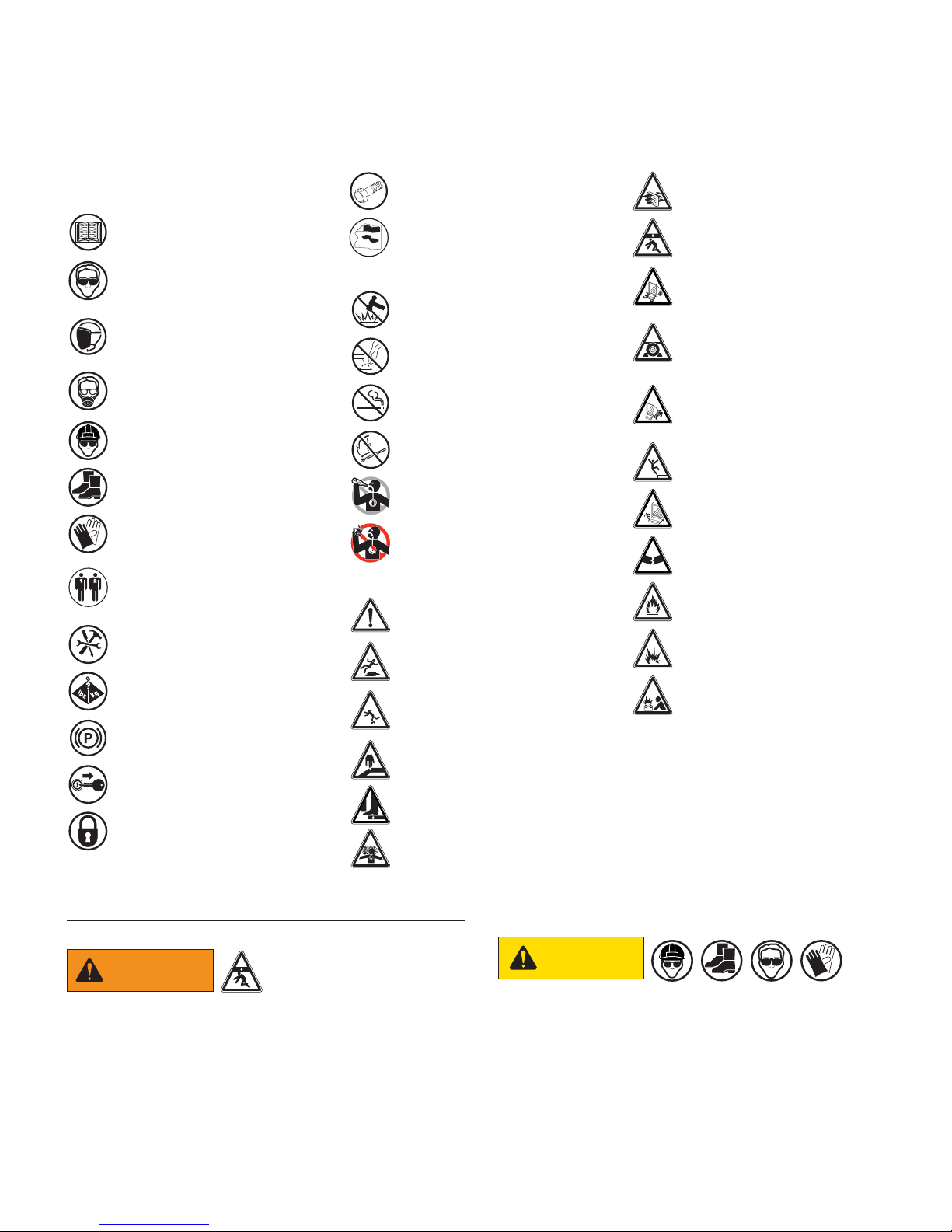
SAFETY
INSTRUCTIONS
Do not modify safety
devices. Do not
weld on the liftgate
assembly, except the adapter frame tube. Unauthorized
modifications may impair its function and safety.
Make sure all parts are in good working
condition and properly installed. Replace any
damaged parts immediately.