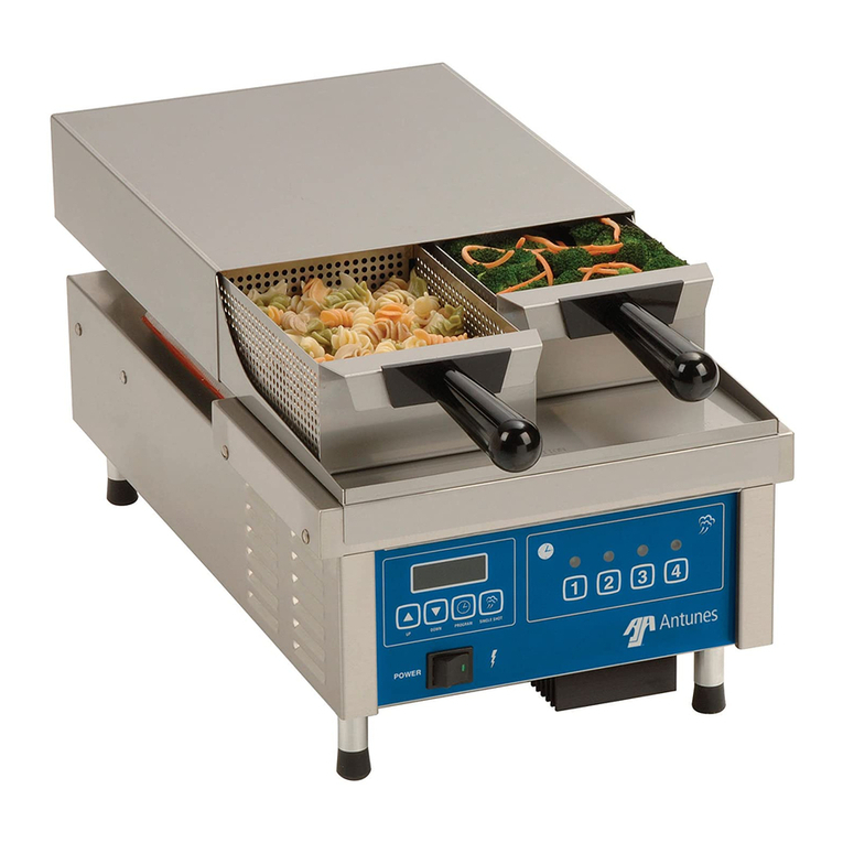
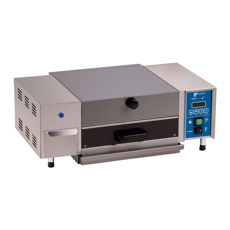
Antunes, AJ Roundup VS-200ASB User manual

VARIETY STEAMER
Models VS-200ASB & ADB
Owner’s Manual
P/N 1010649 Rev. E 03/07
MANUFACTURING
NUMBERS:
9100210
9100212
9100218
9100220
9100222
9100224
9100230
A
S
D
L
I
S
T
E
CM
O
I
N
N
I
T
A
T
C
T
I
S
L
US
E
D

2
VARIETY STEAMER
P/N 1010649 Rev. E 03/07
General
The Variety Steamer produces steam using plain
tap water for quick heating and reconstituting of food
items. Simple push button action delivers an impulse
of steam. Because the amount of steam is consistent,
it removes the guesswork and produces a uniform fin-
ished product from one operator to the next.
This manual provides the safety, installation and oper-
ating procedures for the Variety Steamer. We recom-
mend that all information contained in this manual be
read prior to installing and operating the unit.
Your Variety Steamer is manufactured from the finest
materials available and is assembled to Roundup’s
strict quality standards. This unit has been tested at
the factory to ensure dependable trouble-free opera-
tion.
OWNER INFORMATION
TABLE OF CONTENTS
IMPORTANT! Keep these instructions for future reference. If the unit changes owner-
ship, be sure this manual accompanies the equipment.
Warranty Information
Please read the full text of the Limited Warranty in this
manual.
If the unit arrives damaged, contact the carrier imme-
diately and file a damage claim with them. Save all
packing materials when filing a claim. Freight damage
claims are the responsibility of the purchaser and are
not covered under warranty.
The warranty does not extend to:
• Damages caused in shipment or damage as
result of improper use.
• Installation of electrical service.
• Normal maintenance as outlined in this manual.
• Malfunction resulting from improper maintenance.
• Damage caused by abuse or careless handling.
• Damage from moisture into electrical
components
• Damage from tampering with, removal of, or
changing any preset control or safety device.
Table of contents........................................................2
Owner Information .....................................................2
General......................................................................2
Warranty Information .................................................2
Service/Technical Assistance ....................................3
Model Designation.....................................................3
Important safety information.....................................4
Electrical Ratings at Listed Supply Voltages .............6
Specifications .............................................................6
Electrical Cord & Plug Configurations .......................6
Dimensions................................................................6
Capacities..................................................................6
Shipping Weight ........................................................6
Installation...................................................................7
Unpacking..................................................................7
Equipment Setup.......................................................7
Steaming Guide ..........................................................9
Operation...................................................................10
Operator Controls....................................................10
Operating Instructions .............................................11
Maintenance..............................................................12
Maintenance Schedule............................................12
Troubleshooting .......................................................16
Wiring Diagram.........................................................18
Replacement Parts ...................................................19
NOTES .......................................................................21
LIMITED WARRANTY ...............................Back Cover
3
VARIETY STEAMER
P/N 1010649 Rev. E 03/07
Model Designation
SB = Single Basket 20 oz.
DB = Dual Basket 10 oz. each
VS-200AXX
Service/Technical Assistance
If you experience any problems with the installation
or operation of your unit, contact your local Roundup
Authorized Service Agency. They can be found in the
service agency directory packaged with the equipment.
Fill in the information below and have it handy when
calling your authorized service agency for assistance.
The serial number is on the specification plate located
on the rear of the unit.
Purchased From:
Date of Purchase:
Model No.:
Serial No.:
Mfg. No.:
Refer to the service agency directory and fill in the
information below:
Authorized Service Agency
Name:
Phone No.:
Address:
Use only genuine Roundup replacement parts in this
unit. Use of replacement parts other than those sup-
plied by the manufacturer will void the warranty. Your
Authorized Service Agency has been factory trained
and has a complete supply of parts for this unit.
You may also contact the factory at 1-877-392-7854
or 1-630-784-1000 (outside the U.S and Canada) if
you have trouble locating your local authorized service
agency.
OWNER INFORMATION (continued)

4
VARIETY STEAMER
P/N 1010649 Rev. E 03/07
Throughout this manual, you will find the following safety words and symbols that signify important safety issues with
regards to operating or maintaining the Variety Steamer.
WARNING
GENERAL WARNING. Indicates informa-
tion important to the proper operation of
the equipment. Failure to observe may
result in damage to the equipment and/or
severe bodily injury or death.
WARNING
ELECTRICAL WARNING. Indicates infor-
mation relating to possible shock hazard.
Failure to observe may result in damage
to the equipment and/or severe bodily
injury or death.
CAUTION
GENERAL CAUTION. Indicates informa-
tion important to the proper operation of
the equipment. Failure to observe may
result in damage to the equipment.
WARNING
HOT SURFACE WARNING. Indicates
information important to the handling of
equipment and parts. Failure to observe
caution could result in personal injury.
IMPORTANT SAFETY INFORMATION
In addition to the warnings and cautions in this manual,
use the following guidelines for safe operation of the
unit.
• Read all instructions before using equipment.
• For your safety, the equipment is furnished with
a properly grounded cord connector. Do not
attempt to defeat the grounded connector.
• Install or locate the equipment only for its intend-
ed use as described in this manual. Do not use
corrosive chemicals in this equipment.
• Do not operate this equipment if it has a dam-
aged cord or plug; if it is not working properly, or
if it has been damaged or dropped.
• This equipment should be serviced by qualified
personnel only. Contact the nearest Roundup
authorized service facility for adjustment or repair.
• Do not block or cover any openings on the unit.
• Do not immerse cord or plug in water.
• Keep cord away from heated surfaces.
• Do not allow cord to hang over edge of table or
counter.
The following warnings and cautions appear
throughout this manual and should be carefully
observed.
• Turn the unit off, disconnect the power source
and allow unit to cool down before performing
any service or maintenance on the unit.
• The procedures in this chapter may include
the use of chemical products. These chemi-
cal products will be highlighted with bold
face letters followed by the abbreviated HCS
(Hazard Communication Standard). See
Hazard Communication Standard manual for
the appropriate Material Safety Data Sheets
(MSDS).
• The equipment should be grounded accord-
ing to local electrical codes to prevent the
possibility of electrical shock. It requires a
grounded receptacle with separate electrical
lines, protected by fuses or circuit breaker of
the proper rating.
• All electrical connections must be in accor-
dance with local electrical codes and any
other applicable codes.

5
VARIETY STEAMER
P/N 1010649 Rev. E 03/07
• WARNING ELECTRICAL SHOCK HAZARD.
FAILURE TO FOLLOW THESE INSTRUCTIONS
COULD RESULT IN SERIOUS INJURY OR
DEATH.
- Electrical ground is required on this appli-
ance.
- Do not modify the power supply cord plug.
If it does not fit the outlet, have a proper
outlet installed by a qualified electrician.
- Do not use an extension cord with this
appliance.
- Check with a qualified electrician if you
are in doubt as to whether the appliance is
properly grounded.
- The unit should be grounded according to
local electrical codes to prevent the pos-
sibility of electrical shock. It requires a
grounded receptacle with separate elec-
trical lines, protected by fuses or circuit
breaker of the proper rating.
• This equipment is to be installed to com-
ply with the basic plumbing code of the
Building Officials and Code Administrators,
Inc. (BOCA) and the Food Service Sanitation
Manual of the Food and Drug Administration
(FDA).
• Water pressure must not exceed 30 psi (2.1
kg/cm2or 207 kPa). Higher water pressures
may cause poor performance or flooding.
To reduce water pressure, install a water
pressure regulator and set water pressure
between 20-25 psi (1.4 - 1.7 kg/cm2or 138
- 172 kPa). To order a water pressure regula-
tor from your authorized service center, order
Roundup part no. 7000314.
• Do not clean this appliance with a water jet.
• Do not use a sanitizing solution or abrasive
materials. The use of these may cause dam-
age to the stainless steel finish.
• To ensure proper steaming characteristics,
some mineral deposits must be present on
generator casting. If, during cleaning, the
casting does become free of mineral deposits,
add plain tap water to casting and allow it boil
off. This will ensure proper steaming char-
acteristics by creating a thin layer of mineral
deposits on the casting.
IMPORTANT SAFETY INFORMATION (continued)
CAUTION
All electrical connections must be in accordance
with local electrical codes and any other appli-
cable codes.
WARNING
ELECTRICAL SHOCK HAZARD.
FAILURE TO FOLLOW THE INSTRUCTIONS IN
THIS MANUAL COULD RESULT IN SERIOUS INJU-
RY OR DEATH.
• Electrical ground is required on this appliance.
• Do not modify the power supply cord plug. If
it does not fit the outlet, have a proper outlet
installed by a qualified electrician.
• Do not use an extension cord with this appli-
ance.
• Check with a qualified electrician if you are in
doubt as to whether the appliance is properly
grounded.

6
VARIETY STEAMER
P/N 1010649 Rev. E 03/07
SPECIFICATIONS
Electrical Ratings at Listed Supply
Voltages
Capacities
VS-200ADB
• 10 oz. of frozen or thawed product in each of two
baskets. Note: Pastas must be precooked.
VS-200ASB
• 20 oz. of frozen or thawed product in one basket.
Note: Pastas must be precooked.
Shipping Weight
• 42 lbs. (19 kg)
Electrical Cord & Plug Configurations
Dimensions
12”
(305 mm) 21-1/2”
(546 mm)
10”
(254 mm)
3
4
1
12
13
2
5
7
9
10
8
6
11
POWER
READY
STEAM
Model &
Mfg. No.
Voltage Watts Amps Hertz
VS-200ASB
9100210 208-240 3800 18.3-15.8 50/60
VS-200ASB
9100212 230 3490 15.2 50/60
VS-200ADB
9100218 240 3000 12.5 50/60
VS-200ADB
9100220 208-240 3800 18.3-15.8 50/60
VS-200ADB
9100222 230 3490 15.2 50/60
VS-200ADB
9100224 240 3800 15.8 50/60
VS-200A
9100230 208-240 3800 18.3-15.8 50/60
Model &
Mfg. No.
Description Configuration
VS-200ASB
9100212&
9100222
CEE 7/7,
16 Amp., 250 VAC
(Assembly Only).
VS-200ADB
9100224
IEC-309, 16 Amp.,
250 VAC.,
Pin & Sleeve
Assembly Only).
VS-200ADB
9100210,
9100220
VS-200A,
9100230
NEMA 6-20P, 20
Amp., 250 VAC.,
Non – Locking
(Assembly Only).
VS-200ADB
9100218
UK BS 1363
13 Amp., 250
VAC.

7
VARIETY STEAMER
P/N 1010649 Rev. E 03/07
Unpacking
1. Remove unit and all packing materials from ship-
ping carton.
2. The unit should ship with:
• Variety Steamer
• Owner’s Manual
• Authorized Service Agency Directory
• Petro Gel Lubricant
• Water Inlet Hose Assembly
• Black Drain Tubing
NOTE: If any parts are missing or damaged, con-
tact Antunes Technical Service IMMEDIATELY at
1-877 392-7854 or 630-784-1000 in the U.S. and
Canada.
3. Remove all packing materials and protective cov-
erings from the unit.
4. Remove and wash all removable parts (baskets,
top housing, drip tray) in soap and water. Rinse
with clean hot water and allow to air dry.
5. Wipe all surfaces of the unit with a hot damp
cloth. Do NOT use a dripping wet cloth. Wring
out before use.
6. Re-install all removed parts.
INSTALLATION
Figure 1. Variety Steamer
CAUTION
All electrical connections must be in accordance
with local electrical codes and any other appli-
cable codes.
Equipment Setup
GENERAL
When placing the unit into service, pay attention to the
following guidelines:
• Make sure power to the unit is off and the unit is at
room temperature.
• Do not block or cover any openings on the unit.
• Do not immerse cord or plug in water.
• Keep cord away from heated surfaces.
• Do not allow cord to hang over edge of table or
counter.
• Raise the front legs so the unit is tilted slightly to
the rear (Figure 2).
ELECTRICAL
1. Place the unit on a sturdy, level table or other
work surface. Turn off the Rocker Switch before
proceeding.
2. Ensure that the line voltage corresponds to the
stated voltage on the units specification label and
power cord warning tag. Plug in the power cord.
Drip Tray
Basket Assy.
Top Cover Assy.
Lock Lever
Knob
3
4
1
12
13
2
5
7
9
10
8
6
11
POWER
READY
STEAM

8
VARIETY STEAMER
P/N 1010649 Rev. E 03/07
WARNING
BE SURE TO FOLLOW ALL GUIDELINES, PRO-
CEDURES, AND PRECAUTIONS LISTED IN THE
IMPORTANT SAFETY INFORMATION SECTION OF
THIS MANUAL.
Figure 2. Connecting Water Supply
PLUMBING
NOTE: Variety Steamer models are designed to
use cold tap water.
This unit requires a direct water hookup. A Water Inlet
Hose and Strainer Assembly (Figure 2) are supplied.
1. Turn off the water valve (not supplied) that pro-
vides water to the unit (Figure 2).
2. Connect the 1/4” (6.5 mm) I.D. flexible tubing to
the outlet side of the Water Pressure Regulator
and secure with the Worm Clamp as shown in
Figure 2.
NOTE: A Water Pressure Regulator (P/N 7000314)
must first be installed as shown in Figure 2.
Failure to do so will result in poor steaming and
possible flooding.
3. Turn water valve on.
CAUTION
This equipment is to be installed to comply with
the basic plumbing code of the Building Officials
and Code Administrators, Inc. (BOCA) and the
Food Service Sanitation Manual of the Food and
Drug Administration (FDA).
4. While holding over a bucket, press and hold the
“white” plastic tip on the Quick Disconnect insert
until good, steady water flow is noted. This will
purge all air out of the line. Release and note
the pressure on the Water Pressure Regulator
Gauge. If should read 20 PSI. If it reads more
or less, adjust the pressure by pulling the black
knob upwards and turning it clockwise to increase
(counter clockwise to decrease) the water pres-
sure. Push the knob down to lock it in place.
NOTE: When adjusting the knob, you must relieve
the existing pressure by pressing the “White”
plastic tip on the Quick Disconnect insert for 3 sec-
onds. The gauge will now show the new pressure
setting.
5. Push the Quick Disconnect insert into the fitting
at the rear of the unit until it “clicks.” (Figure 2).
NOTE: Incoming water is controlled by a solenoid
valve inside the electrical housing of the steamer.
6. Connect the black drain hose to the drip tray as
shown in Figure 2. Place the other end of the
drain hose in a drain or collection pan.
CAUTION
Water pressure must not exceed 30 psi (2.1 kg/
cm2or 207 kPa). Higher water pressures may
cause poor performance or flooding. To reduce
water pressure, install a water pressure regula-
tor, and set water pressure between 20-25 psi (1.4
- 1.7 kg/cm2or 138 - 172 kPa). To order a water
pressure regulator from your authorized service
center, order Roundup part no. 7000314.
INSTALLATION (continued)
Connect Quick
Disconnect
Insert Here
Front Legs
Raised
Slightly
Quick
Disconnect
Insert
Connect Black
Drain Hose Here
Inlet Hose & Strainer
Assy. (Supplied)
Water Pressure Regulator
& Strainer Assy. (P/N 7000314)
Shut Off Valve
(Not Supplied)
Cold
Water
Flow
Flexible Nylon Braided
1/4 " I.D. Tubing (Not Supplied)

9
VARIETY STEAMER
P/N 1010649 Rev. E 03/07
STEAMING GUIDE
The Variety Steamer makes it possible to expand a menu with just one piece of equipment. The Variety Steamer
produces a super-heated dry steam. This steam penetrates the product until the product’s temperature matches the
steam temperature. The guide below is an approximation of the number of steam shots and the time required to cook
the food item. Steam times may vary based on the state and quanitity of the food product.
PRODUCT
DESCRIPTION
DIAL SETTING TIME PRODUCT
DESCRIPTION
DIAL SETTING TIME
PreCooked
Items
VS-200 VS-350 Frozen Items VS-200 VS-350
Spaghetti 3 25 seconds Mixed
Vegetables
6 55 seconds
Rice 3 25 seconds Spaghetti 6 55 seconds
Egg Noodles 3 25 seconds Ravioli 12 1 minute, 55
seconds
Macaroni 3 25 seconds Tortellini 12 1 minute, 55
seconds
Ravioli 6 55 seconds Other
Tortellini 6 55 seconds Poached Eggs 18 2 minutes, 45
seconds
Roast Beef,
Sliced
2 15 seconds Bread Products 1-2 5-15 seconds
Shrimp 4 35 seconds
Tortilla Shell 1 5 seconds
Fresh Items
Shrimp 8 1 minute, 15
seconds
Broccoli 10 1 minute, 35
seconds
Products starting temperature is from a refrigerated state unless otherwise stated.
This is also based on a full 20 ounce basket or two individual 10 ounce baskets.

10
VARIETY STEAMER
P/N 1010649 Rev. E 03/07
OPERATION
Operator Controls
ROCKER SWITCH (POWER ON/OFF)
When the Rocker Switch is in the ON position, the
control board is activated and the green light on the
front panel lights up. A thermostat senses generator
temperature. If the generator temperature is below
350° F (176° C), power is applied to the generator until
setpoint is reached. The generator is constantly moni-
tored and power is regulated to maintain temperature
setpoint of 380° F (193° C).
YELLOW AND GREEN LIGHTS
The green light comes on when the Rocker Switch
(Power On/Off) is turned on. The green light is not lit
during the steaming cycle.
The yellow light comes on during the steaming cycle.
When the steaming cycle is complete, the yellow light
turns off, and an audio alarm sounds for 3 seconds.
CONTROL KNOB
The control knob setting determines the length of the
steaming cycle. Each number on the panel behind the
knob represents a ten second interval (1=10 sec; 2=20
sec; 3=30 sec; etc.) up to 130 seconds.
Example: During the steaming cycle, with the control
knob set to 3, the solenoid valve opens once every 10
seconds, applying 3 total shots of water that is con-
verted immediately into steam for the product.
NOTE: Each shot of steam is approximately 3/4 oz.
(25 milliliters) of water.
OPERATE SWITCH
When the operate button is pressed and released, Line
Voltage is supplied to the solenoid valve, the solenoid
valve opens, and water sprays onto the heated steam
generator. The water flashes immediately into live
steam and is forced up through the Black Manifold
Plate orifices.
LOCK LEVER
When in the full forward (towards operator) position,
the lock lever secures the Black Manifold Plate onto
the Steam Generator. Moving the lock lever to the full
rearward position unlocks the Black Manifold Plate,
allowing it to be removed for cleaning or servicing.
POWER
12
3
4
5
6
7
8
9
10
11
12
13
READY
STEAM
Green
Light
Yellow
Light
Operate
Switch
Lock Lever
Knob
Control
Knob
Rocker Switch
(power on/off)
Audio
Signal
Figure 3. Operating Controls
Lock Lever Knob
Locked Position
Figure 4. Lock Lever
HI-LIMIT THERMOSTAT
If the generator should overheat for any reason, the
Hi-Limit thermostat opens (trips) and cuts off power to
the generator. To reset this Hi-Limit, turn the unit off,
unplug the power cord, disconnect the rear water line
quick disconnect insert, and allow the unit to cool for 45
minutes. Place unit upside down and remove the four
(4) Control Panel screws (Figure 4). Carefully lift the
Control Panel upward and lay it on its side. Fully press
the red Hi-Limit Reset Button. Reassemble the unit. If
the Hi-Limit requires continuous resetting, contact your
Authorized Service Agency.

11
VARIETY STEAMER
P/N 1010649 Rev. E 03/07
Operating Instructions
1. Turn the Rocker Switch (Power On/Off) to ON.
2. Allow the unit to preheat for approximately 20-30
minutes.
NOTE: The green ready light will be on when the
unit is warming up.
NOTE: Do not push the operate button during
warm-up.
3. Rotate the Control Knob to position 3.
4. Press and release the operate switch. The green
ready light will go out and the yellow light will be
on indicating steaming is occurring.
NOTE: Allowing this first steaming cycle to finish
will purge air from the water line and ensure proper
operation.
5. Place product into the basket(s) and insert
basket(s) into top housing.
6. Turn the control knob to the desired timing cycle
and press the operate switch.
NOTE: Experiment by steaming product at differ-
ent settings until correct cycle for that product is
found.
7. When the audio alarm sounds, remove and
empty the basket(s).
8. At the end of the serving day or shift, turn off
the Rocker Switch and allow the unit to cool
before performing the procedures under “Daily
WARNING
To avoid injury, be careful when pulling basket
assembly out from unit. Be sure to allow steam
to escape before putting hands or face over the
steamer.
OPERATION (continued)
Maintenance” in the Maintenance section of this
manual..
Steaming Tips
• Pre-cooked pasta is easily reconstituted, and gives
you a hot product without the wetness of the normal
“dip” method.
• Experiment with your products and different steam-
ing times–a little more or less steam could change
the appearance/flavor.
• If you serve melted cheese on sandwiches, steam
is the perfect way to melt cheese.
• A steamed bun (which takes about 10-15 seconds)
says “Hot Sandwich” to your customer.
• Vegetables, rice and bread products can be recon-
stituted by steaming before serving which reduces
waste.
• Dinner rolls, muffins, even tortillas can be heated
completely and held without drying out the product.
• Use a low plate or pan when steaming to allow full
steam penetration and shorter cooking times.
• Condensation inside the steamer is normal, but
excess moisture indicates too much water is being
used.
• Heat meat and bread products apart from each
other, then combine in a sandwich. This will keep
the meat juices from soaking the bread.
• Finish off a special meal with a steamed hand
towel–hot without excess moisture.

12
VARIETY STEAMER
P/N 1010649 Rev. E 03/07
DAILY CLEANING
1. Turn the Rocker Switch (Power On/Off) to OFF.
Unplug the power cord and allow the unit to cool
down before proceeding.
2. Check the rear water quick disconnect fitting and
all hose clamp connections for leakage. If leak-
age is apparent, tighten all clamps or replace
part(s) if necessary.
3. Remove the basket(s), top cover housing assem-
bly, and the drip tray, wash them in hot soapy
water, rinse and allow to air dry.
4. Remove the Black Manifold Plate by slightly lifting
and sliding the Locking Lever (on the right side
of the unit) towards the rear, carefully remove
the plate and remove the large black O-ring from
the plate. Remove the diffuser plate, remove
the spray tube by carefully lifting the loose end
and gently twisting and pulling it out of the steam
generator hole. Take a suitable 1/16” punching
tool (such as a large paperclip) and fully insert
it through all 12 orifices in the black mani-
fold as well as through the six orifices in the
spray tube. This will assure that the orifices are
not obstructed with debris. Wash all items in hot
soapy water, rinse, and allow them to air dry.
5. Reinstall the spray tube into the steam generator
hole and reinstall the diffuser plate.
6. Lightly apply some Petro Gel (supplied) onto the
large black O-ring and reinstall the O-ring onto
the manifold plate (this will allow the manifold
plate to seat easily onto the steam generator).
Hold the manifold plate up to a light and verify
that light is visible through all of the orifices. If so,
seat the manifold fully onto the generator and pull
the locking lever forward to lock the plate.
7. Check that the Water Pressure Regulator is cor-
rectly set at 20-25 PSI (1.4 to 1.7 kg/cm2 or 138-
172 kPa.)
8. Reinstall all parts and accessories. Plug power
cord into electrical outlet.
MAINTENANCE
WARNING
Turn the unit off, disconnect the power source
and allow the unit to cool down before performing
any service or maintenance on the unit.
Maintenance Schedule
NOTE: Frequency of cleaning is determined by
water conditions, usage and water filter systems.
CAUTION
Do not use a sanitizing solution or abrasive mate-
rials. The use of these may cause damage to the
stainless steel finish.
CAUTION
If a chemical cleaner is used, be sure it is safe to
use on cast aluminum. Observe all precautions
and warnings on product label.
CAUTION
Unplug power cord before moving and servicing
this appliance.
CAUTION
Failure to regularly and/or properly clean this
equipment may damage it or cause the user bodi-
ly injury
CAUTION
Chlories or phosphates in cleasnsing agents such
as bleach, sanitizers, degreasers, or detergents
could cause permanent damage to the sainless
steel equipmenet. The damage is ususally in the
form of discoloration, dulling of metal surface fin-
ish, pits, voids, holes, or cracks. This damage is
permanent and is not covered by warranty. The
following tips are recommended for maintenance
of your stainless steel equipment:
• Always use a soft, damp cloth for cleaning,
rinse with clear water, and wipe dry. When
required, always rub in the direction of the
metal polish lines.
• Routine cleaning should be done daily using
soap, ammonia detergent, and water.
• Stains and sopts should be sponged using a
vinegar solution.
• Finger marks and smears should be removed
using soap and water.
• Hard water spots should be sponged using a
vinegar solution.

13
VARIETY STEAMER
P/N 1010649 Rev. E 03/07
MONTHLY CLEANING
Your steamer utilizes an open steam generator. Water
sprayed onto the generator surface flashes into steam
immediately, but the minerals in the water do not
steam; they stay on the generator surface. A small
amount of calcium/mineral deposits are needed for
proper operation, but a build-up of excessive calcium/
mineral deposits causes poor steaming efficiency,
excessive moisture (wet steam), and will eventually
retard the steaming action completely.
1. Turn the Rocker Switch (Power On\Off) to OFF.
Unplug the power cord and allow the unit to cool
down before proceeding.
2. Perform the steps under Daily Cleaning, but DO
NOT reassemble the unit.
3. With the unit cool, use a NON-ABRASIVE brass
wire brush and/or scraper to loosen and remove
the excessive calcium/mineral deposits from the
generator surface (Figure 5). Wipe the generator
with a clean, damp cloth and reassemble the unit.
NOTE: If the deposits are still excessive and/or dif-
ficult to remove, see Steps 4 through 10.
4. Pour delimer solution (not supplied) onto the
generator surface. Be sure to follow the delimer
manufacturer’s instructions for proper mixture and
use.
MAINTENANCE (continued)
CAUTION
If a chemical cleaner/delimer is used, be sure it is
safe to use on cast aluminum. Observe all pre-
cautions and warnings on the product label.
5. Using a sponge or dry towel, remove the delimer
solution from the generator surface, then rinse
with clear water.
NOTE: To ensure proper steaming characteristics,
some calcium/mineral deposits must be present
on the generator surface. If during cleaning, the
surface becomes free of calcium/mineral deposits,
add plain tap water to the surface and allow it to
boil off. If necessary, repeat this several times in
order to formulate a thin coating of calcium/mineral
deposits.
NOTE: In soft water areas, it may be necessary to
add a small amount of lime to the generator surface
to “season” it. This will ensure proper steaming
characteristics by formulating a thin coating of
calcium/mineral deposits on the generator surface.
Seasoning mixture consists of 3/4 ounce (25ml/
25cc) of baking soda, 3/4 ounce (25 ml/25cc) of
lime, and 1 quart (950ml/950cc) of water. Stir mix-
ture and pour 1/4” deep onto hot generator surface.
After mixture is converted to seam, the remaining
loose powder can be removed.
6. Plug the power cord into the appropriate outlet.
7. Turn the Rocker Switch (Power On/Off) to ON and
allow the unit to warm up for 30 minutes.
8. Set the Control Knob to “3” and push the Operate
Button to run a 30 second cycle of steam. This
will purge any remaining delimer residue from
the generator surface.
9. Turn the Rocker Switch (Power On/Off) to OFF.
10. Reinstall all parts and accessories.

14
VARIETY STEAMER
P/N 1010649 Rev. E 03/07
MAINTENANCE (continued)
CHECKING AND CLEANING THE WATER STRAINER
The Water Strainer protects your equipment from any
foreign debris in the water line that could get into the
food, damage the unit’s solenoid (causing the unit to
leak or flood) and protect from interference with the
equipment’s proper and consistent operation
To ensure proper and consistent steaming results,
visually check the water pressure regulator gauge and
strainer cup regularly. If the pressure on the gauge has
dropped, visually check the clear, plastic strainer “cup”
and clean out the accumulated debris as follows.
1. Shut off the water supply valve to the unit,
unscrew the clear, plastic strainer “cup” and care-
fully remove the mesh strainer screen.
2. At the sink, gently flush all of the accumulated
debris from the strainer cup and mesh strainer.
Be especially careful not to damage the mesh
strainer screen.
3 Carefully place the mesh strainer screen into its
seat at the bottom of the clear, plastic cup and
confirm that the orange O-ring is properly seated
in its place before screwing the strainer cup and
top back together.
4. Purge the air out of the strainer and tubing by
disconnecting the male quick disconnect insert
from the equipment and, over a bucket, push the
“white” plastic tip in until there is good water flow.
5. Replace damaged or warn parts as needed.
6. Verify that the Water Pressure Regulator is set to
20-25 PSI (1.4-1.7 kg/cm2 or 138-175 kPa).
1/4
NPT
Item Part Description Qty.
No.
1 7000333 Water Line Strainer Kit 1
2 2040130 Male Adapter, barbed - 1/4” 2
3 7000334 Replacement Screen and O-ring Kit 1
4 2110104 Clamp, Worm (Not shown) 2
22
3
NOTE: Item 1 is made
up of items 2 - 4.

15
VARIETY STEAMER
P/N 1010649 Rev. E 03/07
MAINTENANCE (continued)
Figure 5. Variety Steamer Components
Top Cover Assy. (1)
Black Manifold Plate (2)
Drip Tray (4)
Diffuser (38)
Spray Tube (37)
O-ring (3)
Steam Generator
Black Manifold Orifices
Control Panel (32)
Hi-Limit
Thermostat (35)
Control Panel
Screws (59)
NOTE: Numbers in parenthesis corre-
spond with replacement parts lists.

16
VARIETY STEAMER
P/N 1010649 Rev. E 03/07
TROUBLESHOOTING
WARNING
To avoid possible personal injury and/or damage to the unit, inspection, test and repair of electrical equipment
should be performed by qualified service personnel. The unit should be unplugged when servicing, except
when electrical tests are required. Use extreme care during electrical circuit tests. Live circuits will be exposed.
Problem Possible Cause Corrective Action
Power On/Off switch is
turned on, but the Switch
Indicator Light is still off
and the unit is not heating
up.
The power cord is not correctly plugged
in.
Plug the power cord in correctly.
The power cord and/or electrical plug is
damaged.
Inspect electrical wire, plug, and recep-
tacle.
The main electrical panel circuit breaker
is off, or has been tripped.
Reset circuit breaker. Contact your main-
tenance person or Authorized Service
Agency if it trips again.
Switch is inoperable. Contact your maintenance person or
Authorized Service Agency for service.
The unit’s main electrical
panel circuit breaker trips.
Damaged receptacle, plug, or cord; a
loose connection or an internal compo-
nent failure.
Turn the unit off, allow it to cool to room
temperature, and then restart the unit.
Contact your maintenance person or
Authorized Service Agency if condition
repeats.
Power On/Off switch is
turned on, the switch indi-
cator light is on, but the
unit is not heating up.
Hi-Limit thermostat is tripped. Reset the Hi-Limit according to the
Operation section of this manual. If it
requires continuous resetting or repair,
contact your maintenance person or
Authorized Service Agency for service.
Inoperable Thermostat.
Inoperable Generator.
Loose/burnt wiring.
Unit heats but there is lit-
tle or no steam produced
and/or
The product requires more
steaming than usual.
Water Line valve is closed. Check that the Water Line Valve is open.
Filter Strainer is restricted. Check and clean the Filter Strainer as
described in the Maintenance section of
this manual.
Quick Disconnect is not fully engaged at
rear of unit or is damaged.
Remove and re-engage the Quick
Disconnect Insert firmly until a “click” is
heard. Replace if damaged.
Low or no water pressure in water line. Remove the Quick Disconnect Insert from
the rear of the unit. While holding over a
bucket, press the “white” plastic tip. Strong
Water flow should be noted. If so, recon-
nect firmly into unit. If
Spray Tube is restricted. Remove and clean the Spray Tube accord-
ing to the Daily Maintenance procedures
found in this manual.
Black Manifold orifices are restricted. Remove and clean the Black Manifold
according to the Daily Maintenance proce-
dures found in this manual.
Unit is not being cleaned daily and/or
properly.
Clean unit Daily according to the Daily
maintenance procedures found in this
manual.
Improper water pressure to unit. Verify that a Water Pressure Regulator is
installed and set to 20-25 PSI.

17
VARIETY STEAMER
P/N 1010649 Rev. E 03/07
TROUBLESHOOTING (continued)
Problem Possible Cause Corrective Action
Unit heats but there is little
or no steam produced
and/or
The product requires more
steaming than usual.
(Continued)
Insufficient or excessive calcium/mineral
buildup on generator surface.
Verify that a thin layer of calcium/mineral
deposits is present on the Generator sur-
face. Refer to the Maintenance section of
this manual.
Black Manifold O-ring is worn, damaged,
or missing.
Replace the Black Manifold O-ring if worn,
damaged, or missing.
Low Generator temperature. Verify Generator surface temperature is at
least 380° F (193° C),
Steam leaks out of the
sides of the unit.
Black Manifold O-ring is damaged or
missing.
Replace the Black Manifold O-ring if worn,
damaged, or missing.
Black Manifold is difficult
to remove or re-install
onto the Generator.
Black Manifold not being removed and
cleaned daily as required.
Remove and Clean the Black Manifold
Daily according to the Maintenance section
of this manual.
Black Manifold O-ring is damaged or
worn.
Replace the Black Manifold O-ring if dam-
aged or worn.
Black Manifold O-ring is not being lubri-
cated daily with Petro Gel.
Lubricate the Black Manifold O-ring daily
according to the Maintenance section of
this manual.
Unit floods over night
and/or continues to steam
even when just in ready
mode.
Solenoid valve is being held open by
debris from the building’s water line pip-
ing.
Attempt to flush the debris out of the valve
by operating the unit on a number of cycles
and then letting it rest. If the unit still
leaks, contact your maintenance person or
Authorized Service Agency.
There is no pre-strainer/filter on the water
line just before the unit.

18
VARIETY STEAMER
P/N 1010649 Rev. E 03/07
WIRING DIAGRAM
Pictorial Wiring Diagram

19
VARIETY STEAMER
P/N 1010649 Rev. E 03/07
REPLACEMENT PARTS
25
26
24
57
23
27
28
29
30
31
33
58
22
32
56
20
55
53
54
19
21
16
11
C
10
51
8
15
7
13
14
12
60
59
64
36
1
2
3
4
5
38 37
6
58
49
34
8
73
71
72
68
69
70
57
35
18
67 17
9
65
66
63
63
39 40
40
42
43
44
74

20
VARIETY STEAMER
P/N 1010649 Rev. E 03/07
1 0021042 Top Housing Assy. 1
2 0100180 Generator Manifold 1
3 0200121 O-Ring 1
4 0010336 Drip Tray Assy. 1
5 0100179 Generator, 3800W (240V) 1
0100259 Generator, 3000W (240V)
(Mfg. No. 9100218 only)
6 2020104 Drain Tube 1
7 040K103 Insulation Kit 1
8 0501139 Retainer, Generator 2
9 001K125 Lock Lever and Support Assy. 1
10 2100138 Ball Knob 1
11 0021044 Lever Support 1
12 2190102 Teflon Tube 4 1/2” 1
13 200K126 Generator Tube Kit 1
14 0020419 Solenoid Valve with Fittings 1
15 200K127 Inlet Tube Kit 1
16 208K106 Quick Disconnect Body 1
17 7000139 Quick Disconnect Insert 1
18 0010584 Inlet Hose Assy. with Strainer 1
19 0700452 Power Cord 6-20P 1
(Mfg. No. 9100210, 220, & 230)
0700453 Power Cord CEE 7/7 1
Mfg. No. 9100212 & 222)
0700437 Power Cord IEC-309 (Mfg 9100224) 1
0700556 Power Cord UK BS 1363 1
250 V, 13 A (Mfg. No. 9100218)
20 210K230 Leg Kit (Qty. 4) 1
21 0020443 Base 1
22 4050170 Pot. and Low Voltage
Wiring Harness 1
23 4020131 Audio Signal 1
24 1000955 Label, Control Panel 1
25 210K122 Adjustable Leg Kit (Qty. 4)
(Incl. No. 26) 1
26 210K108 Rubber Tip Kit (Qty. 4) 1
27 4010137 Rocker Switch, Power On/Off 1
28 2100123 Adjusting Knob 1
29 4010166 Switch, Operate 1
30 4060208 LED Light, Yellow (Steam) 1
31 4060179 LED Light, Green (Ready) 1
32 0021043 Control Panel 1
33 402K169 Solid State Control 1
34 403K157 Thermostat 1
35 4030162 Hi-limit Thermostat 1
36 0021046 Main Housing 1
37 0020269 Spray Tube 1
38 0500625 Diffuser 1
39 2100119 Large Basket Handle 1
40 2100240 Handle Guard, Black 1
42 2100107 Small Basket Handle 1
43 0010550 Large Basket Assy. 20 oz. 1
44 0010551 Small Basket Assy. 10 oz. 2
45 0010570 Rice Basket Assy. 10 oz.(not shown) 2
46 001K717 Egg Poach Basket Kit (not shown) 2
47 0700523 Wire Set (not shown) 1
48 2140116 Petrol Gel (not shown) 1
49 4060304 Terminal Block 1
50 306P104* Screw, Truss Hd., #6-32 x 1/4” SS 1
51 325P109* Bolt, Hex Hd., 1/4-20 x 1/2” 1
52 325P134* Setscrew, 1/4-20 x 3/4” 1
53 308P115* Screw, Pan Hd., #8-32 x 3/8” SS 1
54 040P112* Strain Relief 1
55 308P143* Nut, Hex, KEPS, #8-32 1
56 310P109* Screw, Pan Hd., #10-32 x 3/8” SS 1
57 306P113* Screw, Round Hd., #6-32 x 5/8” 1
58 306P116* Nut, Hex, #6-32 1
59 308P103* Screw, Truss Hd., #8-32 x 1/4” SS 1
60 308P128* Screw, Binder Hd., Brass,
#8-32 x 1/4” 1
61 020P117* O-Ring, 5/16” I.D. 1
62 308P110* Screw, Binder Hd., Nickel,
#8-32 x 5/16” 1
63 338P102* Bolt, Carriage, 3/8-16 x 3/4” SS 1
Item Part Description Qty.
No.
Item Part Description Qty.
No.
REPLACEMENT PARTS (continued)
This manual suits for next models
1
Table of contents
Other Antunes, AJ Electric Steamer manuals
Popular Electric Steamer manuals by other brands

Market Forge Industries
Market Forge Industries ST-6-TGG Installation, operation and maintenance manual

Hamilton Beach
Hamilton Beach Digital Simplicity manual

Robusta
Robusta SLENDER instruction manual

Cuisinart
Cuisinart STM-1000A Series INSTRUCTION AND RECIPE BOOKLET

Toastmaster
Toastmaster Steam Heat EST7 owner's manual

Sinbo
Sinbo SFS 5703 manual