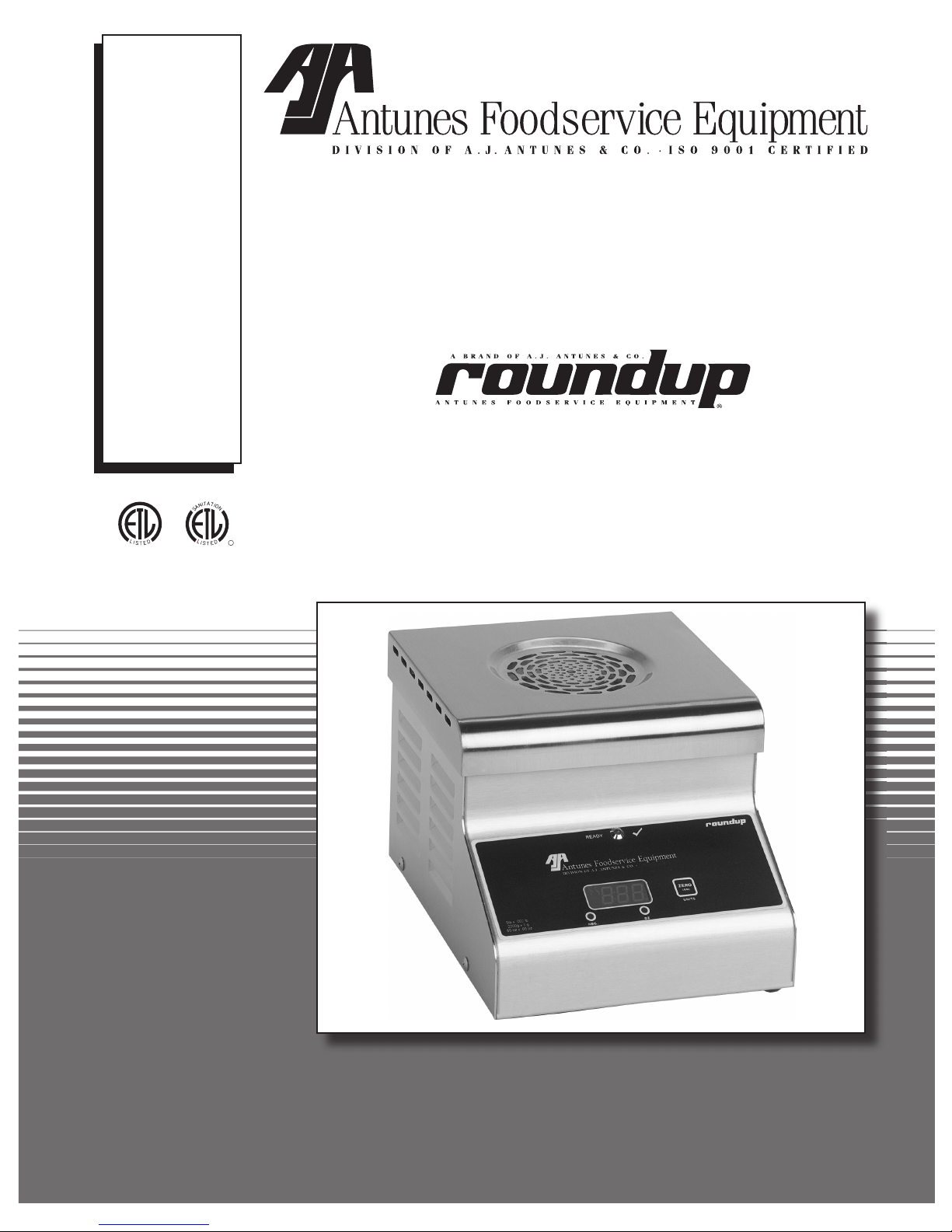
STS-200 STEAMER/SCALE
2P/N 1010853 Rev. C 09/04
Arby’s
STS-200 STEAMER/SCALE
3
P/N 1010853 Rev. C 09/04
Arby’s
General
The STS-200 Steamer/Scale produces steam using
plain tap water for quick steaming of sliced meats.
Simple push button action delivers a consistent impulse
of steam. Because the amount of steam is consistent,
it removes the guesswork and produces a uniform fin-
ished product from one operator to the next.
This manual provides the safety, installation, and oper-
ating procedures for the Steamer/Scale. We recom-
mend that all information contained in this manual be
read prior to installing and operating the unit.
Your Steamer/Scale is manufactured from the finest
materials available and is assembled to Roundup’s
strict quality standards. This unit has been tested at
the factory to ensure dependable trouble-free opera-
tion.
Warranty Information
Please read the full text of the Limited Warranty in this
manual.
OWNER INFORMATION
TABLE OF CONTENTS
IMPORTANT! Keep these instructions for future reference. If the unit changes owner-
ship, be sure this manual accompanies the equipment.
If the unit arrives damaged, contact the carrier imme-
diately and file a damage claim with them. Save all
packing materials when filing a claim. Freight damage
claims are the responsibility of the purchaser and are
not covered under warranty.
The warranty does not extend to:
• Damages caused in shipment or damage as
result of improper use.
• Installation of electrical service.
• Normal maintenance as outlined in this manual.
• Malfunction resulting from improper maintenance.
• Damage caused by abuse or careless handling.
• Moisture damage to electrical components.
• Damage from tampering with, removal of, or
changing any preset control or safety device.
Owner Information .....................................................2
General......................................................................2
Warranty Information .................................................2
Service/Technical Assistance ....................................3
Important Safety Information ....................................3
Specifications ............................................................5
Electrical Cord & Plug Configurations .......................5
Electrical Ratings.......................................................5
Model Designation.....................................................5
Dimensions................................................................6
Installation...................................................................7
Unpacking ....................................................................7
Equipment Setup..........................................................7
Installation Instructions for Dual Water Pressure
Regulator Kit P/N 7000418.........................................9
General......................................................................9
Installing the Dual Water Pressure Regulator ...........9
Checking and Cleaning the Water Strainer............ 10
Adjusting the Water Pressure Regulator ................ 10
Installation Instructions Optional Water Installation
Kit P/N 7000420 ........................................................12
General................................................................... 12
Installation .............................................................. 12
Installation Instructions for Air Bulb Switch
Kit P/N 7000419 ........................................................14
General................................................................... 14
Replacing the Air Bulb Switch ................................ 14
Operation...................................................................16
Operating Instructions ............................................ 16
Calibrating the Steamer/Scale................................ 16
Rotary Switch Settings ........................................... 17
Maintenance..............................................................18
Cleaning the STS-200 During Daily Use................ 18
Cleaning the STS-200 Steamer/Scale Daily .......... 19
Weekly Maintenance .............................................. 19
Cleaning the Water Inlet Tube................................ 20
Checking/Cleaning the Water Strainer Monthly ..... 20
Weekly- Testing the STS-200 for
Weighing Accuracy................................................ 21
Message Codes...................................................... 21
Troubleshooting .......................................................21
Error Codes ............................................................ 22
Technical Theory of Operation ............................... 26
Technical Theory of Operation ...............................26
Replacement Parts ...................................................28
Wiring Diagram.........................................................36
NOTES .......................................................................37
Limited Warranty ......................................Back Cover