Anua Purasys sbr User manual

Reference Manual
Only models bearing the NSF logo
and designated PS1-XX are certified to NSF/ANSI Standards 40 and 245
Call: 336-547-9338 or visit: anuainternational.com © 2016 Anua 6-2016
Anua_PuraSys_RefManual_063016_Anua_PuraSys_RefManual 6/29/16 4:41 PM Page 1

Reference Manual
T ble of Contents
1.0 What’s in the Box? 2
2.0 Anatomy of an SBR 2
2.1 Process Overview 3
3.0 System Design 3
3.1 Pretreatment or Septic Tank Sizing 3
3.2 Reactor Chamber or Tank Sizing 4
3.3 Clear Water Pump 4
3.4 Emergency Storage Volume Calculations 4
4.0 System Installation 7
4.1 Site Clearance 7
4.2 Pretreatment or Septic Tank and Reactor Chamber 7
4.3 Reactor Tank 8
4.4 Site Restoration 8
5.0 System Wiring 9
5.1 Power Supply 9
6.0 Reactor Venting and Plumbing 9
6.1 Reactor Venting 9
6.2 Reactor Plumbing 10
7.0 System Startup 10
8.0 Smart Control Panel Overview 10
9.0 Maintenance 11
9.1 Clarity Test 11
9.2 Sludge (Biomass) 11
10.0 Troubleshooting 12
11.0 Owner Use 13
12.0 Owner’s Duties 13
13.0 Owner Checklist 14
14.0 Warranty for PuraSys SBR 14
If you require further information, please contact customer service at:
P.O. Box 77457 reensboro, NC 27417
T: 336-547-9338 F: 336-547-8559
Call: 336-547-9338 or visit: anuainternational.com © 2016 Anua 6-2016
Anua_PuraSys_RefManual_063016_Anua_PuraSys_RefManual 6/29/16 4:41 PM Page 2

2
Call: 336-547-9338 or visit: anuainternational.com
Reference Manual
1.0 Wh t’s in the Box?
PuraSys SBR Models PS1-4 through PS1-8 (≤800 gpd) include (1) Novair 200 Aerator.
PuraSys SBR Models PS1-9 through PS1-14 (≤1,400 gpd) include (1) Novair 600 Aerator.
Additionally, each system comes in a box with the following components:
2.0 An tomy of n SBR
Siphon/sludge return
Clear water
discharge
Float switches
System can be
a single tank or
multiple tanks
Pretreatment
(1 chamber) Reactor
(1 chamber)
Controls
Optional controls add-on
Junction box
Siphon/sludge pump
Clear water pump
Float switch
PVC stand kit, aerator
PVC stand kit, pump
Wire tie
1.25" Schedule 40 union
Float bracket
Stainless Steel screw for stand mounting clamp
Siphon pipe pre-drilled with 3/8" holes
Stand mounting clamp
J hook wire holder
Stainless clamp
Pump mounting clamp
Aerator mounting clamp
Air vent
Sonic dampener 4", aerator
Vibration dampener 1” x 1.5”, aerator
(1) Anua
(1) Autodialer
(1) Anua w/2 float grips, 2 pump grips, & 1 aerator grip
(1) Goulds STS31
(1) Goulds STS31 (see note 3)
(2) Alderon (included with panel)
(1) Anua A-STAND-PS
(2) Anua P-STAND-PS
(10)
(2) for PVC pipe
(2) Sim/Tech STF-FHPB 1.25"
(9) For Sim/Tech STF-FHHW 1.25"
(1) 1.25", cut length per tank dimensions
(3) Sim/Tech STF-FHHW 1.25"
(2) Sim/Tech STF-JHOO
(4) 2.5” SS Clamp
(2) MTG-CLMP-SS-AS
(1) MTG-CLMP-SS-PS
2” Banjo threaded air vent
(1)
(1)
N TE: 1. REACT R TANK MUST BE VENTED! Use vented riser lid or provided vent piping with vent guard.
2. Use 1.25” Schedule 40 PVC piping for sludge pump and clear water pump.
3. For other clear water pump options, contact distributor or Anua.
Figure 1
Anua_PuraSys_RefManual_063016_Anua_PuraSys_RefManual 6/29/16 4:41 PM Page 3

3
Call: 336-547-9338 or visit: anuainternational.com
Reference Manual
2.1 Process Overview
1. Filling
Water is moved from Pretreatment to Reactor.
2. Reaction
A mixture of aeration, pausing, and mixing
breaks down BOD and allows for nitrification
and denitrification within the same tank.
3. Sedimentation
Nothing moves in the Reactor and the
solids settle to the bottom, leaving
clear water at the top.
4. Clear Water Discharge
Clear water is pumped from
the Reactor to the discharge point.
5. Sludge Return
Excess sludge is returned from the Reactor
to the pretreatment to maintain a proper sludge age.
3.0 System Design
3.1 Pretre tment or Septic T nk
The pretreatment tank, riser(s), and lid(s) must be watertight. The minimum volume
shall be 250 gallons per bedroom. Alternatively, the size and configuration shall be in
accordance with State or Local requirements for septic tank sizing.
Pretreatment or Septic Tank
(1 chamber tank. Examples include septic tank, pump tank, or
holding tank. For 2 chamber configuration, contact Anua)
Reactor Chamber
or Tank
Figure 2 The SBR Process
Figure 3
Anua_PuraSys_RefManual_063016_Anua_PuraSys_RefManual 6/29/16 4:41 PM Page 4

4
Call: 336-547-9338 or visit: anuainternational.com
Reference Manual
3.3 Cle r W ter Pump
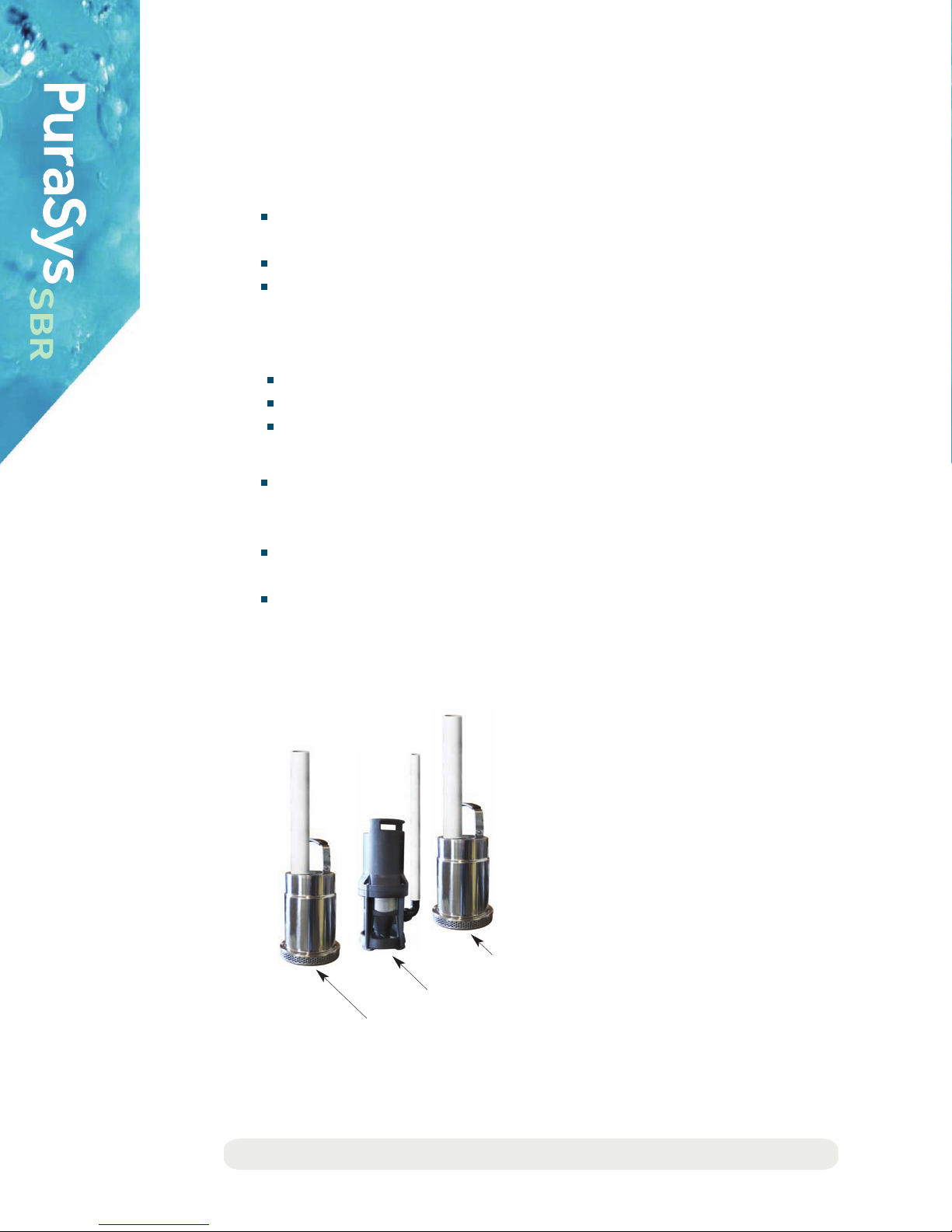
The clear water pump (discharge pump) is an integral part of the system. This is
advantageous since the SBR is essentially a primary tank, treatment unit, and pump
tank all-in-one. The pump provides timed dosing for a downstream component
such as a polishing filter or drainfield. The standard kit contains a typical 0.5 HP
effluent pump. A larger pump can be included in the kit where required. The clear
water pump can be used to discharge to the following:
Polishing unit such as the Puraflo peat fiber biofilter with optional pad dispersal
ravity trench or bed
Low Pressure Pipe (LPP) drainfield
Drip irrigation
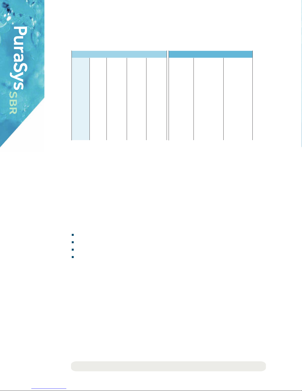
3.2 Pur Sys SBR Re ctor T nk Sizing
N TE: The minimum and maximum volumes in these tables are guidelines for standard kits.
The volumes can vary from the values in the table. Consult with Anua for alternate designs.
_________________________________________________
NSF Reactor Tank Sizing (gallons)
_________________________________________________
_________________________________________________
PS1-4 400 605 545 665
_________________________________________________________________________________________________________________________
PS1-5 500 756 681 832
_________________________________________________________________________________________________________________________
PS1-6 600 908 817 998
_________________________________________________________________________________________________________________________
PS1-7 700 1,059 953 1,165
_________________________________________________________________________________________________________________________
PS1-8 800 1,210 1,089 1,331
_________________________________________________________________________________________________________________________
PS1-9 900 1,361 1,225 1,497
_________________________________________________________________________________________________________________________
PS1-10 1,000 1,513 1,361 1,664
_________________________________________________________________________________________________________________________
PS1-11 1,100 1,664 1,497 1,830
_________________________________________________________________________________________________________________________
PS1-12 1,200 1,815 1,634 1,997
_________________________________________________________________________________________________________________________
PS1-13 1,300 1,966 1,770 2,163
_________________________________________________________________________________________________________________________
PS1-14 1,400 2,188 1,906 2,329
__________________________________________________
Model Minimum Maximum
Flow
(gpd)
Reactor
Tank Size
___________________________________________
Anua Recommended Reactor Tank Sizing (gallons)
___________________________________________
___________________________________________
400 240 320
__________________________________________________________________________________________________________
500 300 400
__________________________________________________________________________________________________________
600 360 480
__________________________________________________________________________________________________________
700 420 560
__________________________________________________________________________________________________________
800 480 640
__________________________________________________________________________________________________________
900 540 720
__________________________________________________________________________________________________________
1,000 600 800
__________________________________________________________________________________________________________
1,100 660 880
__________________________________________________________________________________________________________
1,200 720 960
__________________________________________________________________________________________________________
1,300 780 1,040
__________________________________________________________________________________________________________
1,400 840 1,120
_______________________________________________
Peak Design
Flow (gpd)
Minimum,
Approximate
Maximum,
Approximate
Table 1
Anua_PuraSys_RefManual_063016_Anua_PuraSys_RefManual 6/29/16 4:41 PM Page 5

5
Call: 336-547-9338 or visit: anuainternational.com
Reference Manual
3.4 Emergency Stor ge nd Al rm Conditions
PuraSys SBR controls the movement of effluent through the system in a timed
sequence of batches. PuraSys SBR incorporates a clear water discharge pump. Since
treated effluent is timed dosed from the system, adequate emergency storage
must be provided. This is typically provided in the pretreatment tank due to the
operational sequence of the controls. For a one tank, 2-compartment configuration,
the reactor chamber can be included in the emergency storage calculations.
1. ne Tank, 2-Compartment Configuration
The total emergency storage volume is calculated based on the available
volume in the pretreatment tank and the reactor chamber/tank above the
normal operating levels to the inside tank lid. Since the chambers are con-
nected via the air space above the baffle wall, volume in both chambers can
be counted for emergency storage. In some jurisdictions, the riser volume can
be counted for emergency storage. Emergency storage can be calculated as
follows:
Pretreatment tank: Determine the volume between the top siphon hole to
the top of the tank (inside lid).
Reactor chamber: Determine the volume between the high water alarm
and the top of the tank (inside lid).
If allowed per local jurisdiction, determine the volume in the risers.
Total storage volume = Pretreatment + Reactor + Risers
Emergency storage in typical two compartment tank
Figure 4
Anua_PuraSys_RefManual_063016_Anua_PuraSys_RefManual 6/29/16 4:41 PM Page 6

6
Call: 336-547-9338 or visit: anuainternational.com
Reference Manual
2. Two Tanks Configuration
The total emergency storage volume is calculated based on the available volume in the
pretreatment tank above the normal operating level to the inside tank lid. In some jurisdictions,
the riser volume can be counted for emergency storage. Emergency storage can be calculated
as follows:
Pretreatment tank: Determine the volume between the top siphon hole to the top of
the tank (inside lid).
If allowed per local jurisdiction, determine the volume in the risers.
Total storage volume = Pretreatment + Risers
3. Alarm Conditions
An alarm will trigger under the following conditions:
High water float activated in reactor chamber.
Aerator current <1 or no current.
Siphon/sludge pump current <1 or no current.
The operational sequence is outlined below:
If the clear water discharge pump fails or malfunctions, a high water condition will
occur in the reactor chamber. The high water condition will trigger the an alarm. The
high water alarm will suspend operation of the siphon/sludge pump.
If the current sensor does not read proper current to the aerator, an alarm will trigger.
The aerator alarm will suspend operation of the siphon/sludge pump.
If the current sensor does not read proper current to the siphon/sludge pump, an alarm
will trigger. At this point, this pump is not operational.
Aerator
Siphon/sludge pump
Clear water pump
Figure 5
Anua_PuraSys_RefManual_063016_Anua_PuraSys_RefManual 6/29/16 4:41 PM Page 7

7
Call: 336-547-9338 or visit: anuainternational.com
Reference Manual
4.0 System Inst ll tion
4.1 Site Cle r nce
Clear site vegetation as required (minimize site disturbance).
Provide sufficient access to proposed system.
4.2 Pretre tment or Septic T nk nd Re ctor Ch mber
Supply and install pretreatment tank and sewer pipe from the dwelling in accordance with
applicable State or Local regulations. The pretreatment tank must be watertight against
ground and/or surface water infiltration and exfiltration.
Install pretreatment tank on stable, compacted fill (e.g. stone ≤1” or similar material).
Pretreatment tank must be backfilled with suitable material as recommended by the
manufacturer. Backfill must be free of debris and large or sharp objects.
Install water tight risers over access ports to provide access for maintenance and sludge removal.
Install aerator stand, siphon/sludge pump stand, clear water discharge pump stand, and other
components in reactor chamber per installation checklist. The aerator, siphon/sludge pump,
clear water discharge pump, timer float, and high water alarm float heights are factory set.
Install siphon/sludge return line from the pretreatment compartment to the reactor chamber.
Secure the pre-drilled siphon pipe in the pretreatment tank with the top 3/8” hole at the
correct height as indicated in the design.
Connect the clear water pump discharge line to the drainfield in accordance with applicable
State or Local regulations.
Backfill and grade around
the pretreatment tank to
prevent infiltration of
surface water.
See PuraSys SBR
typical drawings for
further details on layout.
Installation Warning
Do not backwash a water
softener into the system.
Table 2 PuraSys SBR Pretreatment Tank Siphon Pipe Dimension
from Tank Bottom and Pump Out Requirements
_____________________________________________________________________
_____________________________________________________________________
36 14 9
________________________________________________________________________________________________________________________
38 15 10
________________________________________________________________________________________________________________________
40 16 10
________________________________________________________________________________________________________________________
42 17 11
________________________________________________________________________________________________________________________
44 18 11
________________________________________________________________________________________________________________________
46 18 12
________________________________________________________________________________________________________________________
48 19 12
________________________________________________________________________________________________________________________
50 20 13
________________________________________________________________________________________________________________________
52 21 13
________________________________________________________________________________________________________________________
54 22 14
_____________________________________________________________________
Liquid
Depth
(inches)
Siphon Pipe
90º Elbow Height from
Inside Tank Bottom
(inches)
Depth of Sludge
Requiring Tank
Pumping
(inches)
Combined Volume
of Scum & Sludge
Requiring Tank
Pumping
1/3 or 33%
N TE: For tank depths <36" or >54", please consult Anua.
Anua_PuraSys_RefManual_063016_Anua_PuraSys_RefManual 6/29/16 4:41 PM Page 8

8
Call: 336-547-9338 or visit: anuainternational.com
Reference Manual
4.3 Re ctor T nk (if applicable, for two tank systems)
Supply and install the reactor tank in accordance with applicable State or Local regulations. The
reactor tank must be watertight against ground or surface water infiltration and/or exfiltration.
Install reactor tank on stable, compacted fill (e.g. stone ≤1” or similar material).
Reactor tank must be backfilled with suitable material as recommended by the manufacturer.
Backfill must be free of debris and large or sharp objects.
Install water tight risers over access ports to provide access for maintenance and sludge removal.
Install aerator stand, siphon/sludge pump stand, clear water discharge pump stand, and
other components per installation checklist. The aerator, siphon/sludge pump, clear water
discharge pump, timer float, and high water alarm float heights are factory set.
Install siphon/sludge return line from the pretreatment tank to the reactor tank in accordance
with applicable State or Local regulations. The siphon/sludge return line must be adequately
supported to prevent damage during backfilling.
Secure the pre-drilled siphon pipe in the pretreatment tank with the top 3/8” hole at the
correct height as indicated in the design.
Connect the clear water pump discharge line to the drainfield in accordance with applicable
State or Local regulations.
Backfill and grade around the reactor tank to prevent infiltration of surface water.
4.4 Site Restor tion
The riser lids must be installed above grade with the ground landscaped to divert storm water
away from the area.
Backfill should be suitable, loose, workable material.
Backfill must be free of debris and large or sharp objects.
Compact backfill sufficiently to adequately prevent settlement.
Landscape (e.g. grass seed, sod, straw, landscape stone, xeriscape, etc.) the sloped backfill area
and any trench excavation
lines with a suitable indigenous seed variety or use other methods.
PROVIDE EROSION PROTECTION AS REQUIRED PER DESI N PLAN.
Installation Warning
If you are not using an air break on
the clear water pump discharge pipe,
then install a check valve!
Construction Warning
During construction, harmful
chemicals such as paint and
solvents can harm the system
microbes if dumped down the
drain. These items should not be
allowed into the treatment plant.
Anua_PuraSys_RefManual_063016_Anua_PuraSys_RefManual 6/29/16 4:41 PM Page 9

9
Call: 336-547-9338 or visit: anuainternational.com
Reference Manual
5.0 System Wiring
The cables are coded to match the connections between the
aerator, pumps, and float switches to the junction box and
control panel.
The smart control panel is housed in a NEMA 4X enclosure. The
wiring diagram and instructions are located inside the panel.
Incoming power must be 240V, 1 Phase and 120V, 1 Phase.
5.1 Power Supply
The system must be wired by a person qualified to do electrical
work per the applicable State or Local electrical code.
The control panel requires two separate incoming power
feeds as follows:
20A, 2 Pole, 240V breaker
20A, 1 Pole, 120V breaker
6.0 Re ctor Venting nd Plumbing
6.1 Re ctor Venting
Aerator must be supplied with fresh oxygen.
Direct aerator air tube into vent housing and cut to proper length to insure hose will rest inside
of vent housing without impeding air flow to aerator.
Air vent included in the kit is not required for use. However, air tube must exit to atmosphere in
order to obtain fresh oxygen to inject into aerator
Ensure the aerator is properly secured to the riser with the clip included in the kit.
Recommended
Surge Suppression
In order to add extra protection
to the control panel, the addition
of external surge suppression
is recommended.
The surge suppressor should be
attached in parallel to the
junction on the main power line.
Figure 6
Anua_PuraSys_RefManual_063016_Anua_PuraSys_RefManual 6/29/16 4:41 PM Page 10

10
Call: 336-547-9338 or visit: anuainternational.com
Reference Manual
6.2 Re ctor Plumbing
Siphon/sludge pump and clear water pump must be plumbed with quick disconnects.
Unions are included in the kit.
If you are not using an air break on the clear water pump discharge pipe, then install a check valve.
In cold weather climates subject to freezing, slope clear water pump pressure line for drainback
to reactor chamber/tank and do not install a check valve.
Ensure the pumps are properly secured to the riser with the clips included in the kit.
7.0 System St rtup
Once the system is installed, the pumps, aerator, and float switches must be tested to ensure
that they each work. The bottom float switch must be in the ‘up’ position in order to test the
clear water pump.
The tank(s) should be filled with water in order to verify tank(s)/risers watertightness. After
completion of the watertightness testing, the system should be started to check for any
plumbing leaks. When start-up is completed, the system can be left ‘on’. The system will
remain in vacation mode until water begins to flow from the facility.
8.0 Sm rt Control P nel Overview
The smart control panel is designed be simple and easy to operate. All key adjustments and
readings can be accessed through the four button keypad. Operational data is stored in the PLC.
The smart control panel optimizes the SBR process. The following settings can be adjusted:
Aeration time per cycle (min)
Fill pulse time (sec)
Sludge return time per cycle (sec)
Clear water pump timer settings (min)
The smart control panel records the
following information:
Siphon/sludge pump run time
Siphon/sludge pump cycle count
Clear water pump run time
Clear water pump cycle count
Aerator run time
Aerator cycle count
The controller display and setting
instructions are located inside the
panel. Mechanical components can be
manually operated using the HOA toggle switches located inside the smart control panel.
Setting 2 PM
1 Adjust
3 Steps
2 Fill
1 Aeration
3 Slu Ret
2 Sludge
1 Aerator
3 CWP
2 Errors
1 Record
3 Reset
2
Pumps
1
Maintain
3
Main Menu
Figure 7
Anua_PuraSys_RefManual_063016_Anua_PuraSys_RefManual 6/29/16 4:41 PM Page 11

9.0 M inten nce
Maintenance steps:
1. Check the smart control panel for alarms or for errors.
2. Check pretreatment tank and take a sludge reading (see right).
3. Open reactor chamber lid. Check for noxious odor and take a
sludge sample
4. If the system is in sedimentation mode and prior to clear water
discharge, you may be able to perform a clarity test
(see Section 9.1).
4. Manually test the pumps and aerator.
5. Make adjustments and take readings.
6. Replace cover and record maintenance.
7. ive a copy of the maintenance report to the system owner. File
the maintenance report with regulatory authority as required by law.
9.1 Cl rity Test
The clarity test may be used to visually determine effluent quality.
To perform the clarity test, the service provider places an eight-inch
disk with alternating black and white colored quadrants just above
the sludge blanket in the reactor chamber. Be careful not to disturb
the sludge blanket! If the disk is visible when the reactor chamber is
1/3 full, then the effluent quality passes the clarity test.
9.2 Sludge (Biom ss)
A mature system should have a healthy, one-foot layer
of sludge at the bottom of the reactor chamber. This
one-foot sludge layer is maintained at a constant level
due to the sludge pump portioning excess sludge back
to the pretreatment tank. A sludge reading requires a
tool, such as a Sludge Judge, that allows you to pull a
sample and see the sludge profile. If a recent aeration
event occurred, the service provider must wait about
30 minutes prior to obtaining a sludge sample.
Four things to take note of when looking at the
sludge:
1. Size
2. Color
3. Settleability
4. Volume (level)
11
Call: 336-547-9338 or visit: anuainternational.com
Reference Manual
Figure 8
Figure 9
Anua_PuraSys_RefManual_063016_Anua_PuraSys_RefManual 6/29/16 4:42 PM Page 12

10.0 Troubleshooting
Mechanical failure may be pumps, aerator, or float switches
Replace failed component
Test component for proper operation
Field Issue
Determine if there is a blockage or break in any lines.
Check for signs of high groundwater
Check for signs of damage by animals or insects
Check for signs of damage by any type of motor vehicle
Check for signs of damage by any plant or tree root intrusion
Infiltration or Exfiltration
Identify leak using chalk, camera, or smoke
Repair leak and test
Electrical/controls
Test power supply for volts
Test pumps and aerator for volts and amperage draw.
Replace controls or other electrical components that are malfunctioning or non-operational
12
Call: 336-547-9338 or visit: anuainternational.com
Reference Manual
Anua_PuraSys_RefManual_063016_Anua_PuraSys_RefManual 6/29/16 4:42 PM Page 13

11.0 Owner Use
The PuraSys SBR is similar to a scaled-down, automated version of a municipal treatment plant.
PuraSys SBR is designed to treat typical domestic sewage. The SBR treatment process can be
interrupted or harmed by chemicals designed to kill microorganisms or by physical matter other
than toilet paper. The owner “Do’s and Don’ts” for PuraSys SBR are similar to a typical septic
tank system. Many owner “Do’s and Don’ts” guides for septic tank systems are available online.
DO:
Think before you put anything down the sink, toilet, or drains.
Read all labels and use the manufacturer’s recommended amounts for all household cleaning
products.
Use cleaning products little and often so the unit isn’t overloaded.
Spread your clothes washing throughout the week.
Keep your pretreatment tank and reactor chamber lids accessible for inspections and pumping.
Have your pretreatment tank pumped regularly and checked for leaks or cracks.
In the event of the alarm sounding after electrical storms or power failure, check if the electrical
circuit-breakers tripped off by first turning them off and then turning them back on again.
Call your Authorized Service Provider with issues or questions.
DON’T:
Flush foreign objects - these can damage pumps and cause blockages.
Flush wipes - these do not degrade like paper and can cause problems with treatment.
Pour grease down the drain - these harm microbes in the system and can cause blockages.
Pour toxic chemicals down the drain - these can kill microbes in the system.
Pour large volumes of cleaning chemicals and bleach down the drain - use these items in
moderation.
The system will detect malfunctions, such as leaking toilets. The system is also equipped with
“party” and “vacation” modes to accommodate situations where flow is expected to be significantly
more or less than typical usage.
The owner should maintain a service contract with an authorized service provider for the life of
the system. Routine service should be performed twice a year or more frequently per usage.
In the event of the alarm, an audible alert and visual alert will be activated. The owner should call
the service provider if an alarm is triggered.
13
Call: 336-547-9338 or visit: anuainternational.com
Reference Manual
Anua_PuraSys_RefManual_063016_Anua_PuraSys_RefManual 6/29/16 4:42 PM Page 14

12.0 Owner’s Responsibilities
The owner is required to use and maintain the system in accordance with the guidelines
contained within this manual.
The owner should not have anyone work on the PuraSys SBR system except an authorized
service provider.
The owner is ultimately responsible to file any reports or other documentation required by
the regulatory authority.
Prior to use, the owner is responsible to register the system with Anua.
See checklist in Section 13.0.
Failure to adhere to these guidelines will result voiding the warranty outlined in Section 14.0.
13.0 Owner Checklist
The service provider has explained the operation of the system and answered my
questions satisfactorily.
The service provider has shown me the list of items that shall not be allowed into the system.
I am aware that only the service provider may maintain or repair the system, including
scheduling pumpouts, or else my warranty can be voided.
I am aware that I am to report any alarm, bad odor, or strange noise to the service provider
immediately.
I am aware the the system needs to be maintained regularly in order to operate properly for
the life of the system.
I have the contact information for my service provider.
I grant the service provider, distributor, and Anua reasonable access to the treatment system
to provide routine maintenance and quality control checks. _______ Initials
I have registered my system with Anua.
14
Call: 336-547-9338 or visit: anuainternational.com
Reference Manual
Anua_PuraSys_RefManual_063016_Anua_PuraSys_RefManual 6/29/16 4:42 PM Page 15

14.0 W rr nty
Warranty:
Anua warranties the PuraSys SBR for a period of two years, unless otherwise specified by the
regulatory authority, from the date of delivery. This warranty is subject to the Terms and
Conditions section and the PuraSys SBR being operated in accordance with the parameters
outlined in this manual and the owner complying with the parameters outlined in this manual.
In addition, Anua will, at its own expense, repair and replace any defective parts of the
PuraSys SBR, which manifests itself within two years, unless otherwise specified by the
regulatory authority, from the date of delivery.
Terms and conditions:
This warranty does not apply to any defects whether patent or latent, and whether work-
manship or materials or design of works carried out by any independent contract, or any
failure due to accidental or malicious damage, or failure to comply with recommendations for
operations and maintenance, or unit abuse, fair wear and tear, frost, storm damage, infiltration
of storm or surface water or any other such climatic conditions or acts of od generally.
In particular note that this warranty will not operate unless the customer can produce
written evidence of the system having been desludged as required.
Notwithstanding this warranty if the cost of remedial work is increased due to delay on
part of the customer informing of the problem, we reserve the right to invoice the customer
for such increased cost.
This warranty is strictly limited to the replacement of product supplied by Anua. It specifically
excludes all other alleged headings of loss, including consequential loss.
P.O. Box 77457
reensboro, NC 27417
T: 336-547-9338
F: 336-547-8559
anuainternational.com
Anua_PuraSys_RefManual_063016_Anua_PuraSys_RefManual 6/29/16 4:42 PM Page 16
Table of contents