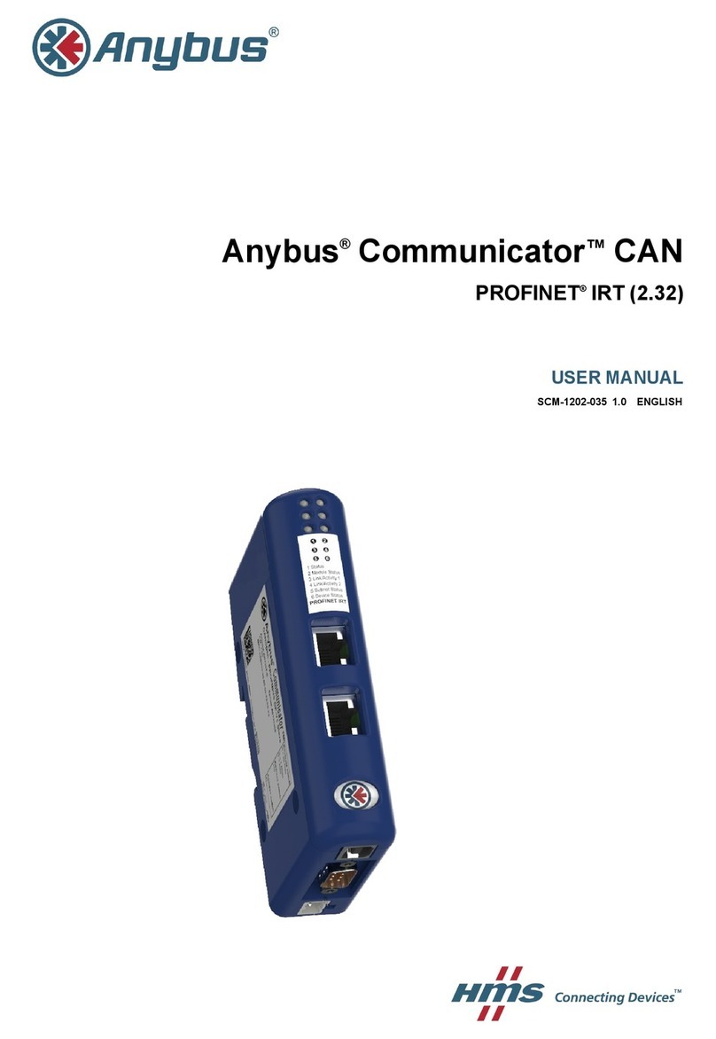
Anybus Communicator PROFINET IRT User manual

Anybus
®Communicator™
PROFINET®IRT (2.32)
USER MANUAL
SCM-1202-033-EN 1.1 ENGLISH

Important User Information
Liability
Every care has been taken in the preparation of this document. Please inform HMS Industrial Networks AB of any
inaccuracies or omissions. The data and illustrations found in this document are not binding. We, HMS Industrial
Networks AB, reserve the right to modify our products in line with our policy of continuous product development.
The information in this document is subject to change without notice and should not be considered as a commit-
ment by HMS Industrial Networks AB. HMS Industrial Networks AB assumes no responsibility for any errors that
may appear in this document.
There are many applications of this product. Those responsible for the use of this device must ensure that all the
necessary steps have been taken to verify that the applications meet all performance and safety requirements in-
cluding any applicable laws, regulations, codes, and standards.
HMS Industrial Networks AB will under no circumstances assume liability or responsibility for any problems that
may arise as a result from the use of undocumented features, timing, or functional side effects found outside the
documented scope of this product. The effects caused by any direct or indirect use of such aspects of the product
are undefined, and may include e.g. compatibility issues and stability issues.
The examples and illustrations in this document are included solely for illustrative purposes. Because of the many
variables and requirements associated with any particular implementation, HMS Industrial Networks AB cannot as-
sume responsibility for actual use based on these examples and illustrations.
Intellectual Property Rights
HMS Industrial Networks AB has intellectual property rights relating to technology embodied in the product de-
scribed in this document. These intellectual property rights may include patents and pending patent applications in
the USA and other countries.
Anybus®is a registered trademark of HMS Industrial Networks AB. All other trademarks mentioned in this document
are the property of their respective holders.
Anybus®Communicator™PROFINET®IRT (2.32) User Manual SCM-1202-033-EN 1.1

Anybus®Communicator™PROFINET®IRT (2.32) User Manual SCM-1202-033-EN 1.1
Table of Contents Page
1 Preface ............................................................................................................................... 3
1.1 About This Document.....................................................................................................3
1.2 Document history...........................................................................................................3
1.3 Document Conventions ..................................................................................................4
2 Description ....................................................................................................................... 5
2.1 Introduction ...................................................................................................................5
2.2 Basic Operation .............................................................................................................6
2.3 Data Exchange Model ....................................................................................................7
2.4 Subnetwork Protocol ......................................................................................................9
3 Installation ...................................................................................................................... 11
3.1 Installation Overview .................................................................................................... 11
3.2 Connectors and Indicators............................................................................................12
3.3 DIN Rail Mounting........................................................................................................12
3.4 Serial Subnetwork Interface..........................................................................................13
3.5 PROFINET Interface ....................................................................................................14
3.6 Power Connector .........................................................................................................14
3.7 PC Connector .............................................................................................................14
3.8 LED Indicators.............................................................................................................15
4 Network Configuration ................................................................................................ 17
4.1 General.......................................................................................................................17
4.2 Basic TCP/IP Concepts ................................................................................................18
4.3 TCP/IP Configuration ...................................................................................................19
4.4 Web Pages..................................................................................................................22
5 PROFINET Data Exchange.......................................................................................... 23
5.1 Overview.....................................................................................................................23
5.2 GSD File .....................................................................................................................23
5.3 Data Representation (IO Data and Record Data) ............................................................24

Anybus®Communicator™PROFINET®IRT (2.32) User Manual SCM-1202-033-EN 1.1
Table of Contents
6 Anybus Configuration Manager ................................................................................ 25
6.1 Main Window...............................................................................................................25
6.2 Basic Settings..............................................................................................................28
6.3 Nodes .........................................................................................................................32
6.4 Transactions (Master Mode and Generic Data Mode) .....................................................34
6.5 Frame Objects (Master Mode & Generic Data Mode) ......................................................39
6.6 Commands (Master Mode & Generic Data Mode)...........................................................46
6.7 Services (DF1 Master Mode) ........................................................................................50
6.8 Subnetwork Monitor .....................................................................................................54
6.9 Node Monitor...............................................................................................................55
6.10 Data Logger ................................................................................................................57
6.11 Configuration Wizard....................................................................................................58
6.12 Control and Status Registers ........................................................................................59
A Technical Data................................................................................................................ 63
A.1 General Specifications .................................................................................................63
A.2 Serial Interface ............................................................................................................63
A.3 PROFINET IRT Interface..............................................................................................63
B Regulatory Compliance............................................................................................... 64

Preface 3 (66)
1 Preface
1.1 About This Document
This document describes how to install and configure the Anybus Communicator PROFINET
IRT (2.32) gateway
For additional related documentation and file downloads, please visit www.anybus.com/support.
1.2 Document history
Version Date Description
1.0 2017-02-07 First release
1.1 2017-11-22 Updated for new firmware
Anybus®Communicator™PROFINET®IRT (2.32) User Manual SCM-1202-033-EN 1.1

Preface 4 (66)
1.3 Document Conventions
Ordered lists are used for instructions that must be carried out in sequence:
1. First do this
2. Then do this
Unordered (bulleted) lists are used for:
• Itemized information
• Instructions that can be carried out in any order
...and for action-result type instructions:
► This action...
➨leads to this result
Bold typeface indicates interactive parts such as connectors and switches on the hardware, or
menus and buttons in a graphical user interface.
Monospaced text is used to indicate program code and other
kinds of data input/output such as configuration scripts.
This is a cross-reference within this document: Document Conventions, p. 4
This is an external link (URL): www.hms-networks.com
This is additional information which may facilitate installation and/or operation.
This instruction must be followed to avoid a risk of reduced functionality and/or
damage to the equipment, or to avoid a network security risk.
Caution
This instruction must be followed to avoid a risk of personal injury.
WARNING
This instruction must be followed to avoid a risk of death or serious injury.
Anybus®Communicator™PROFINET®IRT (2.32) User Manual SCM-1202-033-EN 1.1

Description 5 (66)
2 Description
2.1 Introduction
Anybus Communicator PROFINET IRT (2.32) is intended for connecting non-networked indus-
trial devices and equipment to a PROFINET network. It performs an intelligent protocol conver-
sion and presents the serial data to the PROFINET IO Controller as easily processed I/O data.
The gateway is capable of converting almost any type of serial protocol such as Modbus RTU,
ASCII, DF1 or any other type of proprietary Query/Response or Produce/Consume protocol. It
can address up to 31 nodes on the serial subnetwork and supports the RS-232, RS-422 and
RS-485 physical standards.
Configuration
& Monitoring
Serial Communication DevicesSerial Communication Device
INVERTER
HMI
Multi-drop up to 31 Nodes
Multi-Node Serial SubnetworkSingle-Node Serial Subnetwork
Configuration
& Monitoring
PROFINET IO
Controller
PROFINET IO
Controller
INVERTER
HMI
ETHERNET
ETHERNET
PC / Web / SCADA
PC / Web / SCADA
Fig. 1 Network examples
Anybus
®Communicator™PROFINET®IRT (2.32) User Manual SCM-1202-033-EN 1.1

Description 6 (66)
2.2 Basic Operation
Anybus Communicator PROFINET IRT (2.32) is designed to exchange data between a serial
subnetwork and a higher level network. It does not have a fixed protocol for the subnetwork and
can be configured to handle almost any form of serial communication.
The gateway can issue serial telegrams cyclically, on change of state, or based on trigger
events issued by the control system of the higher level network. It can also monitor communica-
tion on the subnetwork and notify the higher level network when data has changed.
An essential part of the Anybus Communicator package is Anybus Configuration Manager, a
Windows-based application used to supply the gateway with a description of the subnetwork
protocol. The application has a easy to use graphical interface and does not require program-
ming skills.
Fig. 2 Anybus Configuration Manager
Anybus
®Communicator™PROFINET®IRT (2.32) User Manual SCM-1202-033-EN 1.1

Description 7 (66)
2.3 Data Exchange Model
2.3.1 Overview
The data exchanged on the subnetwork and the data exchanged on the higher level network re-
side in the same internal memory in the Anybus Communicator. In order to exchange data with
the subnetwork, the higher level network simply reads and writes data to memory locations that
have been specified in Anybus Configuration Manager. The same memory locations can then
be exchanged on the subnetwork.
Internal Memory
Input Data
(512 bytes)
Subnetwork
Output Data
(512 bytes)
General Data
Higher Level Network
Fig. 3 Memory buffer structure
The internal memory buffer is divided into three areas based on their function:
Input Data (512 bytes) This area can be read from by the higher level network.
Output Data (512 bytes) This area can be read from and written to by the higher level network.
General Data
(max. 1024 bytes)
This area cannot be accessed by the higher level network but can be used
for transfers between individual nodes on the subnetwork, or as a general
“scratch pad” for data.
The actual size of this area depends on the amount of data exchanged on
the subnetwork but can be a maximum of 1024 bytes.
2.3.2 Memory Map
When building the subnetwork configuration in Anybus Configuration Manager the areas in the
memory buffer will be mapped to the following memory locations:
Subnetwork:
Fieldbus:
E-mail Client:
SSI:
Subnetwork:
Fieldbus:
E-mail Client:
SSI:
Subnetwork:
Fieldbus:
E-mail Client:
SSI:
Read/Write
Read Only
Read Only
Read Only
Read Only
Read/Write
Read Only
Read/Write
Read/Write
-
-
-
Input Data Output Data General Data
0x000 0x200
0x1FF 0x3FF
0x400
0x???
Fig. 4 Memory Map
Anybus
®Communicator™PROFINET®IRT (2.32) User Manual SCM-1202-033-EN 1.1

Description 8 (66)
2.3.3 Data Exchange Example
In this example, a temperature regulator on the serial subnetwork exchanges data with a PLC
on the higher level network via the internal memory buffers in the Anybus Communicator.
The Temperature Regulator has two
registers, holding the Temperature Setpoint
and the Actual Temperature respectively.
The PLC exchanges data between its
internal memory and the slaves on the
PROFINET network
(the Anybus Communicator in this example)
The Communicator copies the Output
Register of the Temperature Regulator
to the Input Data area.
The Communicator copies the
Temperature Setpoint from the
Output Data area to the Input Register
in the Temperature Regulator.
The PLC Memory associated with
the Communicator is exchanged.
Data from the Input Data area is
copied to PLC Input Memory, and
PLC Output Memory is copied to
the Output Data area.
Input Data
Anybus Communicator
Serial Device - Temperature Regulator
PLC (PROFINET IO Controller)
Output Data General Data
0x000 0x200
0x1FF 0x3FF
0x400
0x???
Output Register Input Register
Temperature Setpoint
Actual Temperature
Actual Temperature
PLC Memory (Inputs) PLC Memory (Outputs)
Temperature Setpoint
Actual Temperature
(not used in this example)
PROFINETSubnetwork
Fig. 5 Example
Anybus
®Communicator™PROFINET®IRT (2.32) User Manual SCM-1202-033-EN 1.1

Description 9 (66)
2.4 Subnetwork Protocol
2.4.1 Protocol Modes
The Anybus Communicator features three distinct modes of operation regarding the subnet-
work communication: Master Mode,Generic Data Mode and DF1 Master Mode.
The protocol mode only specifies the basic communication model, not the actual subnetwork
protocol that is used.
Master Mode
In this mode, the Anybus Communicator acts as a master on the subnetwork and serial commu-
nication takes place in query-response fashion. The nodes on the network are not permitted to
issue messages until they are addressed by the gateway.
Broadcasts are an exception: Most protocols offer some way of sending messages simultane-
ously to all nodes on the network without expecting a response. This is also implemented in the
Anybus Communicator, which features a dedicated broadcaster node.
QUERY
RESPONSE
QUERY
RESPONSE
BROADCAST
Subnetwork
Node 1
Node 2
Anybus Communicator
Control System
Fig. 6 Master Mode
Anybus Configuration Manager comes preloaded with the most commonly used Modbus RTU
commands in Master Mode. Note however that this does not prevent other protocols based on
the same query-response message-scheme to be implemented.
Generic Data Mode
In this mode there is no master-slave relationship between the subnetwork nodes and the Any-
bus Communicator. Any node on the subnetwork, including the Anybus Communicator, may
spontaneously produce or consume messages. Nodes do not have to respond to messages or
wait for a query in order to send one.
The consumed data can be accessed from the higher level network, and/or vice versa.
PRODUCECONSUME
CONSUMEPRODUCE
PRODUCECONSUME
Subnetwork
Node 1
Node 2
Anybus Communicator
Control System
Fig. 7 Generic Data Mode
Anybus
®Communicator™PROFINET®IRT (2.32) User Manual SCM-1202-033-EN 1.1

Description 10 (66)
DF1 Master Mode
In this mode the Anybus Communicator act as a DF1 protocol master on the subnetwork. Serial
communication takes place in query-response fashion. The nodes on the network are not per-
mitted to issue messages until they are addressed by the gateway.
Communication in DF1 Master mode is based on services. A service represents a set of com-
mands and operations on the subnetwork that have been predefined in the Anybus Communi-
cator. Each service is associated with a set of parameters controlling how and when to use it on
the subnetwork.
QUERY
RESPONSE
QUERY
RESPONSE
Subnetwork
Node 1
Node 2
Anybus Communicator
Control System
Fig. 8 DF1 Master Mode
Anybus Configuration Manager comes preloaded with a number of services which can be se-
lected by the user. The actual DF1 commands that perform the services during runtime have
been predefined in the Anybus Communicator.
2.4.2 Protocol Building Blocks
The following building blocks are used in Anybus Configuration Manager to describe the sub-
network communication.
Node Anode represents a single device on the subnetwork. Each node can be
associated with a number of transactions.
Transaction Atransaction represents a complete serial telegram and consists of a number of
frame objects. Each transaction is associated with a set of parameters controlling
how and when to use it on the subnetwork.
Commands Acommand is a predefined transaction which is stored in a list in Anybus
Configuration Manager. This simplifies common operations by allowing
transactions to be stored and reused.
Frame Object Aframe object is a low level entity that is used to compose a transaction. A frame
object can represent a fixed value (a constant), a range of values (limit objects), a
block of data, or a calculated checksum.
See Anybus Configuration Manager, p. 25 on how to use protocol building blocks.
Anybus®Communicator™PROFINET®IRT (2.32) User Manual SCM-1202-033-EN 1.1

Installation 11 (66)
3 Installation
This product contains parts that can be damaged by electrostatic discharge (ESD).
Use ESD prevention measures to avoid damage.
3.1 Installation Overview
These are the basic steps for installing Anybus Communicator gateways.
Depending on the fieldbus network type there may also be configuration switches, etc. on the
Anybus Communicator that need setting. See the following sections in this document for more
information.
Basic installation steps
1. Mount the Anybus Communicator on the DIN rail.
2. Connect the serial and fieldbus network interfaces.
3. Configure the fieldbus network interface hardware (if applicable).
4. Connect the configuration cable between the gateway and a PC.
5. Connect the power cable and apply power.
6. Download Anybus Configuration Manager from www.anybus.com/support
and install it on the PC following the instructions in the installer.
(Anybus Configuration Manager requires Microsoft®Windows XP or later)
7. Continue to Network Configuration, p. 17
Anybus®Communicator™PROFINET®IRT (2.32) User Manual SCM-1202-033-EN 1.1

Installation 12 (66)
3.2 Connectors and Indicators
ALED indicators
BPROFINET IRT network interface
CPC connector
DSerial subnetwork interface
EPower connector
FDIN rail mount
3.3 DIN Rail Mounting
The unit must be electrically grounded through the DIN rail for EMC compliance.
Mount on DIN rail
1
2
Fig. 9 Push down to mount or remove
1. Hook the unit onto the upper lip of
the rail and push gently downwards.
2. Push the unit towards the rail until it
snaps into place.
Remove from DIN rail
1. Push the unit gently downwards on the rail.
2. Pull the bottom end of the unit free of the rail and remove it.
A
B
C
D
E
F
Anybus®Communicator™PROFINET®IRT (2.32) User Manual SCM-1202-033-EN 1.1

Installation 13 (66)
3.4 Serial Subnetwork Interface
Serial Connector
The serial subnetwork is connected via a 9-pin female D-sub connector. The allocation of sig-
nals to the different pins in the connector depends on which physical communication interface
is used (RS-232, RS-422 or RS-485).
9 6
15 (female)
Fig. 10 D-sub connector (DE-9F)
Pin Description RS-232 RS-422 RS-485
1 +5 V Output (100 mA max.) xxx
2 RS-232 Rx x
3 RS-232 Tx x
4 (reserved)
5Signal Ground xxx
6 RS-422 Rx + x
7RS-422 Rx - x
8 RS-485 + / RS-422 Tx + x x
9 RS-485 - / RS-422 Tx - x x
Housing Shield xxx
Do not connect Signal Ground (pin 5) to Protective Earth (PE) of other nodes on
the subnetwork, as this may damage the on-board serial transceivers. Only
connect it to the Signal Ground of the other nodes (if available).
Bias Resistors (RS-485 only)
When idle, RS-485 enters an indeterminate state, which may cause the serial receivers to pick
up noise from the serial lines and interpret this as data. To prevent this, the serial lines should
be forced into a known state using bias resistors.
The bias resistors form a voltage divider, forcing the voltage between the differential pair to be
higher than the threshold for the serial receivers, typically >200 mV.
Bias resistors should only be installed on one node. Installing bias resistors on several nodes
may compromise the signal quality on the network and cause transmission problems.
Termination (RS-485 and RS-422 only)
To avoid reflections on the serial lines, it is important to properly terminate the subnetwork by
placing termination resistors between the serial receivers near the end nodes.
The resistor value should ideally match the characteristic impedance of the cable, typically
100–120 Ω.
Anybus®Communicator™PROFINET®IRT (2.32) User Manual SCM-1202-033-EN 1.1

Installation 14 (66)
3.5 PROFINET Interface
The PROFINET IRT interface contains a dual port Ethernet switch with RJ45 type connectors.
The two ports are labeled LAN 1 and LAN 2.
1 8
Fig. 11 Ethernet connector (RJ45)
Pin Function
1 TD+
2 TD-
3 RD+
6 RD-
4, 5, 7, 8 (reserved)
3.6 Power Connector
See also Technical Data, p. 63 regarding power supply requirements.
1 2
Fig. 12 Power connector
Pin Signal
1 +24 VDC
2 Power Ground
3.7 PC Connector
Used for connecting to a computer using the included configuration cable.
1 4
Fig. 13 PC Connector (RJ11)
Pin Signal
1 Signal ground
2 Signal ground
3 RS-232 Rx (input)
4 RS-232 Tx (output)
The RJ11 type 4P4C modular connector can also be referred to as RJ9.
1
2
3
4
1
2
3
4
5
6
7
8
9
DE-9 (PC)RJ11 (Communicator)
GND
GND
Rx
Tx
RS-232 Tx
RS-232 Rx
GND
Fig. 14 Configuration cable
Anybus
®Communicator™PROFINET®IRT (2.32) User Manual SCM-1202-033-EN 1.1

Installation 15 (66)
3.8 LED Indicators
The LED indicators provide model-specific diagnostic information about the communication and
status of the network interfaces as well as general device status.
1 2
3
5
4
6
LED 1 to 4 Model-specific information
LED 5 Serial subnetwork status
LED 6 Device status
LED Indication Meaning
1 - Network Status Off Offline
– No power
– No connection to IO Controller
Green Online (RUN)
– Connection to IO Controller
Green, 1 flash Online (STOP)
– Connection to IO Controller
– IO Controller in STOP state or IO data bad
– RT synchronization not finished
Red Fatal error
Red, 1 flash Station name error
Red, 2 flashes IP address error
Red, 3 flashes Configuration error
Alternating red/green Firmware update in progress
2 - Module Status Off No power or initializing
Green Normal operation
Green, 1 flash Diagnostic event present
Red Fatal error
Alternating red/green Firmware update in progress
3 - Link/Activity 1
4 - Link/Activity 2
Off No power or no link detected
Green Link OK
Green, flickering Transmitting/receiving data
LED Indication Meaning
5 - Subnet Status Off No power
Green Running
Green, flashing Running, one or more transaction errors
Red Transaction error/timeout, or subnet stopped
6 - Device Status Off No power
Green Initializing
Green, flashing Running
Red Bootloader mode
Alternating red/green Configuration error
Anybus
®Communicator™PROFINET®IRT (2.32) User Manual SCM-1202-033-EN 1.1

Installation 16 (66)
LED Indicator Timing Intervals
On
Off
50 ms
50 ms
Flickering
LED
On
Off
Blinking
LED 200 ms 200 ms
On
Off
Single flash
LED 200 ms 1000 ms
On
Off
Double flash
LED 200 ms 1000 ms
200 ms 200 ms
On
Off
Quadruple flash
LED 200 ms 1000 ms
200 ms 200 ms
200 ms 200 ms 200 ms 200 ms
On
Off
Triple flash
LED 200 ms 1000 ms
200 ms 200 ms
200 ms 200 ms
Fig. 15 LED indicator timing intervals
Anybus
®Communicator™PROFINET®IRT (2.32) User Manual SCM-1202-033-EN 1.1

Network Configuration 17 (66)
4 Network Configuration
4.1 General
To be able to communicate over Ethernet the PROFINET IRT interface needs a valid TCP/IP
network configuration. This section explains the basic concepts of TCP/IP networking and de-
scribes how to configure the TCP/IP settings for the interface.
TCP/IP Settings
The TCP/IP settings are usually configured from the PROFINET IO Controller but can also be
set locally using the IPconfig tool. See TCP/IP Configuration, p. 19.
When Ethernet communication has been established, the TCP/IP settings can also be changed
from the web interface. See Web Pages, p. 22.
DHCP and BootP
The TCP/IP settings can be set automatically from a DHCP or BootP server. If no DHCP server
is found, the module will fall back on its current settings. If no current settings are available the
module will halt and the status LED will indicate a network configuration error. The network con-
figuration may still be accessed using IPconfig.
DCP (Discovery and Control Protocol)
Anybus Communicator PROFINET IRT (2.32) supports DCP, which allows a PROFINET IO
Controller or Supervisor to change the network settings during runtime. The settings applied
through DCP will replace the currently stored settings.
Anybus®Communicator™PROFINET®IRT (2.32) User Manual SCM-1202-033-EN 1.1

Network Configuration 18 (66)
4.2 Basic TCP/IP Concepts
IP Address
The IP address is used to identify each node on a TCP/IP network. IP addresses are written as
four decimal integers (0–255) separated by dots, where each integer represents the binary val-
ue of one byte of the IP address. This is known as dot-decimal notation.
Example: 10000000 00001010 00000010 00011110 is written as 128.10.2.30
The following IP addresses are reserved for special purposes and cannot be used:
0.n.n.n First byte zero — used for broadcast messages
127.n.n.n First byte 127 — used for loopback addresses to the local host
n.n.n.0 Last byte zero — identifies a whole network/subnet
n.n.n.255 Last byte 255 — used for broadcast messages
Subnet Mask
The IP address is divided into three parts: Net ID,Subnet ID and Host ID. A subnet mask is a
32-bit binary pattern, where a set bit allocates a bit for Network/Subnet ID, and a cleared bit al-
locates a bit for the Host ID. The subnet mask is usually written in dot-decimal notation.
Example: To make the IP address 128.10.2.30 belong to subnet 128.10.2, the subnet
mask must be 255.255.255.0.
Subnet mask: 11111111 11111111 11111111 00000000 (255.255.255.0)
Net ID / Subnet ID
Host ID
Default Gateway
For devices to be able to communicate over Ethernet they must either belong to the same sub-
net or communicate via a gateway or router.
A gateway or router routes communication between networks, i.e. it enables the nodes on one
network to access the nodes on another. The default gateway address in the TCP/IP settings of
your product specifies the IP address of the gateway or router on the local network.
Anybus®Communicator™PROFINET®IRT (2.32) User Manual SCM-1202-033-EN 1.1
Table of contents
Other Anybus Gateway manuals

Anybus
Anybus X-gateway Assembly instructions

Anybus
Anybus AB7702 User manual

Anybus
Anybus Communicator Modbus plus User manual

Anybus
Anybus X-gateway User manual

Anybus
Anybus Communicator CAN PROFINET IRT 2.32 User manual

Anybus
Anybus PROFINET IRT 2.32 User manual

Anybus
Anybus RS-232 User manual

Anybus
Anybus Modbus to BACnet Gateway User manual