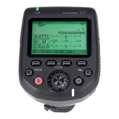
AODELAN E4 User manual

Wireless Flash Trigger
E4
User Manual
Shenzhen Aodelan Technology Co., Ltd.
Printed in China

Thank you for purchasing an AODELAN product.
AODELAN E4 is a TTL transmitter compatible with AODELAN radio system. It can be used to wirelessly
synchronize the AODELAN flashes with the camera, combining TTL (Through-The-Lens) exposure control
mode with the option to manually adjust the exposure brightness.
Please read this user manual as well as the user manual provided with your camera and flash which
works with E4 before use.
For your safety
Before using your product, please read the following safety precaution carefully to ensure correct and safe
use.
Do not disassemble or attempt to repair it.
Do not use the product in the presence of flammable or explosive gas.
The product is not waterproof. Please keep away from rain, snow and high humidity conditions.
Do not expose the product to high temperature over 45℃ (e.g. left in a car trunk).
Do not clean the product with organic solvent or alcohol-based liquid.
A thorough explanation of how to use the product by an adult is required when the product is used by
children. Supervise children while they are using the product.
Consult local authorities on the proper disposal or recycling of a battery.

RED 2014/53/EU
Declaration of Conformity EC
Hereby, Shenzhen Aodelan Technology Co., Ltd. declares that this product is in compliance with essential
requirements and other relevant provisions of Directive 2014/53/EU. This product can be used across EU
member states. A copy of the Declaration of Conformity can be found at www.aodelan.net.
Declaration of Conformity USA AND CANADA
Product name: Wireless Flash Trigger
Trade name: AODELAN
Model number: E4
FCC ID: 2AEJW-E4
IC ID: 25192-E4
Manufacturer: Shenzhen Aodelan Technology Co., Ltd.
FCC Statement
This equipment has been tested and found to comply with the limits for a Class B digital device, pursuant to part
15 of the FCC Rules. These limits are designed to provide reasonable protection against harmful interference in
a residential installation. This equipment generates, uses and can radiate radio frequency energy and, if not
installed and used in accordance with the instructions, may cause harmful interference to radio communications.
However, there is no guarantee that interference will not occur in a particular installation. If this equipment does
cause harmful interference to radio or television reception, which can be determined by turning the equipment
off and on, the user is encouraged to try to correct the interference by one or more of the following measures:
Reorient or relocate the receiving antenna.
Increase the separation between the equipment and receiver.
Connect the equipment into an outlet on a circuit different from that to which the receiver is connected.
Consult the dealer or an experienced radio/TV technician for help.
Caution: Any changes or modifications to this device not explicitly approved by manufacturer could
void your authority to operate this equipment.
This device complies with part 15 of the FCC Rules. Operation is subject to the following two conditions: (1) This
device may not cause harmful interference, and (2) this device must accept any interference received, including
interference that may cause undesired operation.
RF Exposure Information
The device has been evaluated to meet general RF exposure requirement. The device can be used in portable
exposure condition without restriction.
CAUTION
RISK OF EXPLOSION IF BATTERY IS REPLACED BY AN INCORRECT TYPE. DISPOSE OF USED

BATTERIES ACCORDING TO THE INSTRUCTIONS.
ISED Statement
This device complies with Industry Canada license‐exempt RSS standard(s).Operation is subject to the
following two conditions: (1) This device may not cause interference, and (2) This device must accept any
interference, including interference that may cause undesired operation of the device.
The digital apparatus complies with Canadian CAN ICES‐3 (B)/NMB‐3(B).
Le présentappareilestconforme aux CNR d'Industrie Canada applicables aux appareils
radio exempts de licence. L'exploitationestautorisée aux deux conditions suivantes: (1) l'appareil ne doit pas pr
oduire de brouillage, et (2) l'utilisateur de l'appareildoit accepter tout brouillageradioélectriquesubi, mêmesi le br
ouillageest susceptible d'encompromettre le fonctionnement.
This radio transmitter (ISED certification number: 12258A-ST8) has been approved by Industry Canada to
operate with the antenna types listed with the maximum permissible gain indicated. Antenna types not included
in this list, having a gain greater than the maximum gain indicated for that type, are strictly prohibited for use with
this device.
Le présent émetteur radio (ISED certification number: 12258A-ST8) a été approuvé par Industrie Canada pour
fonctionner avec les types d'antenne énumérés ci-dessous et ayant un gain admissible maximal. Les types
d'antenne non inclus dans cette liste, et dont le gain est supérieur au gain maximal indiqué, sont strictement
interdits pour l'exploitation de l'émetteur.
Radiation Exposure Statement
This equipment complies with Canada radiation exposure limits set forth for an uncontrolled environment. This
equipment should be installed and operated with minimum distance 20cm between the radiator & your body.
Déclaration d'exposition aux radiations
Cet équipement est conforme Canada limites d'exposition aux radiations dans un environnement non contrôlé.
Cet équipement doit être installé et utilisé à distance minimum de 20cm entre le radiateur et votre corps.
This device is intended only for OEM integrators under the following condition:
The transmitter module may not be co-located with any other transmitter or antenna.
As long as the condition above is met, further transmitter test will not be required. However, the OEM integrator
is still responsible for testing their end-product for any additional compliance requirements required with this
module installed.
Cet appareil est conçu uniquement pour les intégrateurs OEM dans les conditions suivantes:
Le module émetteur peut ne pas être coïmplanté avec un autre émetteur ou antenne.
Tant que les 1 condition ci-dessus sont remplies, des essais supplémentaires sur l'émetteur ne seront pas
nécessaires. Toutefois, l'intégrateur OEM est toujours responsable des essais sur son produit final pour toutes
exigences de conformité supplémentaires requis pour ce module installé.
Important Note:
In the event that these conditions cannot be met (for example certain laptop configurations or co-location with
another transmitter), then the Canada authorization is no longer considered valid and the IC cannot be used on
the final product. In these circumstances, the OEM integrator will be responsible for re-evaluating the end
product (including the transmitter) and obtaining a separate Canada authorization.

Note Importante:
Dans le cas où ces conditions ne peuvent être satisfaites (par exemple pour certaines configurations
d'ordinateur portable ou de certaines co-localisation avec un autre émetteur), l'autorisation du Canada n'est plus
considéré comme valide et l' IC ne peut pas être utilisé sur le produit final. Dans ces circonstances, l'intégrateur
OEM sera chargé de réévaluer le produit final (y compris l'émetteur) et l'obtention d'une autorisation distincte au
Canada.
End Product Labeling
The final end product must be labeled in a visible area with the following: Contains IC: 25192-E4.
Plaque signalétique du produit final
Le produit final doit être étiqueté dans un endroit visible avec l'inscription suivante: Contient des IC: 25192-E4.
Manual Information to the End User
The OEM integrator has to be aware not to provide information to the end user regarding how to install or
remove this RF module in the user’s manual of the end product which integrates this module.
The end user manual shall include all required regulatory information/warning as show in this manual.
Manuel d'information à l'utilisateur final
L'intégrateur OEM doit être conscient de ne pas fournir des informations à l'utilisateur final quant à la façon
d'installer ou de supprimer ce module RF dans le manuel de l'utilisateur du produit final qui intègre ce module.
Le manuel de l'utilisateur final doit inclure toutes les informations réglementaires requises et avertissements
comme indiqué dans ce manuel.

I. Parts
1. Display
2. Mode Button
3. Energy Adjustment Buttons
(<+> Increase, <-> Decrease)
4. Group Buttons (A, B, C)
5. Test Button
6. Sync Button
7. Head Button
8. Channel Button
9. Model Button
10. Indicator
11. Power Button
12. USB Port
13. Mounting Foot Lock Lever
14. Battery Compartment
15. Hot Shoe Mounting Foot
Display
1
2
3
4
5
6
7
8
9
10
11
Grou
p
Energy Modeling Light Status
Battery Level
Mode
Sync
Channel
15
13
14
12

II. Getting Started
Installing the batteries
1. Open the battery compartment cover from the back of E4.
2. Install 2 AAA batteries in accordance with the illustrated direction inside the battery compartment.
3. Close the battery compartment cover in place.
Precautions for Use
The battery level is shown in the upper right corner of the Display [1].
When the battery is low, or will be shown in the Display [1], replace the batteries with new ones.
Turning E4 on/off
1. Turn on: Press the Power Button [11] to turn on the E4, the Display [1] lights up and contents are displayed.
2. Turn off: Press and hold the Power Button [11] until the Display [1] lights off.
Connecting to the camera
1. Turn off the camera and E4.
2. Slide the Hot Shoe Mounting Foot [15] of the E4 into the camera’s hot shoe mount.
3. Lock the E4 by sliding the Mounting Foot Lock Lever [13] to right until the lock lever clicks in place.
4. Turn on the camera and E4 and set the shooting mode of the camera to Manual (recommended).
5. To detach E4, press the lock-release button on the Mounting Foot Lock Lever [13] while slide the lock lever
all the way back to the left, then slide the E4 out of camera’s hot shoe mount.

III. Basic Functions and Buttons
Channel Selection
1. Chanel selection is used to select one of eight specific frequencies in the 2.4GHz band.
2. Press the Channel Button [8] to select the channel.
The currently selected channel is shown in the CHANNEL section on the Display [1].
Group Selection
1. Groups are used to allow remote radio control of selected flashes.
2. All flashes that are assigned to the same group under the same channel will be controlled by E4
simultaneously.
3. Press the Group Button [4] A / B or C to select the group.
The selected Group is shown with its letter in a box.
4. Press the Group Button [4] corresponding to the currently selected group again to select all groups.
If there is no group letter is shown with a box, all groups are selected
Mode Selection (TTL or Manual)
1. The currently selected mode is shown in the MODE section on the Display [1].
2. Press the Mode Button [2] to toggle between TTL (Through the lens, Automatic) and M (Manual) mode.
TTL mode: The camera dictates the light output of the flashes. The relationship between the energy
levels for group A, B and C can be adjusted.*
M mode: The light output for group A, B and C can be controlled manually.
*Please refer to the instruction of relative energy level in the section of “Operation in TTL mode” in this user
manual
Sync selection (1st curtain, 2nd curtain and HSS)
1. The selected sync setting (camera’s sync setting) is shown in the SYNC section on the Display [1].
2. Press the Sync Button [6] to cycle through the sync options:
1st: First-curtain synchronization. The flashes fire immediately after the exposure starts.
2nd: Second- curtain synchronization. The flashes fire right before the shutter closes.
HSS: High speed synchronization. HSS mode is selected.
Precautions for Use
The sync setting can also be selected in the camera menu. Refer to the camera’s user manual.
HSS (High speed synchronization)
1. HSS enables shooting with flash at a faster shutter speed than the fastest external flash sync speed (x-sync)
of the camera, all the way down to 1/8000s (may differ between camera models).
2. This option can be extremely useful to limit the influence of ambient light when shooting in bright conditions.
Precautions for Use
During a HSS flash, the flashes are pulsing to provide a constant light output during the time when the
shutter is open.
To ensure a perfect exposure and a stable flash pulse, the flash uses only the upper part of its power range
when in HSS Mode. Exact range may differ between flash models.
Frequent use of HSS will have an impact on the life-time of the flash tube.

Remote Control – Head Control; Model Control; Energy Adjustment
1. E4 can remotely radio control all flashes with built-in AODELAN radio system functionality.
2. The Channel settings on the E4 unit must match the Channel settings of the flashes.
3. Press the Head Button [7] to turn on/off the heads in the selected group.
If the heads in a group are turned off, "--" will be shown after the group letter.
4. Press the Model Button [9] to turn on/off the modeling light in the selected group.
If the modeling light in a group is turned on, “ ” will be shown in the MODEL column after the group
letter.
5. Press the Energy Adjustment Buttons [3] to adjust the energy level for the group in relation to the other
groups (TTL mode) or the energy level for the group (M mode). **
<+> represents increase.
<-> represents decrease.
Short press Energy Adjustment Button (< 2 seconds) to adjust the flash output energy level in 1/10
f-stop increments.
Long press Energy Adjustment Button (> 2 seconds) to adjust the flash output energy level in 1 f-stop
increments.
**Since energy adjustments work differently in TTL mode and Manual mode, we recommend to carefully read
the detailed instructions for both modes in the section of “Operating Instructions” in this user manual.
Command Confirmation (only in M mode)
1. If the output energy of a flash has been set to maximum or minimum level, then the flash cannot continue to
increase or decrease its output energy as commanded by the E4.
2. At the point E4 will make continuous and short beeps to signal that the command was not executed.
3. The energy of all flashes in the group will remain unchanged.
Test Function
1. Press the Test Button [5] to manually transmit a sync signal for remote flash triggering to verify expected
functionality.
Beep
1. Press and hold the Channel Button [8] until the E4 makes two short beeps to turn on or off the E4 button
beep.
2. There will be a long beep when E4 is turned on regardless of whether the beeper is turned on or not.
3. Some functions are not supported in certain situations; there will be no beep when the corresponding button
is pressed even if the beeper is turned on. For example, selecting a group and turning off its head, then
there will be no beep when the Energy Adjustment Buttons [3] or Model Button [9] is pressed.
Auto Power Off
1. E4 automatically turns off after 30 minutes of inactivity.
2. Each time after the E4 is turned on by pressing the Power Button [11], the auto power off function will be
enabled.
3. To deactivate the auto power off function, press and hold the Energy Adjustment Button [3] “+” while the E4
is off, then press and hold the Power Button [11] at the same time. Deactivation is confirmed by two short
beeps.

Factory Settings
1. Ensure that the E4 is turned off.
2. To reset the E4 to factory settings, press and hold down the Mode Button [2] and then press and hold the
Power Button [11] simultaneously until the Display [1] shows “rES”.
3. Release the buttons, E4 is turned on and reset to factory settings.
4. The factory settings of E4 are - TTL mode, 1st (First-curtain synchronization), Channel 1, all groups, the
relationship between the energy levels for group A, B and C is all 0.0.
Other functions
1. Power Saving
To save battery, the backlight of Display [1] will automatically turn off after 30 seconds of inactivity.
Press the Power Button [11] to turn on the display backlight
The display backlight also switches on when any of the function buttons are used..
2. Relay State
Press and hold the Mode Button [2] until E4 makes two short beeps to enter into the Relay State or to
exit and return to the Standard State.
The Indicator [10] blinks red in Relay State.
The Indicator [10] blinks green in Standard State.
The E4 in replay state only works with the E2 in reply state receive mode. ***
***Refer to the user manual of E2 for more info.
3. Firmware Update
We recommend that you look for firmware updates before you start using your new E4.
Press and hold the Mode Button [2] for 10 seconds when the E4 is turned on, the current firmware
version number is shown on the Display [1].
Go to www.aodelan.net to download the latest firmware update package for the corresponding E4
version, update your E4 to the latest firmware version according to the provided Update Instruction.

IV. Operating Instructions
Precautions for Use
Before starting all of the following operations please turn off E4 as well as the camera and flashes which
work with E4, and turn on all units after the connection is completed.
The following operations are all based on E4 is in standard state, the Indicator [10] blinks green.
1. Connect the E4 to the camera.
2. Set the flashes to synchronization via radio.
3. Set the E4 and the flashes to the same radio channel.
4. Select the same group settings (A/B or C) for all flash heads that shall be controlled simultaneously.
5. Press the Test Button [5] on the E4 to verify that the flash heads fire as expected.
6. Press the Mode Button [2] to toggle between TTL (Through the lens, Automatic) and M (Manual) mode.

Operation in TTL mode (Through the lens, Automatic mode)
In TTL mode the camera dictates the light output of the flashes. If more than one light group is used the
relationships between the energy levels for group A, B and C can be adjusted. This can, for example, be used to
achieve more light on one side of the object.
1. Press the A, B or C Group Button [4] to select the group you want to adjust.
2. Use the Energy Buttons [3] to set the relative light output for the selected group, in relation to the other
groups. The relations can be set ±2.0 f-stop for each group A, B or C. Relations should not be confused with
exposure compensation. (Carefully read “Precautions for use” in the end of this section.)
3. Press the Model Button [9] to turn on/off the modeling light in the selected group(s).
4. Press the Head Button [9] to turn on/off the heads in the selected group(s) (if the heads in a group are
turned off, the relation value for that group will display ‘--’).
5. When changing from M mode to TTL mode, the previous TTL relation values are displayed.
Example of E4 Display[1] settings in TTL mode operation
The corresponding settings of the display shown in the figure are:
- TTL mode, First-curtain synchronization (1st).
- Channel 1, Group A is selected to be adjusted.
- The relative light output from flashes in group B is set to 3.2 f-stops more than flashes in group A. (A to -1.5
f-stops and B to +2.0 f-stops).
- Flashes in Group C are turned off.
- The modeling light is turned on in both group A and B.
Precautions for use
Relation values should not be mistaken for flash exposure compensation. To compensate the total flash
exposure, always use the flash exposure compensation function in the camera. Refer to camera user
manual for details.
If flashes without AODELAN TTL support are used in combination with AODELAN flashes in TTL mode, the
flash outputs of the non-TTL flashes are added to the total flash exposure. Such flashes can, for example,
be used to manually set the exposure on the background.
If an Aodelan-raido-system compatible flash is set to group D, E or F under the same channel, it will be
synchronized but not be part of the TTL calculation. The flash outputs of these flashes are added to the total
flash exposure and can for instance be used to manually set the exposure on the background.

Operation in M mode (Manual mode)
With the E4 set to M mode, the light output for groups A, B and C can be adjusted manually. By alternating
between TTL and M mode, you can test your way to the perfect light.
1. Press the A, B or C Group Button [4] to select the corresponding group, or to select all groups.
2. Use the Energy Buttons [3] to adjust the light output for the group. The adjustment (increase/decrease)
always starts from the current light output setting on the flashes and the adjustment value is momentarily
(approx. 3 seconds) shown in the ENERGY section on the Display [1].
3. Press the Model Button [9] to turn on/off the modeling light in the selected group(s).
4. Press the Head Button [7] to turn on/off the heads in the selected group(s) (if the heads in a group are
turned off, the light output energy value for that group will display “--”)。
Example of E4 Display[1] settings in M mode operation
The corresponding settings of the display shown in the figure are:
- M mode, First-curtain synchronization (1st).
- Channel 1, Group B is selected to be adjusted.
- Flashes in Group C are turned off.
- If the light output for group A or B is adjusted, the energy change will be shown momentarily in the ENERGY
section on the Display [1].
- The modeling light is turned on in group A.
Precautions for use
The current energy adjustment value is only shown on the Display [1] momentarily and will disappear after
about 3 seconds.
When you adjust the energy again, the initial value starts again from +/- 0.1 (short press the Energy
Adjustment Button [3]) or from +/- 1.0 (long press the Energy Adjustment Button [3]).
When all groups are selected E4 will also control the flashes in group D, E or F (selected on flash).

V. Specifications
Indicator [10]
State and operation on E4 Indicator
Standby in standard state Blinks in green
Standby in relay state Blinks in red
Communicating with the camera Keeps on in green
Sent a flash synchronization command Lights up in red for approx. 0.3 seconds
Notes
“Blinks” means blinks once per second.
Frequency: 2.4 GHz
Range: Up to 200m (656ft) for normal triggering
Up to 100m (330ft) for remote control and TTL
No. of channels: 8 channels (1-8)
No. of groups per channel: 3 groups (A/B and C)
Power: 2 x AAA batteries
Operation modes: TTL (Through the lens, Automatic), M (Manual)
Camera TTL compatibility: Canon E-TTL II
Synchronization mode: First-curtain synchronization (1st),
Second- curtain synchronization (2nd),
High speed synchronization (HSS)
Max. Sync speed: 1st or 2nd sync: 1/250s
HSS: 1/8000s
(The speed may differ between camera models)
Antenna: Internal antenna
Interface: Multi contacts hot shoe mounting foot x 1
Micro-USB B port x 1
Accessory: Strap x 1
Dimensions: Approx. 91 x 57 x 37mm (3.6 x 2.2 x 1.2 in)
Weight: Approx. 80g (2.8 oz) (without batteries)
Specifications and design are subject to change without notice.

FCC Warning
This device complies with part 15 of the FCC rules. Operation is subject to the following two
conditions: (1) this device may not cause harmful interference, and (2) this device must accept
any inte rference received, including interference that may cause undesired operation.
Changes or modifications not expressly approved by the party responsible for compliance could
void the user's authority to operate the equipment.
NOTE: This equipment has been tested and found to comply with the limits for a Class B digital
device, pursuant to part 15 of the FCC Rules. These limits are designed to provide reasonable
protection against harmful interference in a residential installation. This equipment generates
uses and can radiate radio frequency energy and, if not installed and used in accordance with the
instructions, may cause harmful interference to radio communications. However, there is no
guarantee that interference will not occur in a particular installation. If this equipment does
cause harmful interferenceto radio or television reception, which can be determined by turning
the equipment off and on, the user is encouraged to try to correct the interference by one or
more of the following measures:
•Reorient or relocate the receiving antenna.
•Increase the separation between the equipment and receiver.
•Connect the equipment into an outlet on a circuit different from that to which the receiver is
connected.
•Consult the dealer or an experienced radio/TV technician for help.
Radiation Exposure Statement
This equipment complies with FCC radiation exposure limits set forth for an uncontrolled
environment. This equipment should be installed and operated with minimum distance 20cm
between the radiator and your body.
Radiation Exposure Statement
To maintain compliance with the FCC's RF exposure guidelines,place the product at least 20cm from
nearby persons.

ISED Statement
‐English: This device complies with Industry Canada license‐exempt RSS standard(s).
Operation is subject to the following two conditions: (1) This device may not cause interference,
and (2) This device must accept any interference, including interference that may cause
undesired operation of the device. The digital apparatus complies with Canadian CAN ICES‐3
(B)/NMB‐3(B).
‐French: Le présentappareilestconforme aux CNR d'Industrie Canada applicables aux appareils
radio exempts de licence. L'exploitationestautorisée aux deux conditions suivantes: (1) l'appareil
ne doit pas produire de brouillage, et (2) l'utilisateur de l'appareildoit accepter tout
brouillageradioélec triquesubi, mêmesi le brouillageest susceptible d'encompromettre le
fonctionnement.
Table of contents
Other AODELAN Transmitter manuals
Popular Transmitter manuals by other brands

Comet System
Comet System T0210 instruction manual

InFocus
InFocus SimpleShare INA-SIMTTM1 user guide

Thies CLIMA
Thies CLIMA 4.3515.30.000 Instructions for use

RKI Instruments
RKI Instruments 65-2646RKS-SW Operator's manual

Niles
Niles SW-R installation guide

Setra Systems
Setra Systems C290 operating instructions

PCB Piezotronics
PCB Piezotronics IMI SENSORS 682C03 Installation and operating manual

Johnson
Johnson VIKING 6N2 Assembly and operating instructions

AMP
AMP VT15 Series Operation manual

Extron electronics
Extron electronics DTP T HWP D Series user guide

YOKOGAWA
YOKOGAWA DPharp Series user manual

WebGate
WebGate WebEye A10 user guide