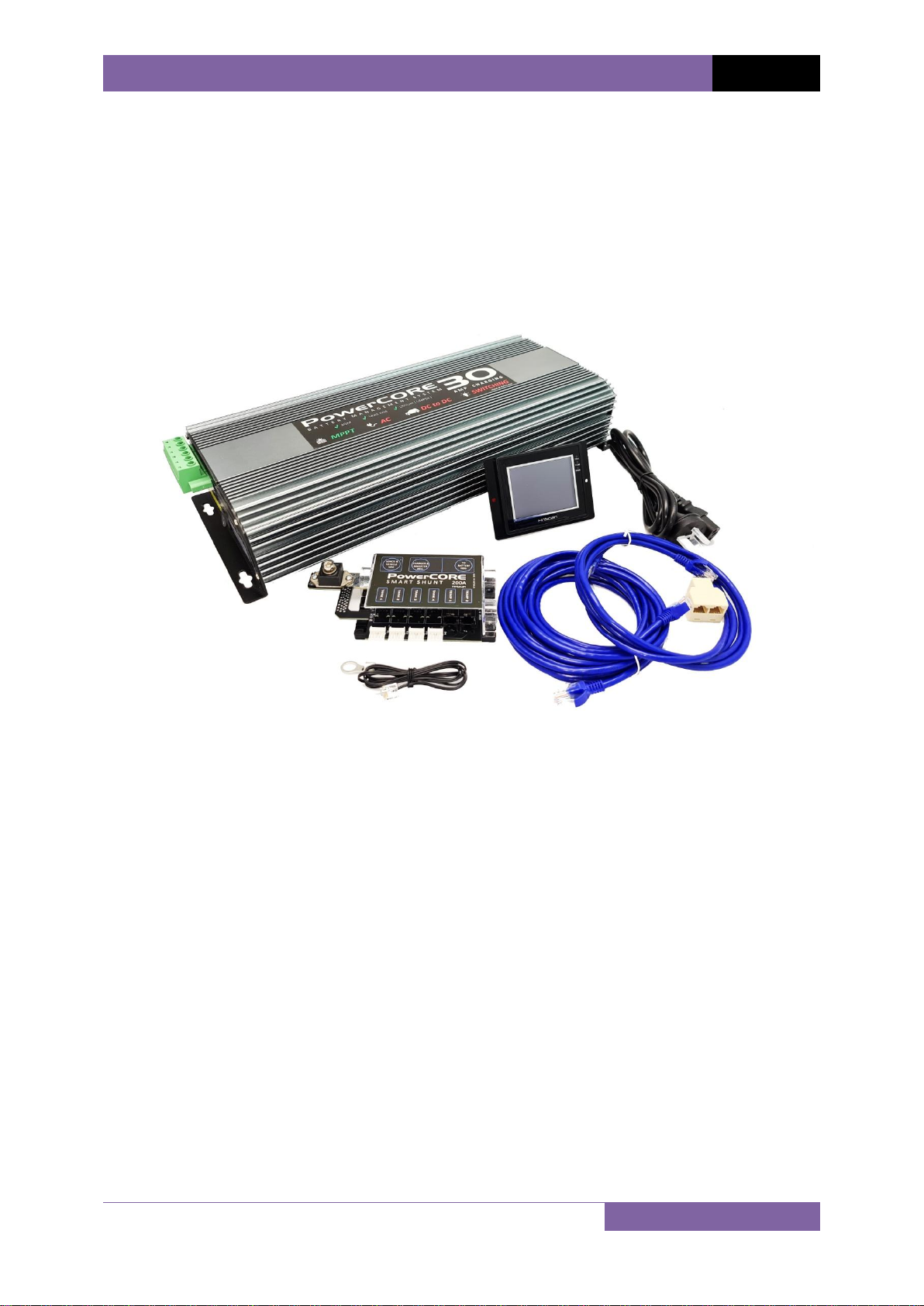
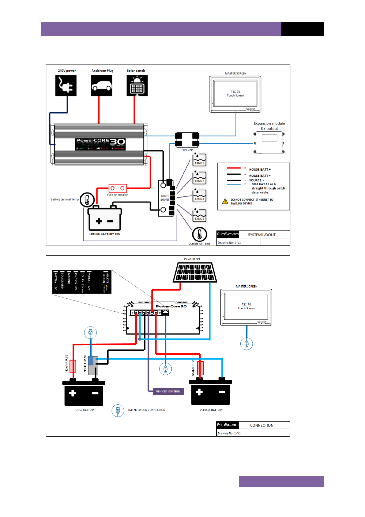
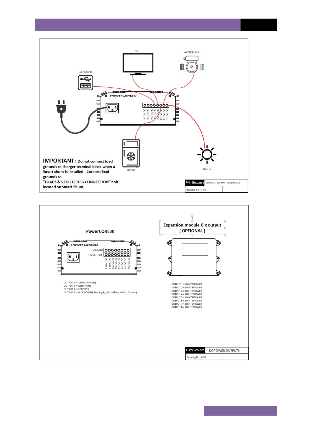
POWERCORE 30 INSTALLATION AND SETUP MANUAL
MOUNTING
It is very important to install the PowerCORE30 into a dry, well ventilated area to aid efficient
cooling. It is best to create the lowest possible ambient air temperature in the installation
location. Installing the PowerCORE30 close to outside walls in tight enclosed cabinets will allow
heat absorbed from outer walls to raise the temperature considerably. Continuous raised
ambient temperature will de-rate the PowerCORE30 charging ability, and cause the charger to
rest regularly. Choosing the correct location will aid charging, and prolong the life of the
PowerCORE30 . If your mounting location is tight in an enclosed compartment, ambient air
temperature will rise very quickly if ventilation is insufficient. It is recommended that a
ventilation 60mm hole be located under the PowerCORE 30 at the fan ventilation location to
allow heat to be directed out of the compartment.
CRITICAL NOTE : Do not install the PowerCORE30 in an area where fuel fumes or flammable
gas may be present. Serious injury or death could occur form fuel vapor explosion.
MOUNTING SURFACE
The mounting surface should be a solid surface that can hold the weight of the PowerCORE30
under extreme conditions of vibration. Ensure PowerCORE 30 is secured with appropriate size
screws.
The PowerCORE30 relies on under surface ventilation to allow heat to escape. The base of the
PowerCORE30, when mounted, will be 15mm from the mounting surface. This is sufficient space
for the cooling fan to extract heat from the PowerCORE30. It is critical not to obstruct the fan
area with carpet, felt or similar surfaces that may intrude on the 15mm distance. It is also
important to note, air extracted from the PowerCORE30, at times is hot air. Check the mounting
surface temperature during the first full charging cycles to ensure the mounting surface will
with stand the raised temperatures during Bulk charging.