Page 6of 15 IA0004
R&G
Unit 1, Shelley’s Lane, East Worldham, Alton, Hampshire, GU34 3AQ
Tel: +44 (0)1420 89007 Fax: +44 (0)1420 87301www.rg-racing.com Email: info@rg-racing.com
FITTING INSTRUCTIONS
FRONT INDICATORS (PICTURES 1-12)
•Using a ratchet with either a T30 torx or an 8mm hex socket, remove the 2 upper (see picture 1) and 2 lower bolts (see
picture 2) fixing the headlight in place.
•Carefully slide the headlight out, resting it on a towel placed on the front fender to prevent any damage, as shown in
picture 3.
•Using the ratchet with a T20 socket attached, remove the 2 upper (see picture 4) and 2 lower bolts (see picture 5)
securing the panel in place, then remove the bolts located beneath the indicators (see picture 6).
•Carefully remove the panel and disconnect the 2 original indicator connections shown in picture 7, taking note of the
corresponding indicator side and route that each connection delivers.
•Using a 13mm spanner, undo the nut securing each indicator and remove the indicators (see picture 8), taking care not
to bend the indicator wiring and making note of the order of the washers behind each nut (see picture 9).
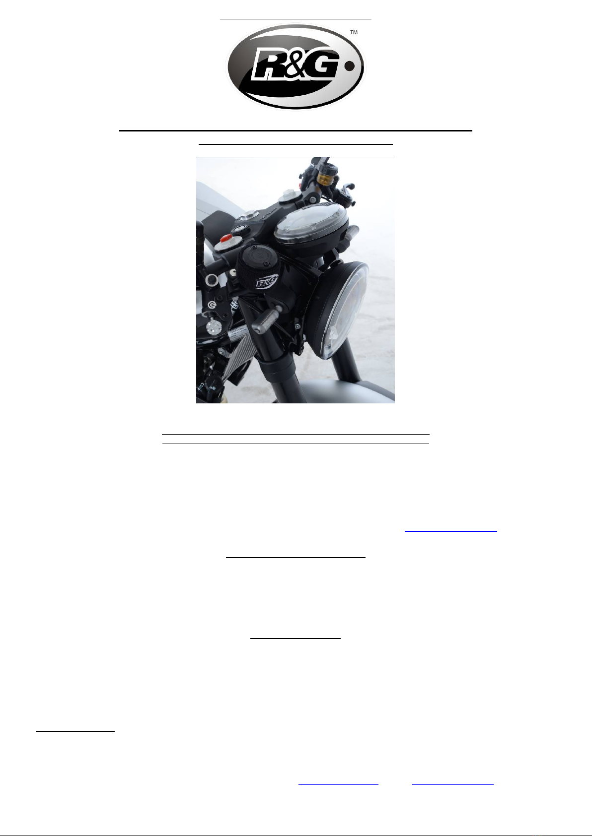
•Fit the new indicators of choice (R&G mini indicator product code RG370 for bulb type, RG371 for LED type or RG372
for the Aero Style LED type shown in picture 10), and secure using the OEM nut and washers (in the correct order).
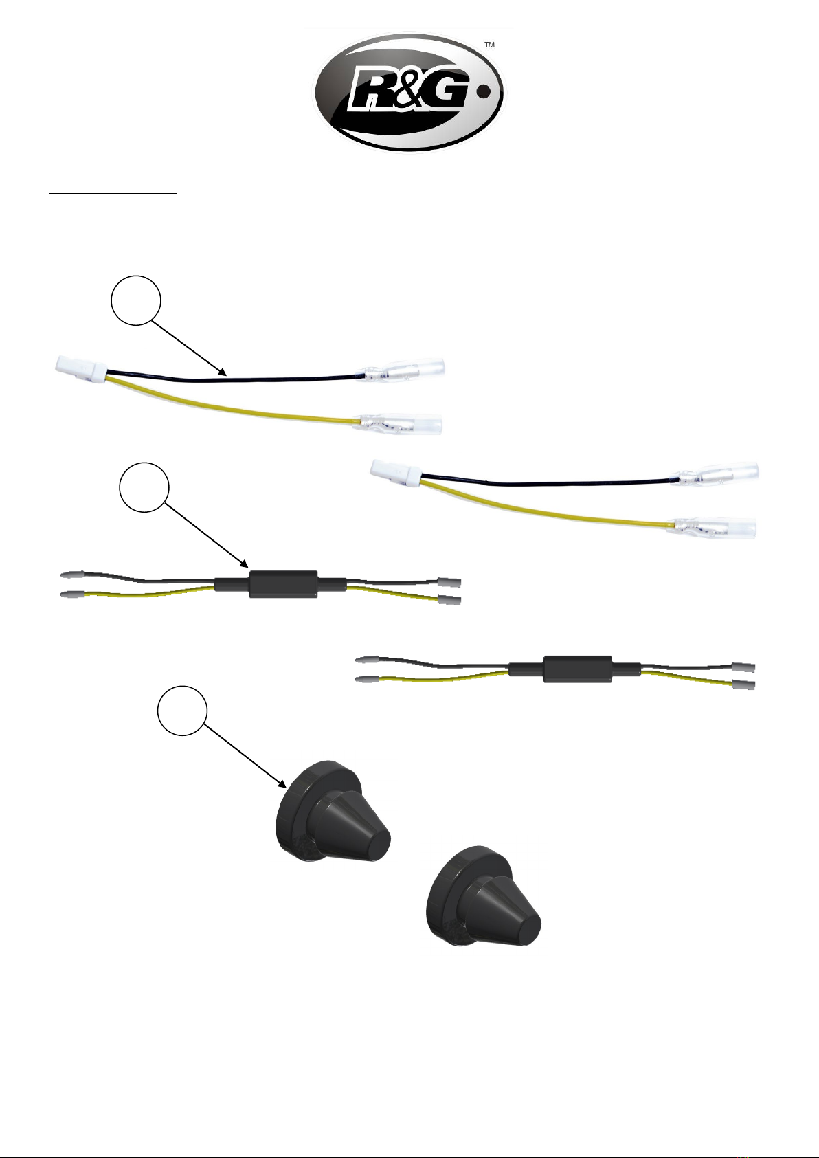
•Fit an indicator wiring connector (item 1) to both of the original indicator wiring loom connection points, then fit a flash
rate resistor (item 2) inline with each, as shown in picture 11, finally connecting the remaining bullet connectors to the
corresponding indicators.
•It is a good idea to test the indicators at this stage (if illumination fails, swap the connections around).
•Route and tidy the wiring as originally performed, then fit a rubber bung (item 3) in to each of the redundant indicator
locator holes, as shown in picture 12 (it helps if a small amount of liquid detergent is used).
•Refit the panel and headlight, finally testing the indicators for correct operation.
REAR INDICATORS (PICTURES 13-16)
•Remove the license plate, giving access to the 3 bolts shown in picture 13.
•Using a ratchet with either a T30 torx or an 8mm hex socket, remove the 3 bolts and gently pull the indicator/licence
plate illuminator bracket away from the main bracket as shown in picture 14, exposing the wiring for the indicators.
•Disconnect the 2 original indicator connections shown in picture 15, taking note of the corresponding indicator side
and route that each connection delivers.
•Using a 13mm spanner, undo the nut securing each indicator and remove the indicators (see picture 16), taking care not
to bend the indicator wiring and making note of the order of the washers behind each nut.
•Fit the new indicators of choice (R&G mini indicator product code RG370 for bulb type, RG371for LED type or RG372
for the Aero Style LED type as previously shown in picture 10) and secure using the OEM nut and washers (in the
correct order).
•Fit an indicator wiring connector (item 1) to both of the original indicator wiring loom connection points, then fit a flash
rate resistor (item 2) inline with each, as previously shown in picture 11, finally connecting the remaining bullet
connectors to the corresponding indicators.
•It is a good idea to test the indicators at this stage (if illumination fails, swap the connections around).
•Route and tidy the wiring as originally performed, fitting a rubber bung (item 3) in to each of the redundant indicator
locator holes, as previously shown in picture 12 (it helps if a small amount of liquid detergent is used).
•Refit the indicator/licence plate illuminator bracket to the main bracket, finally testing the indicators for correct
operation.
ISSUE 1 13/11/2018 (FB)
CONSUMER NOTICE
The catalogue description and any exhibition of samples are only broad indications of the Products and R&G may make design changes which do not diminish
their performance or visual appeal and supplying them in such state shall conform to the order. The Buyer acknowledges no representation or warranty (other than
as to title) has been given or will apply to the Products other than those in R&G’s order or confirmation and the Buyer confirms it has chosen the Products as being
of merchantable quality and suitable for its particular purposes. Where R&G fits the Products or undertakes other services it shall exercise reasonable skill and care