4
!
The Aoyue Int 863 IR-Preheating System is a reworking equipment that
combines infrared (IR) heating technology, enhanced pre-heating area, versatile
board holder, and profile control of heating in one sophisticated package. It is
designed for reworking double-sided, diverse technology printed circuit boards
(PCB) which utilizes traditional or lead free solder.
The system is equipped with a high powered IR-heating elements combined
with multiple types of preheating operation with built in safety control of heat
and over heat protection. Finally, the unique, innovative design with digital
control panel offers precision, safety, and ease of use to meet all reworking
requirements.
PRODUCT DESCRIPTION
FUNCTIONS and FEATURES
"! Microprocessor-controlled ESD safe unit.
"! Utilizes infrared heat wave technology.
"! Versatile board holder. To fit various board types
"! Enhanced pre-heating area to fit large PCBs.
"! Widely used for reworking BGAs, micro BGAs,!QFPs, PLCCs, SOICs, small SMD,
and other circuit board components.
"! Large pre-heating area minimizes board warping
"! Easy-to-adjust pre-heat temperatures with digital display.
"! Built in extra temperature sensor for more accurate monitoring of board temperature.
"! Built-in temperature sensor for stable (temperature) measurements.
"! Closed loop system for precise temperature control.
"! Profile adjustment functionality for automating reworking tasks under user de-
fined temperature and time settings.
"! Three modes of operation to suite different reworking requirements.
"! Temperature and Profile settings are stored into CPU memory for easy configu-
ration.
"! Compatible for use with either hot air or IR top heating systems. 9
!
OPERATING PROCEDURES
D. TYPE “1” OPERATION
Before proceeding with this type of operation, attach the first
external temperature probe to the underside of the PCB to be worked
on. The second probe can be placed near areas of interest.
This type of operation utilizes the first external temperature sensor
to control the heat. Using this type of operation allows us to closely
control the temperature at board level. While freeing up the second
external temperature probe for additional monitoring.
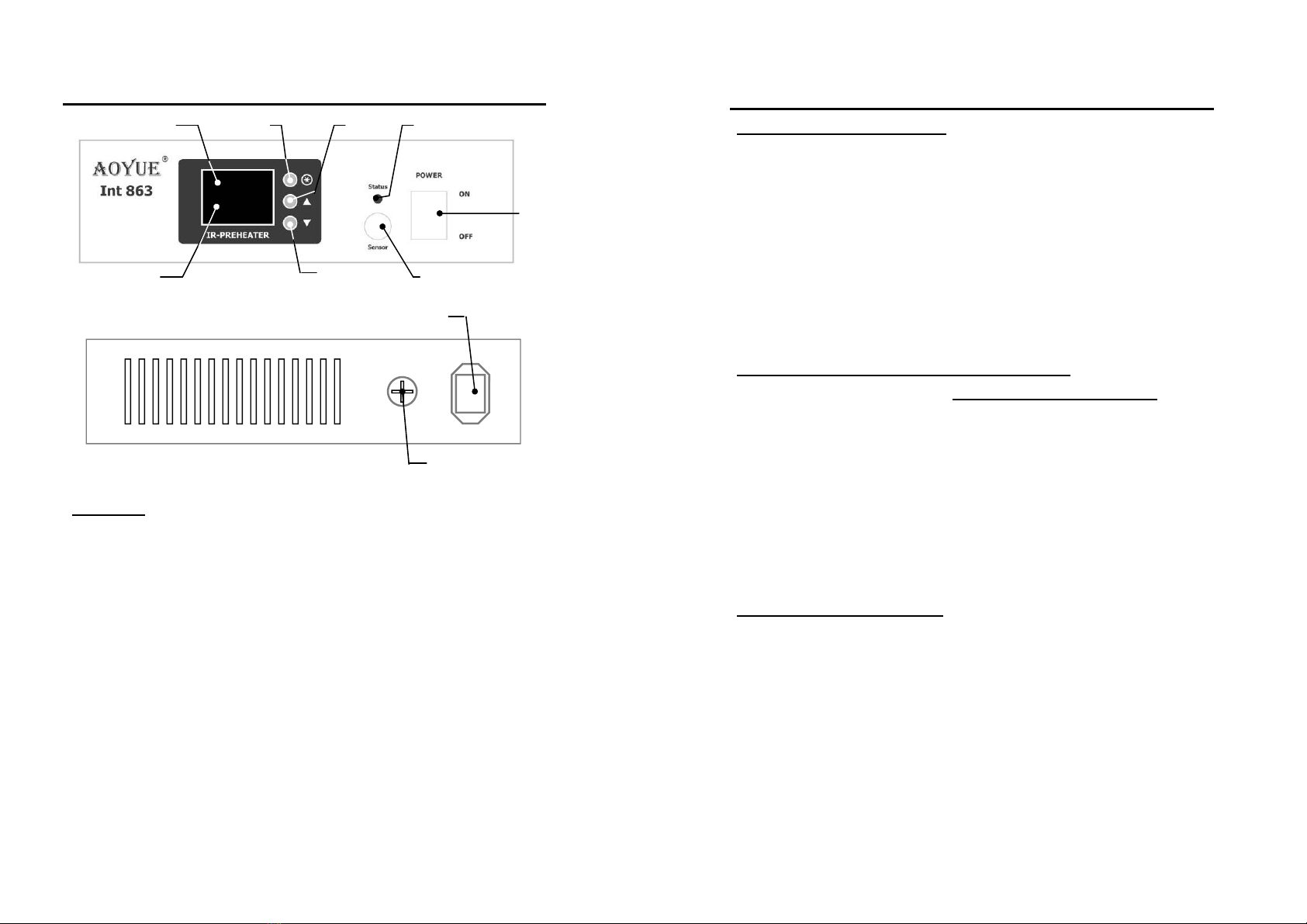
1. To set the desired temperature press the selection button
repeatedly until the top display shows “Set”. The bottom display
would show the current set temperature followed by a suffix “A”.
2. Press the increase or decrease button to adjust the set
temperature level. The set temperature is adjustable from 50 to
280 C in this type of operation.
3. For this type of operation we must closely monitor the actual
temperature of the first external temperature probe. To view the
actual temperature readout of this probe repeatedly press the
selection button until the top display shows the word “Act1”,
and the bottom display shows the actual temperature of first
external temperature probe followed by a suffix “b”.
4. To view the temperature of the second external temperature
probe or simultaneously view both external temperature probe's
temperature:
"! Repeatedly press the selection button until the top display
shows “Act 2” and bottom’s suffix shows “c” this displays the
second temperature probe.
"! Repeatedly press the selection button until the top shows the
first temperature probe with suffix “b” and the bottom shows the
second temperature probe with suffix “c”.
5. Under type “1” mode of operation it is not necessary to monitor
the internal temperature sensor’s read out.