aoyue INT883 User manual

12
BASICTROUBLESHOOTINGGUIDE
PROBLEM1:THEUNITHASNOPOWER
1. CheckiftheunitisswitchedON.
2. Checkthefuse.Replacewiththesametypeiffuseisblown.
3. Checkthepowercordandensuretherearenodisconnections.
4. Verifythattheunitisproperlyconnectedtothepowersource.
PROBLEM2:PANELDISPLAYS“Err”MESSAGES
DESCRIPTION:Displayshow“SEnS”“Err”messages.\
ERR0 —Firstexternaltemperatureprobenotdetected
ERR1 —Secondexternaltemperatureprobenotdetected
ERR2 —Internaltemperatureprobenotdetected
ERR3 —Firstexternaltemperatureprobenotattached.
SOLUTION:Turnoffpowerandbackon.
If err messages shows err0 or err1 check the connection of sensor to its
receptacle.Checkifthetemperatureprobetipisstillintact.
Iferrmessagesshowserr2internaltemperatureconnectormighthavecome
looseorneedstobereplaced.
If err messages shows err3, the first external temperature probe was not
detected,securetheexternaltemperatureontheundersideoftheboardtobe
workedon.
PROBLEM3:DISPLAYANDOTHERDEVICEOPERATION
ISSUES
SOLUTION:Turnoffpowerandbackon.
OTHERPROBLEMSNOTMENTIONED:
Contactthevendor.
IRPreheatingSystem
Int883
INSTRUCTIONMANUAL
ThankyouforpurchasingAoyueInt883IRPreheatingSystem.
Itisimportanttoreadthemanualbeforeusingtheequipment.
Pleasekeepmanualinaccessibleplaceforfuturereference.
This manual is designed to familiarize the technician with
the proper operation and maintenance of the equipment.
The “Care and Safety Precautions” section explains the
hazards of using any type of soldering or reworking device.
Please read carefully and observe the guidelines in order to
maximize usage and minimize the risk of injury or accidents .

2
TABLEOFCONTENTS
CARE & SAFETY PRECAUTIONS ………………………….. 3
PRODUCT DESCRIPTION …………………………………… 4
FUNCTIONS & FEATURES …………………………………… 4
PACKAGE INCLUSION …………………………………….. 5
SPECIFICATIONS ……………………………………………. 5
OPERATING PROCEDURES ……………………………... 611
BASIC TROUBLESHOOTING GUIDE …………………….... 12
11
OPERATINGPROCEDURES
6. Aftertheprocessisfinishthedisplaywillshow“End”, pressthe
increasebuttontosavetheprofileandexittoprofileadjustment
mode.
7. To exit beforethe process is finished press the increase button
whiletheprofileisrunning.Thesystemwouldexitandreturnto
profileadjustmentmode.
Note:There is a built in protection feature to automatically limit the
temperature rising slope to no more than 3 degrees per second.
Thereforebasedonyoursettime,themaximumtemperaturemaynot
reach250C.
Profileanalysis:
SEG1SEG2SEG3SEG4SEG5SEG6
050t060t080t050t040t60t
100C150C180C190C195C100C
Segmentone issetto 50secondstoreach 100C.Whichmeansafter
50seconds at the end of segment one the temperature shouldreach
100C. Then Segment two is set to 60 seconds to reach 150C, which
means by the end of 60 seconds the set temperature should reach
150C,soonandsoforth.
TochecktheslopefromsegmentTwo:
●150C100C=30C
●Timetoreach150Cissetto60seconds.
●Therefore the slope is 50/60= 0.833 degrees per second
increase.
Todeterminetheslopeifitisdecliningasseeninsegmentsix:
●195C100C=95C
●Timetoreach100Cissetto60seconds.
●Thereforetheslopeis95/60=1.58degreesperseconddecline.

10
OPERATINGPROCEDURES
D.TYPE“2”OPERATION
Before proceeding with this type of operation, attach the first
external temperature probe to the underside of the PCB to be
worked on. The second probe can be placed near areas of
interest.Suchasnearthecomponenttobeworkedon.
This type of operation utilizes the first external temperature
sensortocontroltheheat.Type“2”operationusestheprofileto
slowlycontroltheriseandfallofthetemperatureatboardlevel.
Whilethesecondexternaltemperatureprobecanbeattachedfor
additionalmonitoring.
1. Toentertype“2”mode.Select2attheinitialscreenthen
presstheselectbutton.The displaywouldchangeto “run
Prof”.Thissignifieswearenowinthetype“2”mode.
2. Toadjustthetimeandtemperatureprofileofeachsegment
presstheselectionbutton.Thetopdisplaywillshowwhich
segment “SEG1” we are currently adjusting while the
bottom display shows whether we are adjusting the time
(suffix“t”)ortemperature(suffix“C”).
3. Presstheincreaseordecreasebuttontoadjustthedesired
time and temperature. The set temperature is adjustable
from50to250Candtime5to200seconds.
4. To start preheating with the profile, repeatedly press the
selection button until the display shows the word “Run
Prof” then press the increase button. A 3 second
countdown will commence before automated reworking
starts.
5. Toseetherunningtime,or currentsegmentthesystemis
processing or the temperature of the external temperature
probes. repeatedly press the selection button to switch
between different views. Follow the suffix guide to
determinedisplayedtemperature.
3
CAREandSAFETYPRECAUTIONS
CAUTION:Improperusagecancauseinjuryandphysicaldamage.
Foryourownsafety,pleaseobservethefollowingprecautions.
●Temperaturemayreachashighas500°CwhenturnedON.
Donottouchtheheatingelementinsidethepreheater.
Donotexposeskintoinfraredlightforlongperiods.
Prolongedexposuremaydamagetheskintissue.
●Handlewithcare
Neverdroporsharplyjolttheunit.
Contains delicate parts such as IR tubes that may break if
theunitisdropped
Donotspillanyliquidtothesystem.
●Do not tamper the electrical control unit or any wiring inside
thedevice.
●Disconnectplugfrommainpowersourceifthedevicewillnotbe
usedforalongperiod.
Turnoffpowerduringbreaks,ifpossible.
●Allow ample time for the equipment to cool down before
commencingmaintenance.
●Useonlygenuinereplacementparts.Turnoffpowerandletthe
unitcooldownbeforereplacinganycomponent.

4
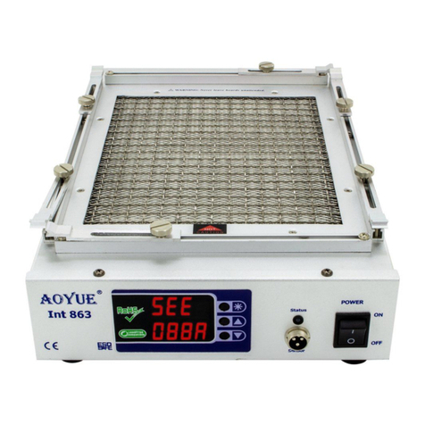
TheAoyueInt883IRPreheatingSystemisareworkingequipmentthatcom
binesinfrared(IR)heatingtechnology,enhancedpreheatingarea,versatileboard
holder,andprofilecontrolofheatinginonesophisticatedpackage.Itis designed
for reworking doublesided, diverse technology printed circuit boards (PCB)
whichutilizestraditionalorleadfreesolder.
ThesystemisequippedwithahighpoweredIRheatingelementscombined
with multiple types of preheating operation with built in safety control of heat
andoverheatprotection. Finally,theunique,innovativedesignwithdigitalcon
trolpaneloffersprecision,safety,andeaseofusetomeetallreworking
requirements.
PRODUCTDESCRIPTION
FUNCTIONSandFEATURES
●MicroprocessorcontrolledESDsafeunit.
●Utilizesinfraredheatwavetechnology.
●Versatileboardholder.Tofitvariousboardtypes
●EnhancedpreheatingareatofitlargePCBs.
●WidelyusedforreworkingBGAs,microBGAs, QFPs,PLCCs,SOICs,smallSMD,
andothercircuitboardcomponents.
●Largepreheatingareaminimizesboardwarping
●Easytoadjustpreheattemperatureswithdigitaldisplay.
●Builtinextratemperaturesensorformoreaccuratemonitoringofboardtemperature.
●Builtintemperaturesensorforstable(temperature)measurements.
●Closedloopsystemforprecisetemperaturecontrol.
●Profile adjustment functionality for automating reworking tasks under user
definedtemperatureandtimesettings.
●Threemodesofoperationtosuitedifferentreworkingrequirements.
●Temperature and Profile settings are stored into CPU memory for easy
configuration.
●CompatibleforusewitheitherhotairorIRtopheatingsystems.
9
OPERATINGPROCEDURES
D.TYPE“1”OPERATION
Beforeproceedingwiththistypeofoperation,attachthefirstexternal
temperature probeto the underside of the PCB to be worked on. The
secondprobecanbeplacednearareasofinterest.
Thistypeofoperationutilizesthefirstexternaltemperaturesensorto
controltheheat.Usingthistypeofoperationallowsustocloselycontrol
the temperature at board level. While freeing up the second external
temperatureprobeforadditionalmonitoring.
1. To set the desired temperature press the selection button
repeatedlyuntilthetop displayshows“Set”.Thebottomdisplay
wouldshowthecurrentsettemperaturefollowedbyasuffix“A”.
2. Press the increase or decrease button to adjust the set
temperature level. The set temperature is adjustable from 50 to
280Cinthistypeofoperation.
3. For this type of operation we must closely monitor the actual
temperatureof the first externaltemperature probe. To view the
actual temperature readout of this probe repeatedly press the
selectionbuttonuntilthetopdisplayshowstheword“Act1”,and
thebottomdisplayshowstheactualtemperatureoffirst external
temperatureprobefollowedbyasuffix“b”.
4. To view the temperature of the second external temperature
probe or simultaneously view both external temperature probe's
temperature:
●Repeatedlypresstheselectionbuttonuntilthetopdisplayshows
“Act 2” and bottom’s suffix shows “c” this displays the second
temperatureprobe.
●Repeatedlypresstheselectionbuttonuntilthetopshowsthefirst
temperature probe with suffix “b” and the bottom shows the
secondtemperatureprobewithsuffix“c”.
5. Undertype“1” mode of operation it is not necessary to monitor
theinternaltemperaturesensor’sreadout.

8
OPERATINGPROCEDURES
2. Press the increase or decrease button to adjust the set
temperature level.The set temperature is adjustable from
50to400Cinthistypeofoperation.
3. To view the actual temperature read by the internal
temperature probe, repeatedly press the selection button
until the top display shows the word “Act3”, and the
bottom display shows the actual temperature of internal
temperatureprobefollowedbyasuffix“d”.
4. To view the actual temperature read by the first external
temperature probe, repeatedly press the selection button
until the top display shows the word “Act1”, and the
bottom display shows the actual temperature of first
externaltemperatureprobefollowedbyasuffix“b”.
5. ToviewtheactualtemperaturereadbytheSecondexternal
temperature probe, repeatedly press the selection button
until the top display shows the word “Act2”, and the
bottom display shows the actual temperature of second
externaltemperatureprobefollowedbyasuffix“c”.
6. Tosimultaneouslyviewtheactualtemperaturereadbythe
first and Second external temperature probe, repeatedly
press the selectionbuttonuntil thetopdisplayshowsthe
actual temperature of first external temperature probe
followedbyasuffix“b”.andthebottomdisplayshowsthe
actual temperature of second external temperature probe
followedbyasuffix“c”.
Note:Externaltemperatureprobesarecolorcoded.
Thefirstexternaltemperatureprobeistheredandbluepair.
Whilethesecondexternaltemperatureprobeisallwhite.
5
SPECIFICATIONS
PowerInput: Availablein110V/220V
Dimensions: 520(l)x370(w)x100(h)mm
PowerConsumption: 1500W(maximum)
TemperatureRange: 50°C400°C(^maximum)
HeatingElement: IRHeating
PreHeatingArea: 310mmx310mm
PACKAGEINCLUSION
^Dependsontypeofoperation
*Specificationssubjecttochangewithoutpriornotice
InstructionManual
883MainStation
Temperatureprobe

6
ControlPanelGuide
LEGEND:
1—DigitalDisplay 6—ExternalSensorconnector
1.aTopDisplay7—MainPowerswitch.
1.bBottomDisplay8—Powercordattachment.
2—Selectionbutton.9— Fuseholder.
3—IncreaseButton/Enterbutton.
4—DecreaseButton.
5—StatusLED.
Suffixguide:
A - Settemperaturefortype0and1operation.
b - ActualTemperatureofSensor1(red/bluewire)
c- ActualTemperatureofSensor2(whitewire)
D- ActualTemperatureofInternalSensor
C- SetTemperatureforprofile.
t- Setduration/time(seconds)forprofile.
1.a 5
4
3
2
6
7
FrontPanel
BackPanel9
8
1.b
7
OPERATINGPROCEDURES
A.INITIALPROCEDURES
1. Makesureallswitchesaredeactivated.
2. Attachexternalsensorprobestothethreepinsocket.(#6 on
controlpanelguide)
3. Attach power cord to the power cord attachment (#8 on
controlpanelguide)
4. Plugthedevicetothemainpowersource.
5. To turn the unit ON. Toggle the main power switch to ON
position(#7oncontrolpanelguide)
B.OPERATIONTYPE(MODE)SELECTION
1. Followinitialprocedures,“A.INITIALPROCEDURES”.
2. The display would show “TYPE 0”, which means Type 0
operationwillbeused.Toselect between types0to 2.Press
the increase or decrease buttons (#3 & #4 of control panel
guide).
3. To confirm selection and enter into operation mode using the
selected type. Press theselection button.(#2 of control panel
guide)
C.TYPE“0”OPERATION
Thistype ofoperationutilizesthe internaltemperaturesensor
to control the heat. Using this type frees up the two extra
externaltemperatureprobesforadditionalmonitoring.Attachthe
two extra temperature probes to areas of interest such as the
bottomoftheboardandtopoftheboardnearthecomponentsto
beworkedonformonitoring.
1. To set the desired temperature press the selection button
repeatedly until the top display shows “Set”. The bottom
displaywouldshowthecurrentsettemperaturefollowedby
asuffix“A”.
Table of contents
Other aoyue Laboratory Equipment manuals