APAR AR915 Installation instructions

APAR - SALES OFFICE
05-090 Raszyn, ul. Gałczyńskiego 6
Tel. +48 22 853-48-56, +48 22 853-49-30, +48 22 101-27-31
E-mail: auto[email protected]
Website: www.apar.pl
USER INSTRUCTION
TEMPERATURE CALIBRATOR
AR915
Version 1.1.0
2015-06-12

-1 -
Thank you for choosing our product.
This instruction is intended to facilitate correct operation, safe use,
and taking full advantage of the calibrator's functionalities.
Before you start the device, please read and
understand this instruction.
In the event of any additional questions, please contact our technical
adviser.
CONTENTS
1. PRINCIPLES OF SAFE USE.............................................................................................2
2. GENERAL CHARACTERISTICS OF THE CALIBRATOR...........................................2
3. TECHNICAL DATA.............................................................................................................3
4. DIMENSIONS OF THE HOUSING AND DESCRIPTION OF CONNECTIONS AND
EXTERNAL ELEMENTS……………………………………………...…………………..4
5. BUTTON FUNCTIONS .......................................................................................................5
6. PROGRAMMING OF CONFIGURATION PARAMETERS...........................................5
7. SETTING OUTPUT SIGNAL VALUES............................................................................7
8. LIST OF MESSAGES AND ERRORS .............................................................................7
9. USER'S NOTES...................................................................................................................7
Please pay particular attention to the text marked with this sign.
The manufacturer reserves the right to make changes to the design and the programming of the device without any
deterioration of the technical parameters.

-2 -
1. PRINCIPLES OF SAFE USE
before you start to use the device, become familiar with the present instructions;
ensure proper operating conditions, as specified in the user’s technical data (humidity, temperature)
The device is designed so as to ensure an appropriate level of immunity to most interferences that may
occur in industrial environments. In environments of unknown level of interferences,
it is recommended to implement the following measures so as to prevent potential interference with the
operation of the device:
avoid running instrument (signal) cables in the direct vicinity of and parallel to power and supply cables;
it is recommended to use twisted pair signal cables;
in the case of sensing resistors in 3-wire connections, use identical wires;
avoid proximity of remotely controlled devices, electromagnetic meters, high power loads, loads with
phase or group power control, and other devices that cause high impulse disturbances;
2.GENERAL CHARACTERISTICS OF THE CALIBRATOR
the purpose of the device is to measure and simulate temperature sensors
universal input/output (programmed from the keyboard):
- thermoresistant...Pt100, Ni100, for measurements, automatic detection of a 2- or 3-wire connection of
the sensor with line resistance compensation
- thermocouples...J, K, S, B, R, T, E, N, automatic or constant compensation of reference joint
temperature
- linear…………... voltage (mV), resistance
an ergonomic manual housing of small size and weight, with rubber anti-slip side grips
simple and reliable laboratory banana connectors
a clearly visible LCD display and a functional keyboard
battery (2 x 1.5 V) or rechargeable battery (2 x 1.2 V NiMH) power supply, AA type
long operation on a fully charged set of batteries
automatic power supply cutoff at low battery charging level
automatic shutdown after a preset idle time
possibility to test measurement devices and temperature sensors
diagnostic functions facilitating detections such defects in tested circuits as:
- lack of excessive value of current polarizing a resistance sensor (in a simulation)
- short circuits in a voltage signal measurement circuit (in a simulation of thermocouples and mV)
- short circuits or interruptions in sensor circuits (in measurements)
quick and simple readout:
- type of sensor set
- working direction (input/output)
- battery charging level
- current polarizing a resistance sensor (in a simulation)
- type of detected connection in a resistance sensor (2- and 3-wire)
- reference joint temperature in a thermocouple sensor (in a simulation and in measurements)
programmable range and step of output signal changes and other configuration parameters, such as:
resolution of indications, calibration of the zero point and the gain of the measured or set signal,
keyboard block, automatic device shutdown delay, etc.
settings in °C ,Ω, mV
programmable password protection of configuration parameters
high resistance to interferences present in industrial environments
protection against incorrect battery polarity
NOTE:
After the calibrator is switched on in the measurement mode, an error signal may be shown in the display
that indicates that no sensor or a sensor different than the factory-defined sensor in the configuration
parameter is connected to the device. If this happens, connect the proper sensor or set the correct
parameter 0: StYP (chapter 6, Table 1)

-3 -
3.
TECHNICAL DATA
Operation mode (set from the keyboard)............ input (measurement) or output (simulation)
Universal input/output (programmable with the parameter 0:StYP), measurement and settings range:
RTD : - Pt100 (3- or 2-wire)....-100 ÷ 850 °C (factory setting of the sensor)
- Ni100 (3- or 2-wire)..... -50 ÷ 170 °C
-
Pt100, Ni100, for measurements, automatic detection of a 2- or 3-wire connection of the
sensor with line resistance compensation, automatic for 3-wire version, constant for 2-wire
version (parameter 1:rrtd)
Thermocouple:
- thermocouple J ............................ -40 ÷ 800 °C
- thermocouple K ........................... -40 ÷ 1200 °C
- thermocouple S ........................... -40 ÷ 1600 °C
- thermocouple B ........................... 300 ÷ 1800 °C
- thermocouple R ........................... -40 ÷ 1600 °C
- thermocouple T ........................... -25 ÷ 350 °C
- thermocouple E ........................... -50 ÷ 750 °C
- thermocouple N ........................... -80 ÷ 1300 °C
-
compensation of cold thermocouple end temperature, automatic or constant
(programmable with parameters 2: 2: cJtY and 3: cJtE, see chapter 6, Table 1)
Line: - voltage ............................................... -5 ÷ 55 mV
- resistance ......................................... .10 ÷ 540 Ω(measurement)
0 ÷ 1,000/Ip [Ω]≤3,200 Ω(setting)
Ip - output polarizing current [mA]
Leads resistance for RTD ................................. Rd < 25 Ω(for each line)
Resistance input current (RTD, Ω).................... ~250 µA (for measurements)
Output polarizing current Ip RTD, Ω.................100 ÷ 1,900 µA (input current in resistance simulations) (1)
Basic processing error (at ambient temperature equal to 25 °C)
- measurement: - Pt100, -5÷55 mV, 10÷540 Ω.......≤0.2% of sensor range ±1 digit
- Ni100, all thermocouples………...≤0.3% of sensor range ±1 digit
- setting (simulation):- Pt100, Ni100....................… ≤2 °C for Ip > 200 µA and ≤3 °C for Ip < 200 µA
- J, K, E, N, 55 mV, 0÷3.2 kΩ.......… ≤0.2% for sensor range and ≤1.5 Ωfor 0÷3.2 kΩ
- S, B, R, T...................................….≤0.3% of sensor range
Additional error for setting Pt100,Ni100, 0÷3,2kΩ… ≤2,5°C or ≤1Ω(nonlinearity)
Additional error for thermocouple inputs ...........….≤2 °C (present only in automatic compensation
of cold tip temperature)
Additional error from temperature changes........….≤0.01% of the sensor range/°C
Resolution of indications.....................................… 0.1 °C or 1 °C (programmable with parameter 6: dot)
Resolution of settings in simulations...............…… 0.5 ÷ 200.0 °C, set with parameter 9:StEP, default value 1°C
Response time for measurements (10÷90%)....…… 0.7 ÷ 2.3 s, set with parameter 5:FiLt, default value 1.3 s
LCD display (7-segment, 4 digits)
- range of indications ....................................….. -1999 ÷ 9999
- digit height .................................................….. 10 mm
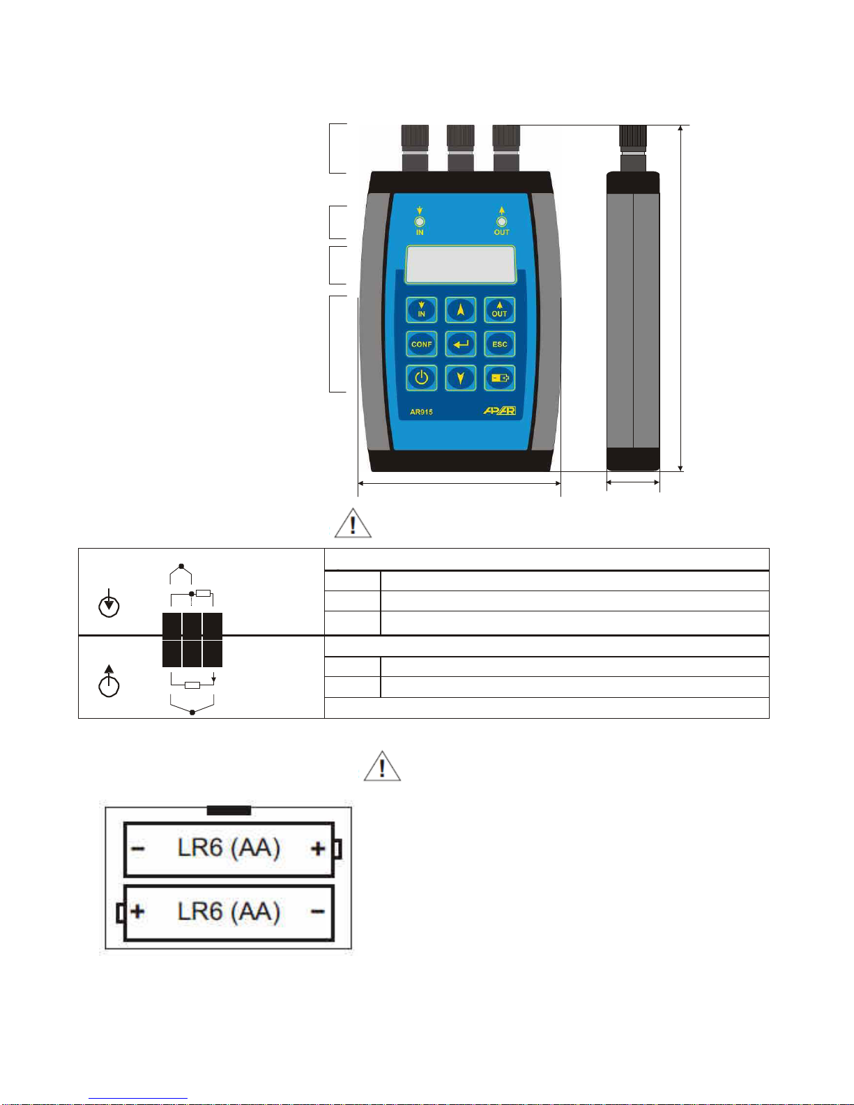
Power supply (regular or rechargeable batteries) 2 x 1.5 V (2 x 1.2 V NiMH), type AA (LR6) (2)
Operation time...................................................…..300 ÷ 400 hours(with rechargeable batteries 2 x 1.2 V/2,5 Ah)
Operating temperature range ...........................…..0 ÷ 50 °C
Relative humidity range ...................................…. 0 ÷ 90 % (no condensation)
Housing .............................................................…. manual, ABS material
Dimensions........................................................….136 x 80 x 25 mm
Protection rating................................................… IP43
Operating position ............................................… any
Weight................................................................…~130 g (w/o batteries), ~165 g (w/ batteries)
Electromagnetic compatibility (EMC)
-
immunity: according to the PN-EN 61000-6-2:2002(U) standard
-
emissivity: according to the PN-EN 61000-6-4:2002(U) standard
(1) - simulation of resistance (RTD, Ω)does not work for multiplexed inputs (pulse IP current)
(2) - when replacing the batteries, pay attention to the polarity shown in the battery compartment

-4 -
3
2
1
3
2
1
4. DIMENSIONS OF THE HOUSING AND DESCRIPTION OF CONNECTIONS AND
EXTERNAL ELEMENTS
input/output
connections
3 2 1
LED diodes - operating mode indication
(input - IN, output - OUT)
LCD display
136
keyboard
80 25
Dimensions in mm
DESCRIPTION OF CONNECTIONS
INPUT
IN
_
TC, mV
Pt100, Ni100,
termin
als
description
1-2-3 input Pt100, Ni100, Pt500, Pt1000, resistance, 3-wire
1-3 input Pt100, Ni100, Pt500, Pt1000, resistance, 2-wire
2
-
3
thermocouple input (J, K, S, B, R, T, E, N) and 0÷55 mV
OUTPUT
OUT
Ip Pt100, Ni100,Ω
TC, mV
+
termin
als
description
1-3 output Pt100, Ni100, resistance
1
Ω
-3 thermocouple output (J, K, S, B, R, T, E, N) and 0÷55 mV
Ip - resistance output polarizing current in simulations
BATTERY INSTALLATION METHOD
View from the bottom of the device after the cover is
opened

-5 -
5. BUTTON FUNCTIONS
Button Function
- switches the calibrator on/off (press for more than 1 second)
or
- sets the operating mode: input - IN (measurement) or output - OUT (simulation)
- accesses the parameter configuration mode (press for more than 2 seconds in the
measured/set value display mode),
- shows the type of sensor set (in the measured/set value display mode)
- edits the current parameter in the configuration mode (display of the parameter value),
- approves the edited parameter value, (in the text, it is designated as SET),
- increases the set value by the preset step (parameter 9:StEP, chapter 6) in simulations
- increases the parameter value in the configuration mode, (in the text, it is designated as ),
- moves to the next parameter,
- decreases the set value (parameter 10:SEt, chapter6) by the preset step in simulations
- decreases the parameter value in the configuration mode, (in the text, it is designated as
), moves to the previous parameter,
- cancels the change of the edited parameter (and displays the parameter name again)
- returns to the measured/set value display mode (must be pressed for more than 1 second)
+ - changes the set value (10:SEt) to the upper limit of the range of the simulated sensor or to
the value of parameter 8:LiHi (the lower of the two values)
+ - changes the set value (10:SEt) to the lower limit of the range of the simulated sensor or
to the value of parameter 7:LiLo (higher of the values)
- shows the battery voltage:- 0% - voltage < 2.2 V (low level),
- 100 % - voltage > 2.6 V (high level)
+ - shows the current polarizing a resistance sensor in a simulation in [µA]
- type of detected connection for a resistance sensor (2- and 3-wire) in measurements
- reference joint temperature for a thermocouple sensor (in simulations and in
measurements)
+ - shows the calibrator software version
6. PROGRAMMING OF CONFIGURATION PARAMETERS
press the CONF button until (approx. 2 s) the display shows the following temporary message:
ConF or CodE (if password protection is set, i.e. parameter 15:Prot=on),
if password protection is on, the display shows 0000 with the 1st digit blinking; use keys and to
enter the password (default parameter 16:PASS=1111), to move to the successive positions and to
approve the entered code, use the SET key,
after you enter the configuration menu, the mnemonic name of the first parameter is displayed (StYP),
by pressing the button, you can move to the next parameter, and by pressing the button - to the
previous parameter (StYp↔rrtd↔cJtY...), a list of the configuration parameters is presented in Table 1.
to change or view the value of the current parameter, press SET (edition of the parameter),
by using or , you can change the value of the current parameter,
by pressing SET again, you can save the edited value and return to the parameter name display
(e.g.FiLt),
in the parameter edition mode, by pressing ESC for a short time, you can cancel the changes and
return to the parameter name display mode,
you can exit the configuration parameters programming mode by pressing ESC for a long time, or
automatically after approx.2 minutes of idle condition,
in the normal mode, the measured or set value is displayed,
in the event of a difference between the measured/set value and the actual one, it is possible to tune the
zero point and the sensitivity to the specific sensors - parameters 11: cALo (zero point)
and 12: cALG (sensitivity).

-6 -
Table 1.Configuration parameters
Parameter name change -
or
Parameter name readout/saving -
SET,
Parameter value change - or
Settings
No. Name Description of parameter Parameter value and range of
variability default user’s
0 StYP type of
sensor
(input and
output)
RTD Pt= Pt100, ni= Ni100 Pt
Resistance rES= 10÷540 Ω-IN or 0÷3200 Ω
(max)-OUT
Thermocouple tc-J=J, tc-K= K, tc-S= S, tc-b=
B, tc-r= R, tc-t= T, tc-E= E,
tc-n= N
Voltage u55= -5÷55 mV
1 rrtd total resistance of 2 lines for
the input Pt, ni and rES 0.0÷ 50.00 Ω(line resistance
compensation for a 2-wire
connection in measurements
0.00 Ω
2 cJtY type of compensation of
temperature of cold tips Auto= automatic, conS= constant
(defined by parameter 3: cJtE)
Auto
3 cJtE temperature of cold tips 0.0÷ 50.0°C (applies to
thermocouples for cJtY= conS)
25.0 °C
4 ModE calibrator operation mode in= measurement (input),
out= simulation (output)
in
5 FiLt filtration rate
(1)
4÷ 15 8
6 dot resolution of indications
(2)
0= 1 °C, 1= 0.1 °C 1= 0.1 °C
7 LiLo lower setting limit for SEt 00.0 ÷ 3200 00.0 °C
8 LiHi upper setting limit for SEt 00.0 ÷ 3200 3200
9 StEP value change step SEt 0.5÷ 200.0 1.0°C
10 SEt set value in the range of the sensor or LiLo÷
LiHi
100.0 °C
11 cALo zero point offset -50.0÷ 50.0°C 0.0 °C
12 cALG gain (sensitivity) -85.0÷ 115.0%, 100.0 %
13 bLoc keyboard keys lock
IN
,
OUT
and 10:SET oFF= no lock, inou= lock IN and
OUT
SEt= lock SET, ALL= lock IN,OUT,
SEt
oFF
14 PASS password
(3)
0÷ 9999 1111
15 Prot password protection
(3)
oFF= off, on= on oFF
16 toFF auto-off delay
(4)
0÷ 240 min (0- function not active) 0
Notes:
(1) - for FiLt=4 the response time is approx.0.7 s, for FiLt=15 - approx. 2.3 s. A higher filtration
rate means a smoother measurement value and a longer response time. The parameter
also applies to measurements of the current polarizing the (thermo)resistance output (in the
simulation mode).
(2) - does not apply to the resistance sensor (StYP=rES) and the voltage sensor (StYP=u55)
for which the resolution is equal to, respectively:0.1Ω and 0.01 mV,
(3) - when Prot=oFF, access to the parameter configuration does not require a password,
(4) - this is the time from the last use of any button

-7 -
7. SETTING OUTPUT SIGNAL VALUES
By pushing or in the simulation mode (OUT), you can change the set value by the preset step
(parameter 9:StEP). By pressing SET and at the same time, you set the output to the lower of the following
values: the upper limit of the simulated sensor or the value of parameter 8:LiHi; by pressing SET + at the
same time, you set the output to the higher of the following values: the lower limit of the simulated sensor or
the value of parameter 7:LiLo. Also, the output signal can be set in the parameter programming mode
(parameter 10:SEt).
8. LIST OF MESSAGES AND ERRORS
^^^^…..upper segments of the display - the upper limit of the sensor range is exceeded or the sensor is
defective,
____…..lower segments of the display - the lower limit of the sensor range is exceeded or the sensor is
defective,
ConF... the parameter configuration mode is entered,
CodE... the mode for entering the password for access to the configuration parameters is entered,
Err....... an incorrect password for access to the configuration parameters was entered,
----....... initiation of the operating mode (input/output),
E-iH..... the value of the current polarizing the output of the (thermo)resistance sensor is exceeded
(Ip > 1.5 mA)
E-iP…..reverse polarization of the output of the (thermo)resistance sector (wrong connection to the
terminals),
200.0... blinking set value - no current polarizing the output of the (thermo)resistance sensor,
(Ip < 25 µA)
E-rL..... a short circuit in the output of the thermocouple sensor or the voltage sensor,
PoFF... the calibrator was switched off (manually or automatically due to low battery voltage),
LbAt…...battery voltage too low (replace batteries with new ones).
9. USER'S NOTES

-8 -
Table of contents
Other APAR Test Equipment manuals