Note: The remote vent v lve m y be ddition lly inst lled between the integrity test instrument
nd the P lltronic Flow Check II unit (or between the integrity test instrument nd the upstre m
volume, if required) so th t le ks within the remote v lve m y be detected. Therefore, should
the Flow Check test f il, ple se repe t the Flow Check test without the remote vent v lve
tt ched to determine whether the remote vent v lve is the c use of the f ilure or not.
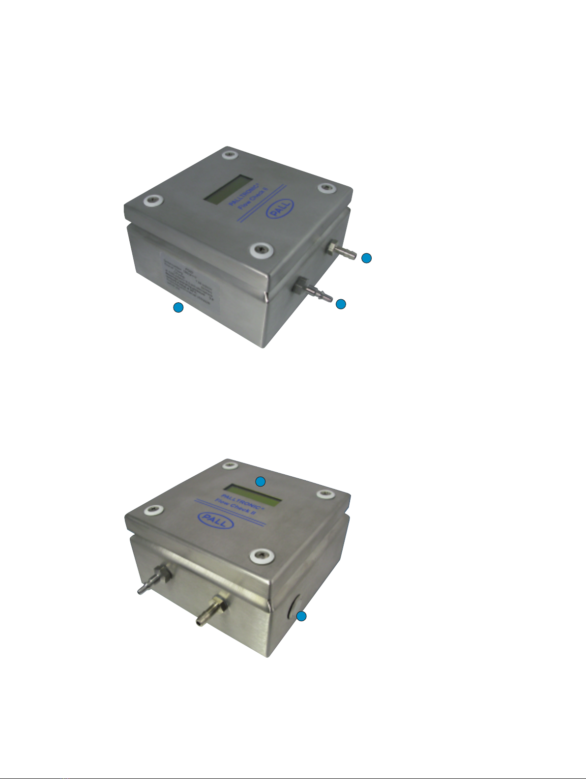
• Ensure that the ‘VENT’ connection on the Palltronic Flow Check II unit is open to atmosphere.
• It is recommended that the red pneumatic tubing supplied with the Palltronic Flow Check II
unit be used exclusively for this purpose. It is also highly recommended that this tubing is
kept clean and dry. In this way accidental contamination of the internal capillary within the unit
can be mitigated.
Import nt: Although the P lltronic Flow Check II unit h s n integr l G skleen filter in order to
limit the possibility of cont min ting the intern l c pill ry, the oper tor should still t ke gre t
c re to void cont min tion. Should either the integr l filter or the c pill ry become
cont min ted, d m ged or blocked, the oper tion of the P lltronic Flow Check II unit will be
severely compromised.
3.4 Performing a ‘Flow Check’ Test
Note: The following test procedure ssumes th t the integrity test instrument provides
dedic ted ‘Flow Check’ test (see your integrity test instrument Oper ting Instructions for the
instrument c p bilities). If the dedic ted ‘Flow Check’ test is not v il ble, ‘Forw rd Flow’ test
m y be used inste d. In this situ tion, the ‘Expected Flow’ becomes the ‘M ximum Flow’ test
p r meter nd the p ss/f il result t the end of the test should be ignored: refer inste d to
Section 3.5 for the interpret tion of the result.
• Select a ‘Flow Check’ test on the Palltronic integrity test instrument (for more information, see
the relevant Operating Instructions for your integrity test instrument).
• Enter the following test parameters (and where indicated by 1below, using the relevant values
displayed by the Palltronic Flow Check II unit in use, see also Section 3.2.
Test Pressure1: 2000 mbar (29 psi)
Test Time: 600 seconds
Ref. Unit Serial No.1: 1234567
Expected Flow:1X.XX m /min
• Press the ‘Start’ button on the Palltronic integrity test instrument to activate the
‘Flow Check’ test.
• On completion of the test (i.e. after the test time has elapsed), the measured value will be
given with a percent deviation value between the measured and the expected values (if the
dedicated ‘Flow Check’ test has been used).
Note: After use, the P lltronic Flow Check II unit should be c refully disconnected from the
P lltronic integrity test instrument, the protective c ps should be repl ced on the inlet nd vent
ports nd the unit stored in dry pl ce t room temper ture.
3.5 Understanding the Test Results
The test result will be reported as a flow rate value. Under stable test conditions, the Palltronic
integrity test instrument should be within ± 5% of the expected flow value displayed by the
Flow Check II unit.
The expected flow value is calculated from the reference value (as shown on the side of the
Palltronic Flow Check II unit and on the calibration certificate provided with the Palltronic Flow
Check II unit) by compensating for any variation in atmospheric pressure.
If the dedicated ‘Flow Check’ test has been used, the percent deviation value will be calculated
and presented by the integrity test instrument. If, however, the integrity test instrument does not
www.pall.com/b opharm 7