APAR AR904 User manual

INSTRUCTION MANUAL
PROGRAMMING DEVICE FOR ANALOGUE
SIGNALS
AR904
Version 1.2.0 May 26, 2014

2
Thank you for choosing our products.
This manual will aid you with a correct and safe
use and full utilisation of the programming device.
Before installation and use
please read and understand this manual.
If you have any further questions, please contact your technical advisor.
TABLE OF CONTENTS
1. SAFETY RULES ........................................................................................................... 3
2. INSTALLATION GUIDELINES ...................................................................................... 3
3. GENERAL CHARACTERISTICS OF THE PROGRAMMING DEVICE.................................. 3
4. CONTENTS OF THE KIT.............................................................................................. 4
5. TECHNICAL SPECIFICATIONS ..................................................................................... 4
6. ENCLOSURE MEASUREMENTS AND INSTALLATION DATA .......................................... 5
7. DESCRIPTION OF TERMINALS AND ELECTRICAL CONNECTIONS ................................ 5
8. ENCLOSURE MEASUREMENTS AND INSTALLATION DATA .......................................... 5
9. CHANGING THE OUTPUT SETPOINT .......................................................................... 6
10. SETTING CONFIGURATION PARAMETERS ................................................................ 7
11. SOFT START/STOP AND TRIANGLE WAVE GENERATOR .......................................... 9
12. MESSAGES AND ERRORS ........................................................................................ 10
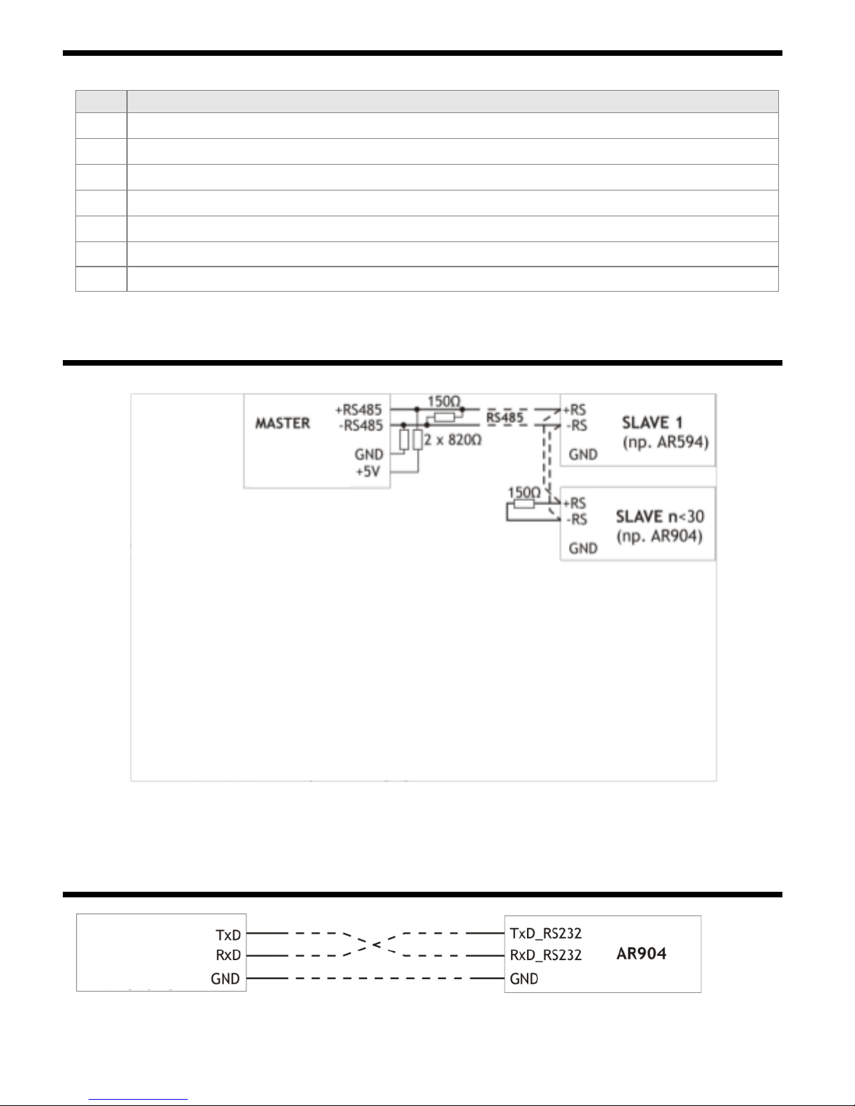
13. COMMUNICATION INTERFACE RS485 (in accordance with EIA RS-485)................ 10
14. COMMUNICATION INTERFACE RS232C (in accordance with EIA RS-232C) ........... 10
15. MODBUS - RTU SERIAL COMMUNICATION PROTOCOL........................................... 11
16. NOTES.................................................................................................................... 12
Particular attention shall be paid to the texts bearing this symbol
The manufacturer reserves the right to make changes in the design and software of the device without decreasing its technical parameters.
!

3
!
!
1. SAFETY RULES
Before using the device, please carefully read this instruction manual.
in order to avoid electric shock or damage to the device, mechanical
and electrical installation shall be carried out by qualified personnel
before turning on the power supply, make sure that all cables are connected correctly
before making any modifications to the wiring connections, turn off the power supply
to the device
ensure proper working conditions in accordance with the technical data of the device (power supply
voltage,
humidity, temperature, chapter 5)
2. INSTALLATION GUIDELINES
The device is designed to provide an adequate level of resistance to most disturbances that may occur in
the industrial environment. In environments with unknown levels of interference, the following
preventive measures are recommended to prevent possible interference with the device:
Do not operate the unit from the same lines as high-power units without using appropriate
network filters
use shielding of power and signal cables, whereby the screen should be grounded
single-point, as close to the device as possible
avoid routing the signal cables in the immediate vicinity of and parallel to
power cables
it is advisable to twist the signal cables in pairs
avoid proximity to remote-controlled equipment, electromagnetic meters, high-power loads
phase-controlled or grouped loads and other equipment which generates
high impulse disturbances
ground or reset the metal rails on which the rail-mounted devices are installed
Remove the protective foil from the LED display screen before starting to operate the unit.
3. GENERAL CHARACTERISTICS OF THE PROGRAMMING DEVICE
The device enables controlling or testing devices with current or voltage input.
(proportional valves, actuators, inverters, motors, etc.)
2 analogue outputs (simultaneous operation):
- current 4÷20mA or 0÷20mA (active, cannot be supplied in a two-wire current loop)
voltage from 0÷10V
soft start/stop (ramp) or triangular wave generator manually or automatically triggered when power
is applied.
programmable setpoint, output signal step change, display range, initial setpoint after power supply
start, soft start/stop, communication, access and other configuration parameters
7-segment LED display with brightness control
optional RS485/RS232 serial interface (galvanically isolated, MODBUS-RTU protocol)
parameter configuration methods:
- using an IP65 foil keypad located on the front panel of the device
- using an AR955 programmer or the RS485/RS232 interface and a free computer program
ARSOFT- WZ1 (Windows 2000/XP/Vista/7/8)
software and programmer which allow to preview the setpoint and quickly configure individual or
predefined sets of parameters previously saved on a PC for re-use, for example for other referencing
units of the same type (configuration duplication), access to configuration parameters is protected

4
by a user password.
High accuracy and immunity to interference
available accessories:
- programmer AR955
- RS485 to USB converter
CAUTION:
Before commencing operation of the programming device, please read this instruction manual
and correctly perform electrical and mechanical installation and configuration of parameters.
4. CONTENTS OF THE KIT
programming device
Instruction manual
warranty card
5. TECHNICAL SPECIFICATIONS
Number of analogue outputs
2
- current(active)
standard
0/4÷20mA (1)
- full range of changes
3.8÷21mA / 0÷21mA / 21÷3.8mA / 21÷0mA
- load resistance
R0≤ 1 kΩ
- resolution (maximum)
1,7 μA
- voltage in
standard 0/2÷10V
- full range of changes
0÷10.5V / 10.5÷0V
- load resistance
R0> 2.3 kΩ (load current I0< 4.5mA)
- resolution (maximum)
0.84 mV
Processing errors(at ambient temperature 25°C):
- basic
0.1 % of full output range ±1 digit
- additional for ambient temperature changes
< 0,005 % inut range /°C
Output response time(10÷90%)
200 ms
RS485
Communication
interface
- protocol
MODBUS-RTU
- speed
2.4 ÷ 38.4 kb/s
- symbol format
8N1 (without parity bit, 1 stop bit)
- galvanic separation
500V, 50Hz, 1min
Display
7-segment LED
(1 line, 4 digits)
- height and colour
20mm, red (adjustable brightness)
- range of indications
-1999 ÷ 9999, programmable
- decimal point position
Programmable, 0 ÷ 0.000
Power supply
- 230Vac
85 ÷ 260 Vac/ 4VA
- 24Vac/dc (optional)
20 ÷ 50 Vac/ 4VA, 20 ÷ 72 Vdc/ 4W
Nominal conditions of use
0 ÷ 50°C, <90 %RH (w/ out condensation)
Working conditions
air and neutral gases
Protection level
IP65 from the front panel, IP20 from the
connectors side
Weight
~160g
Electromagnetic compatibility (EMC)
resistance: according to EN 61000-6-2 standard
emissivity: according to the standard PN-EN 61000-6-
4
(1) the output cannot be powered by a two-wire current loop
!

5
72
717
45
poliwęglan
NORYL
WIDOK OD STRONY
UCHWYTU MOCUJĄCEGO
6. ENCLOSURE MEASUREMENTS AND INSTALLATION DATA
Type of enclosure
array, Incabox XT L57
Materiał
self-extinguishing NORYL 94V-0,
polycarbonate
Dimensions of the
enclosure
96 x 48 x 79 mm
Array window
92 x 46 mm
Attachment
handles on the side of the enclosure
7. DESCRIPTION OF TERMINALS AND ELECTRICAL CONNECTIONS
Terminals
Description
1-2
current output 0/4÷20mA
3-4
voltage output 0÷10V
5-6-7
RS485/RS232 serial interface (MODBUS-RTU transmission protocol)
8-9
230Vac or 24Vac/dc power input
PRG
programming interface compatible with the AR955 programmer (do not use
simultaneously with the RS485/RS232 interface)
a) numbering of connectors and signal output methods
CAUTION:
Connecting devices other than the AR955 programmer to the PRG socket may damage
the connected device and the AR904 programming device
8. BUTTON FUNCTIONS
7-segment LED display
programming buttons
!
polycarbonate
VIEW FROM THE SIDE OF
MOUNTING HANDLE

6
a) button functions in setpoint display mode (normal mode)
Button
Description[and the corresponding symbol in the manual].
[UP] or [DOWN]:
Increase or decrease the setpoint of the output signal by the set
change value ( parameter 6:, chapter 10 )
[SET] + [UP]:
- incremental (extreme) change of the setpoint value of the output signal -
highest
value of the indication range (parameter 3:) or limiting the setting (5:)
[SET] + [DOWN]:
- incremental (extreme) change of the setpoint value of the output signal - lowest
value of the indication range (parameter 2:) or limiting the setting (4:)
[UP] and [DOWN] (simultaneously): entering the parameter configuration menu
(hold pressed for more than 1 sec.) If parameter 13:=(password protection
is enabled) enter the password (chapter 10)
[SET]
Start/stop the soft start/stop function
(hold pressed for more than 1.5 seconds). If parameter 8: and 9: =
the function is inactive (chapter 11)
(b) button functions in the parameter configuration menu (Chapter 10)
Button
Description
[SET]
- editing the current parameter
- confirm and save the edited parameter value
[UP] or [DOWN]:
- move to the next or previous parameter name
- change the value of the edited parameter
[UP] and [DOWN] (simultaneously):
- cancelling changes in the edited value (return to parameter name)
Return to the setpoint display mode (hold pressed for > 0.5s).
9. CHANGING THE OUTPUT SETPOINT
Pressing the [UP] or [DOWN] button in the setpoint value display mode causes to change the value by a
step (parameter 6:, chapter 10, Table 10). Changes in the output signal are proportional to the
changes in the displayed value. Using a combination of buttons[SET]+[DOWN] instantly sets the output
level to the lowest possible value (2: or 4:) while [SET]+[UP] sets it to the highest possible value
(3: or 5:). In addition, the output signal can be also set in the parameter programming mode
(parameter 7:) and via the serial interface RS485/RS232 or AR955 programmer (Chapter 15, Table 15).
Additionally, it is possible to set the value to a level which exceeds the range of parameters 2: and
3:. The value of the overdrive for buttons is ±5% for the 4÷20mA (2÷10V) output and +6.2% for the
remaining outputs.

7
10. SETTING CONFIGURATION PARAMETERS
All configuration parameters of the device are contained in EEPROM internal memory.
There are two ways to configure the parameters:
1. With IP65 foil keypad on the front panel of the device:
- enter the configuration menu from the setpoint display mode (by simultaneously pressing
[UP] and [DOWN] for a time greater than 1 sec.) If parameter 13: = (password protection
is
on) the following message will appear on the display, followed by with the first digit
blinking, using the [UP] or [DOWN] button, enter the access password (by default, parameter
12: = ), moving across positions and entering the code can be done with the [SET]
button.
- after entering the configuration menu, the mnemonic names of the parameters are displayed
( <->
<-> <-> itd. ), pressing the [UP] button allows to move to the next parameter, while
pressing the [DOWN] button moves to
the previous parameter (for a consolidated list of configuration parameters, see Table 10)
- in order to change or preview the value of the current parameter press the [SET] button
- by pressing [UP] or[DOWN] you can change the value of the edited parameter
- the modified value of a parameter can be confirmed by pressing the [SET] button or cancelled by
pressing [UP] and [DOWN]
(simultaneously), which will in turn display the name of the parameter
2. Via RS485/RS232 portor the AR955 programming set and the ARSOFT-WZ1 computer software:
- connect the referencing-unit to the computer port and start the ARSOFT-WZ1 application
- after the connection has been established, the current setpoint is displayed in the program
window.
- setting and previewing the parameters of the device is available in the parameter configuration
window.
the new parameter values must be confirmed by pressing Approve changes
- the current configuration can be saved to a file, values can be also loaded from a file
CAUTION:
!
Do not use both the RS485/RS232 port and the AR955 programming set at the same time, because
this will cause communication errors.
To restore the factory settings when turning the device on simultaneously press[UP]and [DOWN] buttons
until the password entry menu appears (), and then enter the code . Alternatively, you can use
the default configuration file in ARSOFT-WZ1.
Table 10. Configuration parameters
Parameter
Range of parameter variation and description
Factory
settings
0:
type of current and
voltage output
standard 4..20 mA (0..10V)
standard 0..20 mA (0..10V)
1:
dot position
no dot
(0.0)

8
2:
the bottom of the
display range
÷ units - display for 0mA, 4mA, 0V - beginning of output
scale
3:
upper range of
indications
÷ units - display for 20mA, 10V - end of output scale
4:
set lower limit
÷ units, lower setpoint limit
(Parameter 7:) when setting up using the buttons on the device
5:
upper limit
÷ units, upper setpoint limit
(Parameter 7:) when setting up using the buttons on the device
6:
step change
÷ units, step change for the setpoint (parameter 7:) when
setting up using the buttons on the device
7:
setpoint
Lower limit: parameter 2: or 4:, upper limit: parameter
3: or 5:, change step: 6:, when setting up using the
buttons on the device
8:
soft start time
÷ s
the duration of the rising slope (ramp), for the value
offunction switched off, description in chapter 11
deactivated
9:
soft stop time
÷ s
duration of descending slope (ramp), for values
function switched off, description in chapter 11
deactivated
10:
ramp release mode
automatic
soft start/stop (ramp) trigger after each power-on
(chapter 11)
Manual
operation
manual
soft start/stop (ramp) triggering by means of a manual
push-button[SET](Chapter 11)
11:
Setpoint setting lock
deactivated
setpoint change inhibition disabled by pushbuttons
deactivated
activated
button lock activated
12: access password
÷
password for accessing the setup menu
13: password
protected configuration
access to configuration menu is not password-
protected
deactivated
Entering the configuration menu is protected by an
access password.
14: display
brightness
÷ %, change by 10%
%
15:
MODBUS-RTU address
÷
the individual address of the device in the RS485
network
(chapter 13) or for the AR955 programming unit
16: RS485/232 or
AR955 programmer
transmission speed
kbit/s
kbit/s
kbit/s
kbit/s
kbit /s
kbit/s
17: start setpoint
(7: ) after powering
on (1)
last stored setpoint (7:)
range start (2:) or set lower limit (4:)
range end (3:) or set upper limit (5:)
Remarks: (1) – parameter available since version (device firmware can visible after powering on)

9
11. SOFT START/STOP AND TRIANGLE WAVE GENERATOR
The device is equipped with the function of a ramp (soft start and stop) operating according to the
diagrams below (Figures 11.1, 11.2, 11.3). In order to start the function, the soft start time (ascending
slope, parameter 8) must be configured:Chapter 10) or of the soft stop (falling slope, 9:) and
the method of triggering (triggering, 10: ). If both times are non-zero (8:and 9: ) a
periodical triangle wave is generated at the outputs. The limit values (amplitudes) of the output signals
are defined by the following parameters 2:, 3:, 4: and 5:.
This function is activated automatically after the power supply is switched on (when parameter 10:
= ) or manually (10: = ) with the [SET] button (hold pressed for longer than 1.5 sec). In
addition, the ramp can be stopped and restarted at any time by pressing the [SET]button (a momentary
message appears for start or - for stop).
Output status in this mode is automatically updated 4 times per second.
Fig.11.1 Principle of operation of outputs in the soft start mode (parameter > 0, = ).
Fig.11.2 Principle of operation of outputs in the soft stop mode (parameter = , > 0).
Fig.11.3 Zasada działania outputs in the triangle wave generator mode (parameter > 0, > 0).
set value
or
or
or
or
automatic or manual start
using the [SET] button
automatic setting (ramp)
manual setting
output signal
time
set value
set value
automatic or manual start
using the [SET] button
automatic or manual start
using the [SET] button
automatic setting (ramp)
manual setting
manual setting
output signal
output signal
time
time

10
12. MESSAGES AND ERRORS
The following instantaneous messages may appear while the unit is operating:
Code
Message description
Entering the password mode for accessing configuration parameters (chapter 10).
an incorrect password has been entered
Entering the parameter configuration menu.
setpoint setting lock on (11: = , Chapter 10)
Setpoints lock due to activating ramp function (Chapter 11)
Manual starting of the soft start or stop function ( [SET] button)
Manual stopping of the soft start or stop function ( [SET] button)
13. COMMUNICATION INTERFACE RS485 (in accordance with EIA RS-485)
Devices of different manufacturers that form RS485 network (e.g. RS485/USB converters) can have built-
in polarizing and terminating resistors, and then there is no need to use external elements.
14. COMMUNICATION INTERFACE RS232C (in accordance with EIA RS-232C)
master device,
e.g. computer
Max. length of RS485 cord –1 km.
Max number of devices in RS485 line –30, in order to increase the
number of devices, use RS485/RS485 amplifiers.
Terminating resistors when MASTER is at the start of the line (fig.
above):
-At the start of the line –2 x 820Ω to GND and
MASTER +5V and 150 Ω between the lines,
-At the end of the line –150 Ω between the lines
Terminating resistors when MASTER is in the middle of the line:
-By the converter –2 x 820 Ω, to GND and +5V
converter,
-On both ends of the line - 150 Ω between each of the
lines
COMPUTER or
RS232C DRIVER
Maximum cable length –10 m.
Maximum number of devices connected to a computer –1.

11
15. SERIAL TRANSMISSION PROTOCOL MODBUS – RTU
Character Format: 8 bits, 1 stop bit, without parity
Available functions: READ - 3 or 4, WRITE - 6
Table 15.1. Frame format request for READ function (frame length - 8 bytes):
device
address
function
4 or 3
Registry address to be
read: 0 ÷ 23 (0x0017)
number of registers to be
read: 1 24 (0x0018)
CRC checksum
1 byte
1 byte
2 bytes (HB-LB)
2 bytes (HB-LB)
2 bytes (LB-HB)
Example 15.1. Registry readout with address 0: 0x01 - 0x04 - 0x0000 - 0x0001 - 0x31CA
Table 15.2. Frame format request for WRITE function(Frame length - 8 Bytes):
device
address
function 6
registry address for
recording: 0 ÷ 23
(0x0017)
value of the registry to be
recorded
CRC checksum
1 byte
1 byte
2 bytes (HB-LB)
2 bytes (HB-LB)
2 bytes (LB-HB)
Example 15.2. Saving registry with address 10 (0xA) with value 0: 0x01 - 0x06 - 0x000A - 0x0000 -
0xA9C8
Table 15.3. Frame format for READ output (minimum frame length - 7 bytes):
device
address
function
4 or 3
number of bytes in the
data field, (maximum
24*2=48 bytes)
data field - value of the
register
CRC checksum
1 byte
1 byte
1 byte
2 ÷ 48 bytes (HB-LB)
2 bytes (LB-HB)
Example 15.3. The response frame for a registry value of 0: 0x01 - 0x04 - 0x02 - 0x0000 - 0xB930
Table 15.4. Frame format for WRITE output (frame length - 8 bytes):
a copy of the request frame for the WRITE function (Table 15.2)
Table 15.5. The specific answer is (Errors: field function = 0x84 or 0x83 when READ function was
performed and 0x86 when WRITE function was performed):
Error code (HB-LB in the data
field)
Error description
0x0001
non-existent registry address
0x0002
incorrect value of registry to be saved
0x0003
Incorrect function number
Example 15.5. Error frame for a non-existent readable registry address:
0x01 - 0x84 - 0x02 - 0x0001 –0x5130
Table 15.6. Map of registers for the MODBUS-RTU protocol
Registry
address
hex (dec)
Value
DEC
Register description and type of access
(Read-only R-register, read-only R/W-write-only)
0x00 (0)
-1999 ÷ 9999
current setpoint (register in RAM)
R/W
0x01 (1)
904
device type identifier
R
0x02 (2)
20 ÷ 99
firmware version of the recorder
R
0x03 ÷ 0x05
0
not used or reserved
R

12
0x06 (6)
0 ÷ 1
Parameter 0: output type (Chapter 10, Table 10)
R/W
0x07 (7)
0 ÷ 3
Parameter 1: decimal point position
R/W
0x08 (8)
-1999 ÷ 9999
Parameter 2: lower range of indications
R/W
0x09 (9)
-1999 ÷ 9999
Parameter 3: upper range of indications
R/W
0x0A (10)
-1999 ÷ 9999
Parameter 4: lower adjustment limit
R/W
0x0B (11)
-1999 ÷ 9999
Parameter 5: upper adjustment limit
R/W
0x0C (12)
1 ÷ 5000
Parameter 6: change step
R/W
0x0D (13)
-1999 ÷ 9999
Parameter 7: setpoint
R/W
0x0E (14)
0 ÷ 8160
Parameter 8: soft start time
R/W
0x0F (15)
0 ÷ 8160
Parameter 9: soft stop time
R/W
0x10 (16)
0 ÷ 1
Parameter 10: ramp release mode
R/W
0x11 (17)
0 ÷ 1
Parameter 11: setpoint setting lock
R/W
0x12 (18)
0 ÷ 9999
Parameter 12: password
R/W
0x13 (19)
0 ÷ 1
Parameter 13: password data protection
R/W
0x14 (20)
10 ÷ 100
Parameter 14: display brightness
R/W
0x15 (21)
1 ÷ 247
Parameter 15: MODBUS-RTU address
R/W
0x16 (22)
0 ÷ 4
Parameter 16: data transfer speed for RS485/RS232 or the AR955
programmer
R/W
0x17 (23)
0 ÷ 2
Parameter 17: the initial setpoint after the power supply has
started
R/W
16. NOTES
Table of contents
Other APAR Test Equipment manuals