OPERATION / MAINTENANCE MANUAL
7032SOUTH196th-KENT,WA.98032-(253)872-0141/FAX(253)872-8710
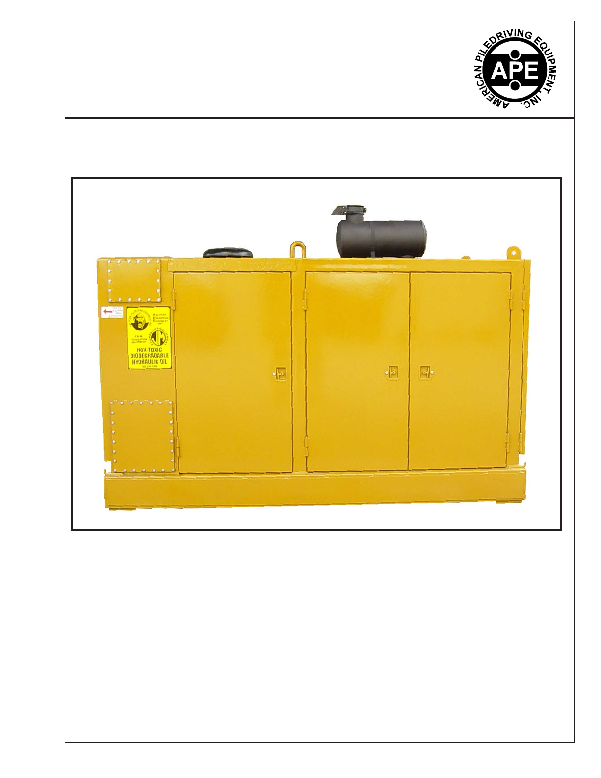
MODEL475POWERUNIT
VII. MODEL 475 POWER UNIT
VII-1.HydraulicCircuitry.
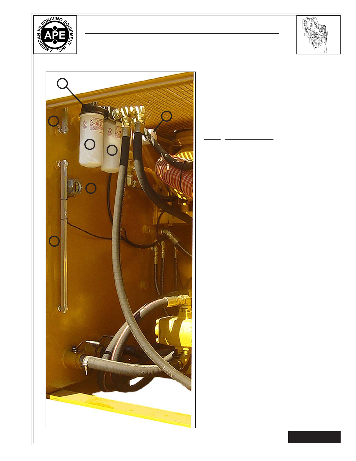
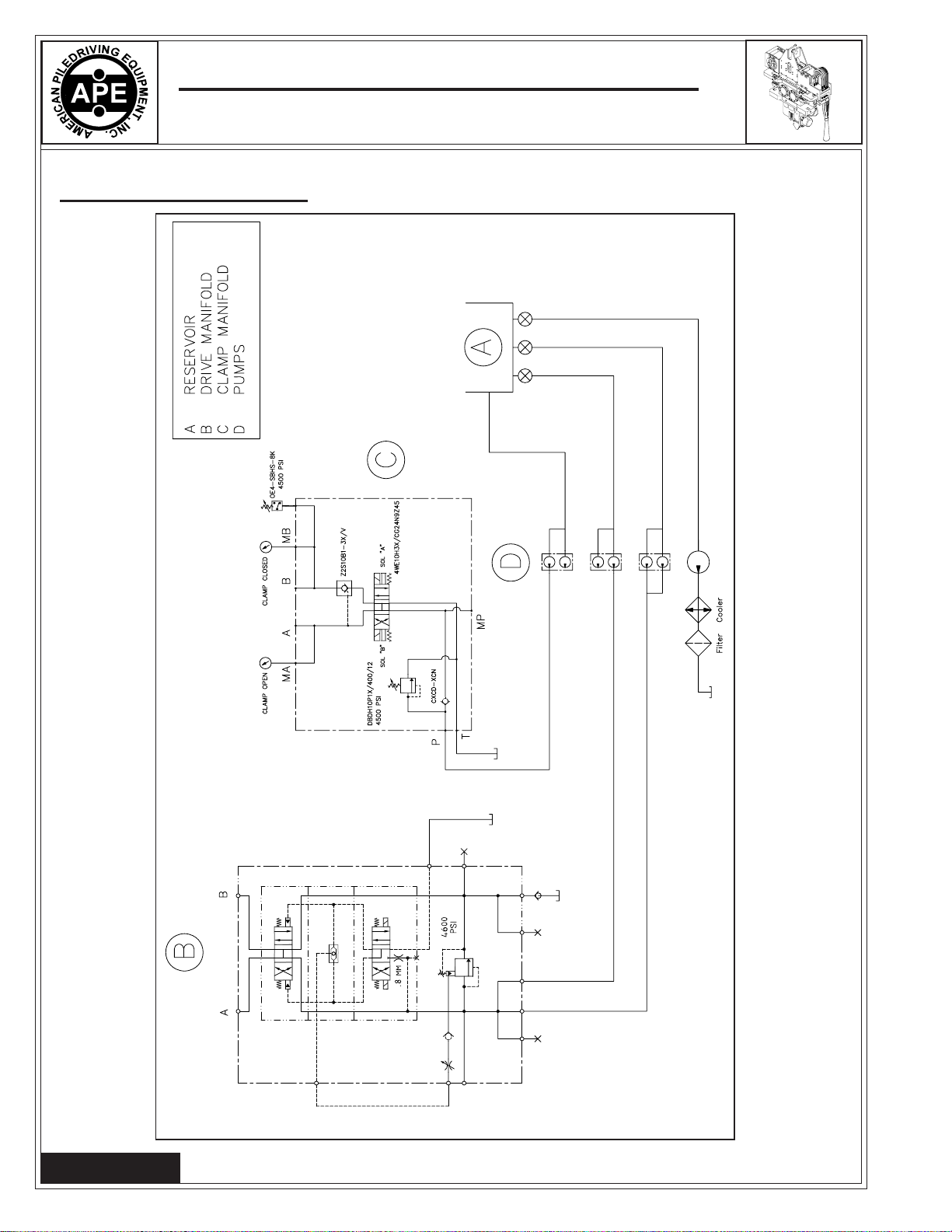
ThefollowingaredescriptionsofthecomponentsthatmakeuptheHydraulicCircuitryoftheAPEModel
475powerunit.
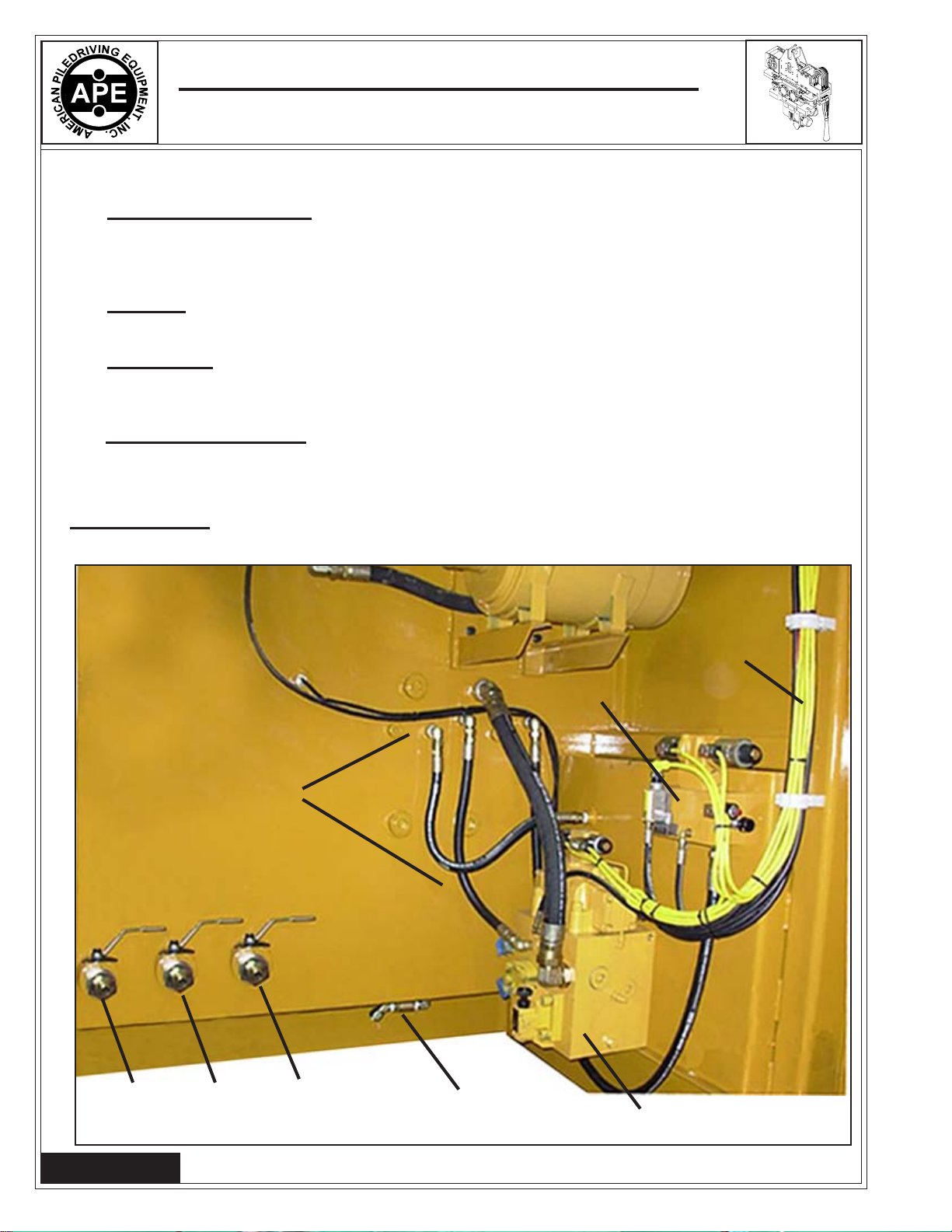
VII-1A.ClampCircuitry.(Usedforextendingandretractingjawcylinder)
Oilfortheclampcircuitisprovidedbyitemtheclamppump.Thispumpisal.5cu.in/rev5000psipiston
pump. Alloiltotheinletofthispumpisfilteredthroughasuctionstrainerlocatedinthetank. Clampoil
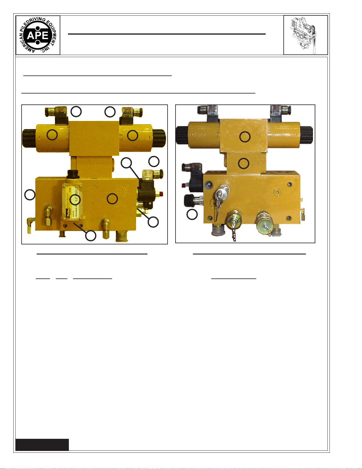
isthendirectedfromthepumptotheclampdirectionalcontrolvalve. Whentheclampswitchisinthe
"off"position,theoilflowsthoughttheclampdirectionalcontrolvalveandbacktotheoiltank. When
theclampswitchismovedtoopen,solenoid"A"ontheclampdirectionalcontrolvalveisenergizedthe
oilwillflowouttotheclampcylinderandretractoropenthejaws. Theclampopenpressurecanbeseen
on the clamp pressure gage located on the panel. When the clamp switch is moved to the closed
position,solenoid"B" willbeenergizedand oilflowwillbe directedtotheclamp cylinder. Theclamp
cylinderwillthenextendorclosethejaws. AClamppressure switchitemwillde-energizesolenoid"B",
directing pump oil flow back to oil tank. Clamp pressure is maintained in clamp cylinder by a pilot
operatedcheckvalve.Atanytimeshouldtheclamppressurefallbelow3500psi.theclamppressure
switch will re-energize solenoid "B" on the clamp control valve, and direct pump flow to the clamp
cylinder.Maximumclamp pressureislimitedby theclamppressurerelief valvesetat4300 psi. The
quickdisconnectcouplerspermitdecouplingofclamphoses.
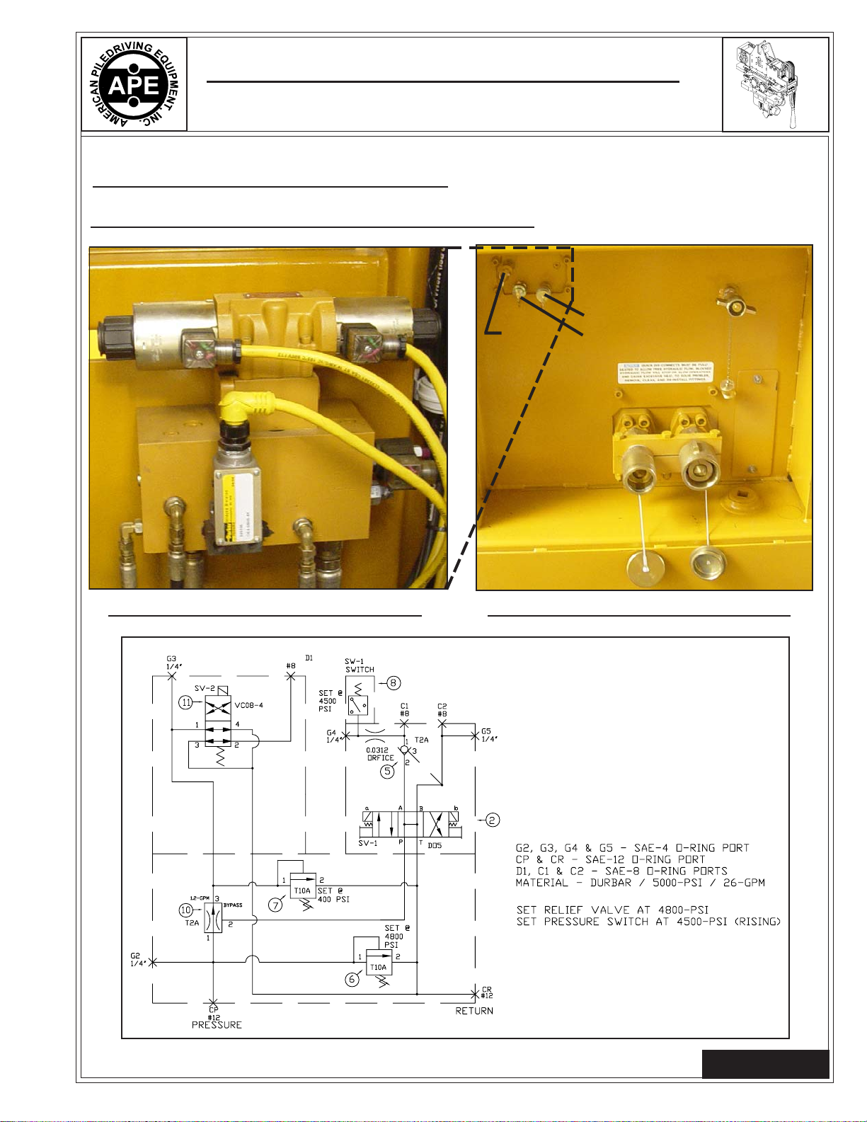
VII-1B. Drive Circuit. (UsedforoperatingAPEvibrator,APE drill or any otherunit)
Therearetwogearpumpsthatdirectoiltothedrivecircuit(VibroMotors).Themaximumdrivepressure
iscontrolledbythedrivepressurereliefvalve,to4800psi.max.Whenthedriveswitchismovedtothe
forwardposition,solenoid"A"ofthedrivedirectionalcontrolvalveisenergized.Oilflowisdirectedto
thevibromotorstorotatetheeccentrics.Whenthedriveswitchismovedtotheoffposition,oilflowis
directedbacktothetankthroughthedrivedirectionalcontrolvalveandsolenoid"A"isde-energized.
Becauseofthehighoilflowinthedrivecircuit,APE,Inc.hasdevelopedacircuitthateliminateshigh
shockloads. Smallinternalcomponentslocatedinthedrivemanifoldprovideasoftshiftfeatureforthe
drivedirectionalcontrolvalve. A smalladjustablesnubbervalvecontrolsasmallshuttlevalvethrough
smallfixedorifices. Theorificesareusedtodampentheshiftingof spoolvalve. Thisprovides asoft
start/stopofthedrivedirectionalcontrolvalvepreventinghydraulicshocktothedrivesystem. Theshuttle
valveisusedtosendahydraulicsignaltothedrivepressurereliefvalvewhenthedrivedirectionalcontrol
valveiscenteredorde-energized.Thishydraulicsignaltellsthedrivepressurecontrolvalvetoopenand
allowanyhighflow,highpressurebacktotank. Thesnubbervalvesimplycontrolshowfastthissignal
isreceivedbythedrivepressurereliefvalve.Thedrivepressurecanbereadonthedrivepressuregage
item.
Thequick-disconnectcouplings permitde-couplingofthedriveandcasedrainhosesatthepowerunit.
Page 7-1
Page 7-1
Copyright © 2023 American Piledriving Equipment, Inc. All Rights Reserved