Apeks 2000PSI THE DUPLEX User manual

Updated 08/28/2018 ©Apeks, LLC 2014
2000PSI THE DUPLEX™
BOTANICAL OIL EXTRACTION SYSTEM
OPERATION MANUAL
WARNING
FAILURE TO FOLLOW THE SETUP AND OPERATION PROCEDURE
PROVIDED IN WITHIN THIS MANUAL MAY VOID THE EXTRACTION
SYSTEM’S WARRANTY
Apeks LLC
150 Commerce Blvd.
Johnstown OH 43031
740-809-1160
www.apekssupercritical.com
Scan this QR code to get the
most recent version of the
operating instructions.

Apeks Supercritical The Duplex™ Operation Manual
2
Revision Date 8/28/2018
Table of Contents
Content
1. Critical Safety Overview
2. System Overview
2.1. Diaphragm System Overview
2.1.1. Diaphragm Compressor
2.1.2. Extractor Vessel Stand
2.1.3. Separation Vessel/Control Stand
2.1.4. Bottle Connections
2.1.5. Extractor Chiller/Temperature Control Chiller
2.1.6. Separator Chiller/Regenerative Chiller
2.1.7. Miscellaneous/Multi-Area Parts
2.2. Automation Overview
2.2.1. Logo Screen
2.2.2. Home/Main Screen
2.2.3. Cycle Parameter Screen
2.2.4. Valve Control Screen
2.2.5. Manual Screen
2.2.6. Maintenance Screen
2.2.7. Message Screen
2.2.8. Code Entry Screen
2.2.9. I/O Screens
2.2.10. Alarm History Screen
2.2.11. Popup Screens
2.3. Running Modes
2.3.1. Single Extractor
2.3.2. Dual Extractor
2.3.3. Continuous Batch
2.4. Manual Screen Buttons
2.4.1. Service Separator Mode
2.4.2. Change CO2Bottles
2.4.3. Oil Pressure Lost Reset
2.4.4. Diaphragm Rupture Reset
2.4.5. Evacuate
2.4.6. Open Extractor Vessel
2.4.7. Recover CO2
2.4.8. Water Flow Lost Reset
2.4.9. Switch Separators
2.4.10. Start/Stop Extractor Chiller
2.4.11. Start/Stop Separator Chiller
2.4.12. Lamp Test
2.4.13. Start/Stop Compressor Prime
2.4.14. Fill Separator Bank 2 Water
3. System Operation
3.1. Before the Cycle
3.1.1. Loading and Closing Extractors
3.1.2. Prepping and Securing Separators
3.1.3. Evacuating System
3.2. Starting the Cycle
3.2.1. The Cycle Parameter Screen
3.2.2. The Main Screen
Page#
5
6
7
7
8
9
11
11
11
12
12
12
13
13
14
14
15
15
16
19
19
21
21
21
22
22
22
22
22
22
22
22
22
22
22
22
22
22
22
22
22
23
23
23
24
24
24
24
25

Apeks Supercritical The Duplex™ Operation Manual
3
Revision Date 8/28/2018
3.2.3. System Response on Startup
3.3. Recommended Operating Parameters
3.3.1. Subcritical
3.3.2. Supercritical
3.4. During the Cycle
3.4.1. Service Separator/Cleaning out Separator that is offline
3.4.2. Cleaning Out Extractor in Continuous Batch Mode
3.4.3. Changing Bottles
3.5. After the Cycle
3.5.1. System Response on Shutdown
3.5.2. Operator Maintenance
4. System Preventive Maintenance
4.1. Extraction System Maintenance (Extractor and Separator Stands)
4.2. Diaphragm Compressor Maintenance
4.3. Chiller Maintenance
5. Troubleshooting
5.1. System Messages
5.1.1. Leak Detect Switch Tripped
5.1.2. E-stop Reset
5.1.3. Payment due by end of month
5.1.4. Check orifice size. Elevated separator pressure detected.
5.1.5. Diaphragm pump pressure switch tripped
5.1.6. Monthly code entry required
5.1.7. Pump outlet pressure high.
5.1.8. Separator pressure has risen
5.1.9. Low bottle detected at Startup
5.1.10. Machine is in bottle change mode
5.1.11. Cycle complete or terminated but vessel(s) still pressurized
5.1.12. Recovery complete
5.1.13. Check/Replace Bottle.
5.1.14. Extractor Pressure > 2000psi twice in ten minutes
5.1.15. Extractor Pressure not equalizing
5.1.16. Recovering due to low system pressure
5.1.17. Recovery has begun
5.1.18. CO2Low bottle pressure
5.1.19. Transition to (BA/AB) but Ext (A/B) not ready
5.1.20. Sep pressure test failed
5.2. System Alarms
5.2.1. Air PSI High/Low Alarm
5.2.2. Chiller 1 Fault/Warning Alarm
5.2.3. Chiller 2 Fault/Warning Alarm
5.2.4. CO2 Storage PSI High/Low Alarm
5.2.5. CO2Supply PSI High/Low Alarm
5.2.6. Code Needed Alarm
5.2.7. Diaphragm Compressor Ambient Temperature Alarm
5.2.8. Diaphragm Compressor Outlet PSI High Alarm
5.2.9. Diaphragm Compressor Suction PSI High Alarm
5.2.10. Diaphragm Compressor Suction PSI Low Alarm
5.2.11. Diaphragm Rupture Shutdown Alarm
5.2.12. E-Stop Alarm
25
25
25
25
26
26
27
27
27
28
28
28
29
30
30
30
30
30
30
30
30
30
30
30
30
30
30
30
30
30
30
30
30
30
30
30
30
30
30
31
31
31
31
31
31
31
31
31

Apeks Supercritical The Duplex™ Operation Manual
4
Revision Date 8/28/2018
5.2.13. Extractor Not Equalizing Alarm
5.2.14. Extractor Water Flow Lost Alarm
5.2.15. Extractor Ambient Temperature Alarm
5.2.16. Extractor (Vessel A/B, Top/Bottom) PSI High Alarm.
5.2.17. Extractor (A/B) Vessel Temperature Alarm
5.2.18. Filter (1B/2B) PSI Drop Fault/Warning
5.2.19. Low System CO2Pressure
5.2.20. Oil Pressure Lost Alarm
5.2.21. Pressure Test Fail Alarm
5.2.22. Pump PSI High During Recovery Alarm
5.2.23. Pump Motor Auxiliary Fault Alarm
5.2.24. Pump Motor Overload Alarm
5.2.25. Separator Pressure Creep Alarm
5.2.26. Separator Water Flow Lost Alarm
5.2.27. Separator (1B/2B) Vessel PSI High Alarm
5.2.28. Separator (1B/2B) Vessel Temperature Alarm
5.2.29. Separator Ambient Temperature Alarm
5.2.30. Service Separator Mode Extractor PSI High Alarm
5.2.31. Valve Fault Alarm
5.3. Other Symptoms
5.3.1. Vessel not Pressurizing
5.3.2. High Extractor Pressure and Low Separator Pressure
5.3.3. High Separator Pressure and Low Extractor Pressure
6. References
Appendix A – Belt Tension Testing/Adjustment
Appendix B – Diaphragm Pump Priming
Appendix C – Check Valve Cleaning
Appendix D – Electrical Screw Torque Requirement
Appendix E – Piping and Instrumentation Diagram
Appendix F – CO2 Phase Diagram
31
31
31
31
31
31
31
31
32
32
32
32
32
32
32
32
32
32
32
32
32
32
32
32
33
34
35
36
39
40
43
Apeks Supercritical The Duplex™ Operation Manual
5
Revision Date 8/28/2018
1. Critical Safety Overview
Throughout these instructions, this symbol is used to indicate that the instructions are critically
important to your safety and the safety of your system. Failure to follow the instructions as written
can result in a rapid release of high pressure CO2potentially causing equipment or personnel
damage.
WARNING
Subcritical and Supercritical CO2systems operate under high pressure. Operators must be fully trained and
familiar with the system. Failure to operate the system can result in equipment damage and/or bodily injury.
WARNING
Subcritical and Supercritical CO2systems use large amounts of CO2during operation. Ensure that system is
installed in a well-ventilated area to prevent buildup of CO2which can cause asphyxiation. Use of a CO2monitor
is strongly recommended.
WARNING
Opening a vessel under pressure can result in a rapid release of pressure and ejection of the material inside the
vessel. DO NOT ATTEMPT TO OPEN A VESSEL UNDER PRESSURE! Always make sure a vent path for the
vessel is opened and the corresponding pressure gage reads zero prior to loosening the vessel hammer unions
or closure bolts.
WARNING
Subcritical and Supercritical CO2systems are designed to operate indoors. Extreme temperatures (below 60°F
and above 80°F) will negatively impact the functionality of the system. The environmental temperature range is
for the system, chiller, pump and CO2bottles.
WARNING
Only use Propylene Glycol and distilled water in the chiller and cooling system. Never use Deionized Water in
the chiller or cooling system.
WARNING
Always wear safety glasses when operating and servicing the system.
Apeks Supercritical The Duplex™ Operation Manual
6
Revision Date 8/28/2018
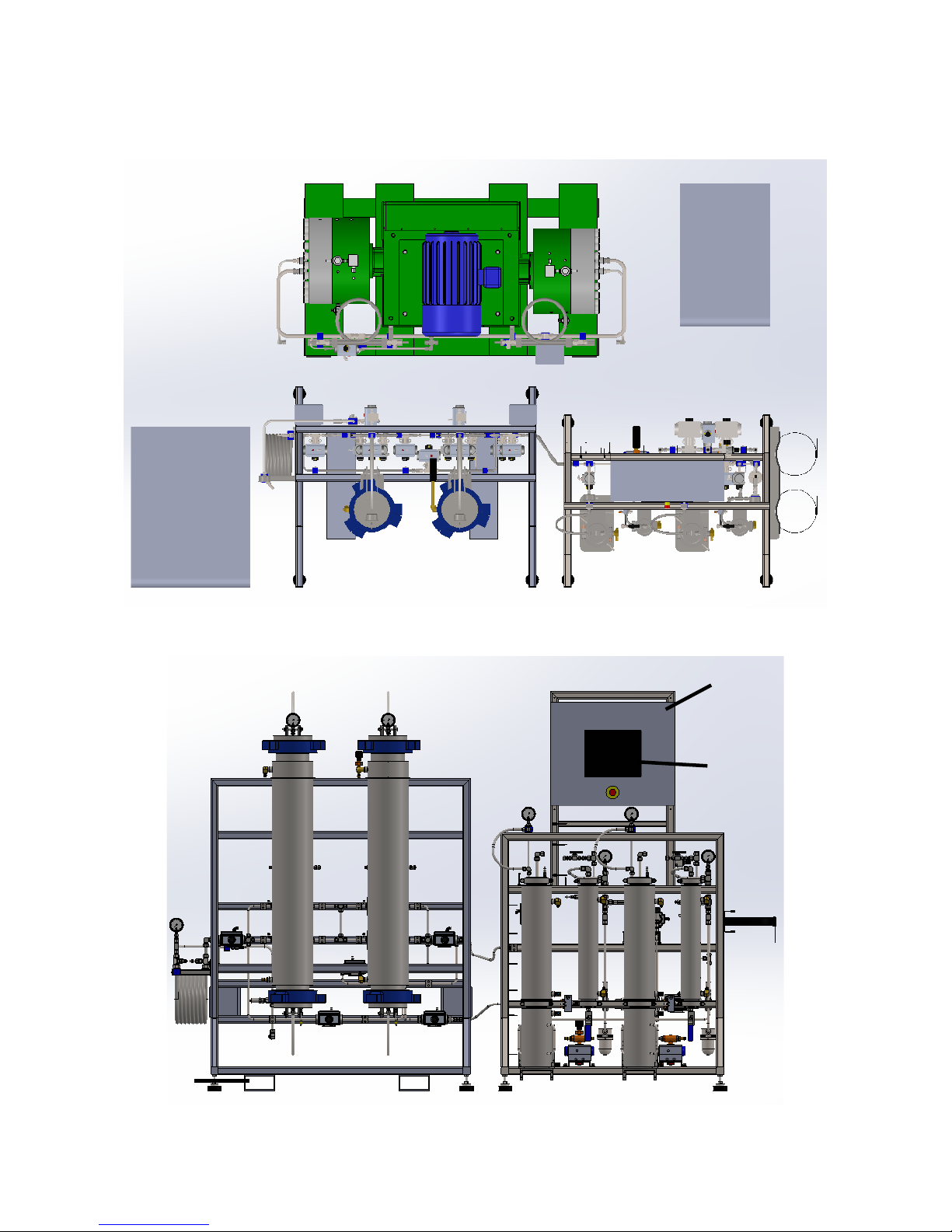
2. System Overview
The Duplex™ Diaphragm Compressor
Separator Chiller
Extractor Chiller
Extractor Vessel Stand
Separator Vessel Stand
Main Control
Enclosure
HMI
Fork Pockets

Apeks Supercritical The Duplex™ Operation Manual
7
Revision Date 8/28/2018
2.1.The Duplex™System Overview
2.1.1. Diaphragm Compressor – The diaphragm compressor for the Apeks 2000psi Duplex™ system
is dual head compressor where both heads work in parallel to compress CO2to the desired
target pressure in the extractors.
2.1.1.1. Gauges on the Compressor
2.1.1.1.1. Oil Pressure Gauges – There are two gauges that display different oil pressures on
the diaphragm compressor. The first is a high-pressure loop that incorporates the oil
heat exchanger and some internal bearings. This gauge should read between 40-50
psi at all times when the system is running. The second is a low-pressure loop that
incorporates the injection pump which supplies oil to the oil compression side of the
diaphragm head. This gauge should read between 15-20 psi when the system is
running.
2.1.1.1.2. Leak Detect Gauges – There is a leak detect switch on each pump head. This
gauge monitors the cavity between the oil side and CO2side to ensure that there is
no crossover between the two systems. This gauge should display no pressure. See
Troubleshooting section if this gauge shows pressure.
2.1.1.2. Pressure Switches
2.1.1.2.1. Oil Pressure Switch – The oil pressure switch monitors the low-pressure oil loop to
make sure there is oil flowing in the system. If oil pressure is lost this switch will stop
the system and an alarm will be triggered.
2.1.1.2.2. Leak Detect Pressure Switch – This pressure switch works the same as the leak
detect gauge but continually monitors for the presence of pressure and will shut the
machine down if over 15 psi of pressure detected in the pump cavity.
2.1.1.3. Over Pressure Valve (OPV) and Oil Bypass Valve – The OPV valve on the pump is a
back-pressure regulator. The valve is set to allow the hydraulic oil pressure in the head to
reach a certain point but not go above that point. The Bypass Valve is a needle valve with
CO
2
Outlet
CO
2
Inlet
Junction Box
Regenerative
Heat
Exchangers

Apeks Supercritical The Duplex™ Operation Manual
8
Revision Date 8/28/2018
a black handle that can be opened in order to bypass the OPV. This is done during
priming of the compressor and during head maintenance. (see appendix B)
2.1.1.4. Junction Box – The diaphragm compressor has a single junction box for the pressure
switches that has a Harding Connector (electrical quick-connect) and thermocouples that
go to the main control enclosure.
2.1.1.5. Regenerative Heat Exchangers – There are two regenerative heat exchangers that are
located on the pump, one for each diaphragm head. These heat exchangers remove heat
from the compressed CO2to use on the separators.
2.1.2. Extraction Vessel Stand
2.1.2.1. Extraction Vessels – There are two extraction vessels on each stand. Vessel A is
located on the right-hand side of the stand and Vessel B is located on the left. These
vessels can be either 5L or 20L and are Hammer Union Closure vessels. This closer
mechanism uses a nut to hold down a cap to allow the vessel to pressurize. Seals on this
vessel are cup style seals which expand with the presence of pressure and create a face
seal on the vessel. Extraction vessels are loaded and unloaded from the top of the
vessel. When loading, unloading and cleaning these vessels be sure to keep face surface
and threads clean. Failure to keep these surfaces clean can cause your vessel not to
seal properly and could cause damage to your cup seal.
2.1.2.2. Locking Vessel Isolation Valves – Each extractor has two locking isolation valves that
should be utilized whenever the operator is working in any vessel. These valves are
Extractor
A
Extractor
B
Flow Switch
Temperature
Control Heat
Exchanger

Apeks Supercritical The Duplex™ Operation Manual
9
Revision Date 8/28/2018
intended to valve off the inlet and outlet of the vessel to protect the user from any release
of pressure. WARNING: Failure to use these valves can lead to injury.
2.1.2.3. Temperature Control Heat Exchanger – The temperature control heat exchanger
regulates the temperature of the CO2just before it enters the extractor vessels and is in a
cooling loop along with the extractor vessel water jackets and the extractor flow switch.
2.1.2.4. Extractor Flow Switch –The flow switch continually monitors for water flow in the
extractor loop and will stop the system if flow is lost.
2.1.2.5. Vent Valves – Each extraction vessel has its own vent valve (Valve 4A and 4B) these
valves will open automatically to vent the extractor so they are safe to open. These
valves should be vented to the vent valve manifold (located on the Separator Stand) or
outside.
2.1.2.6. Pressure Gauges – Three gauges, Extractor A, Extractor B and Pump outlet (located on
top of temperature control heat exchanger), are located on the extractor stand and should
correlate to the pressures on the HMI for each portion.
2.1.2.7. Junction Boxes – Each extraction vessel has its own junction box which will have a
Harding Connector and at least one thermocouple connector that connects the main
control panel.
2.1.3. Separation Vessel/Control Stand
2.1.3.1. Separation Vessels – The Separator stand holds four separators that work in banks of
two. Bank 1 is located on the left-hand side of the stand and Bank 2 is located on the
Bank 1
Bank 2
E-Stop
Evacuation Valve
Vent Valve
Flow Switch
Collection Cup
Water Valves
Cup Lift
Control Panel Mount

Apeks Supercritical The Duplex™ Operation Manual
10
Revision Date 8/28/2018
right. Each bank contains a main separator with an oil collection cup and a secondary
separator with no cup. Users may use either set of separators at any time but only one
set at a time. Separator banks that have identical gauges, filters and manual valving.
2.1.3.2. Main Control Enclosure/HMI – Unless otherwise stated at time of purchase, the
separator stand will be where the main control enclosure and HMI (Human Machine
Interface) are located. This enclosure contains the logic controller that operates the entire
system. The HMI is located on the front of this enclosure and is where the user can
monitor and control the system.
2.1.3.3. Motor Starter Box – The motor starter box is located on the back of the separator stand
and houses the motor starter that controls the motor on the diaphragm compressor.
2.1.3.4. Air Valve Manifold – The Air valve manifold is located on the back of the separator
stand directly behind the Main Control Enclosure. This manifold controls the air to each
air actuated ball valve via red quarter inch airline.
2.1.3.5. Vent Manifold – This manifold collects all the vent lines to be vented outside by a single
line. It is located on back, very top of the control panel mount and has a ½” discharge line
up to 50 feet long.
2.1.3.6. Pressure Gauges – There are four pressure gauges located on the separator stand, two
for each set of separators. The gauge located behind the main separator (psi range of 0-
2000) is the inlet pressure for the separator and should match the pressure of the
extractors when the system is flowing. The second gauge is the pressure inside the
separators and should match the separator pressure on the HMI.
2.1.3.7. Separator Filters – Each separator bank has its own separator filter. These filters should
be inspected and cleaned between runs on the separator bank. See the preventive
maintenance section
2.1.3.8. Locking Vessel Isolation Valves – Each separator bank has two locking isolation
valves that should be utilized whenever the operator is working in any vessel. The bottle
connections have an isolation valve as well. These valves are intended to valve off the
inlet and outlet of the vessel bank to protect the user from any release of pressure.
WARNING: Failure to use these valves can lead to injury.
2.1.3.9. Vent Valves – Each separator bank has its own vent valve (Valve 10) that can be use to
release pressure from that bank of separators. These valves should be vented to the vent
valve manifold located above the air valve manifold.
2.1.3.10. Evacuation Valves A and B – Each separator bank has its own evacuation valve that
can be used to evacuate (draw a vacuum) the whole system before a run or evacuate the
individual separator banks while running. See Manual Screen on the HMI to evacuate the
entire system.
2.1.3.11. Separator Flow Switch – The flow switch continually monitors for water flow in the
separator loop and will stop the system if flow is lost.
2.1.3.12. E-Stop Button – The E-Stop (Emergency Stop) Button can be depressed by the user at
any time and will stop the system, turn off the pump, turns off the chillers and isolate
every vessel.
2.1.3.13. Cup Lifts – There is a lift below each separator vessel to assist in the disassembly and
the assembly of the separators and collection cups. This lift is air powered and actuated
with the black toggle handle located to the right of the lift. Toggling the handle up will
raise the cup lift and toggling the handle down will lower the cup lift. CAUTION: Use care
to keep appendages away from pinch points when using the cup lift.
2.1.3.14. Cup Lift Regulator – This regulator is factory set but can be adjusted to increase or
decrease the pressure to the cup lift piston.

Apeks Supercritical The Duplex™ Operation Manual
11
Revision Date 8/28/2018
2.1.4. Bottle Connections
2.1.4.1. Main Supply and Recovery Bottles – Three 75lb Gas Supply CO2bottles should be
used as the main bottles for The Duplex™ system. These bottles are connected to the
location shown above.
2.1.4.2. CO2Make-Up Supply Bottle – One 50 to 75lb Gas Supply CO2 bottle should be used
as a makeup bottle for CO2lost during and at the end of each cycle. This bottle is
connected to Valve 20 in the location shown above.
2.1.5. Extractor Chiller/Temperature Control Chiller – The Extractor Chiller is used to control the
temperature of the CO2before it passes over the raw material in the extraction vessel. Refer to
Installation Manual for chiller loop setup and chiller manual for more information on the chiller.
2.1.6. Separator Chiller/Regenerative Chiller – The Separator Chiller is used to control
temperatures of your CO2after compression or expansion. Refer to Installation Manual for
chiller loop setup and chiller manual for more information on the chiller.
2.1.7. Miscellaneous/Multi-Area Parts
2.1.7.1. Air Actuated Ball Valves – These ball valves are operated automatically by the
controller and the air valve manifold. Indicators on the front of the valve will display the
position of the valve. If the yellow line on the indicator is parallel to the valve body then
the valve is considered open. If the indicator is perpendicular then the valve is closed.
Valve positioning can be verified from the I/O Screen.
2.1.7.2. Relief Valves – Located throughout the system these valves mechanically protect the
system from over pressurizing.
Cup Lift Regulator
Main Supply and
Recovery Bottles
CO
2
Make-Up
Supply Bottle

Apeks Supercritical The Duplex™ Operation Manual
12
Revision Date 8/28/2018
2.2.Automation Overview
2.2.1. Logo Screen – This screen contains the software version information for your machine. You will
find the version in the lower left-hand corner of the screen. Contact Apeks with current version
information.
2.2.2. Home/Main Screen – This screen is the most common area to monitor the system during a
cycle. Key information such as temperatures, pressures and valve positioning can all be seen
on this screen as well as the cycle state. This screen is also how you will start the system and
contains the button to set the cycle parameters.
Apeks Supercritical The Duplex™ Operation Manual
13
Revision Date 8/28/2018
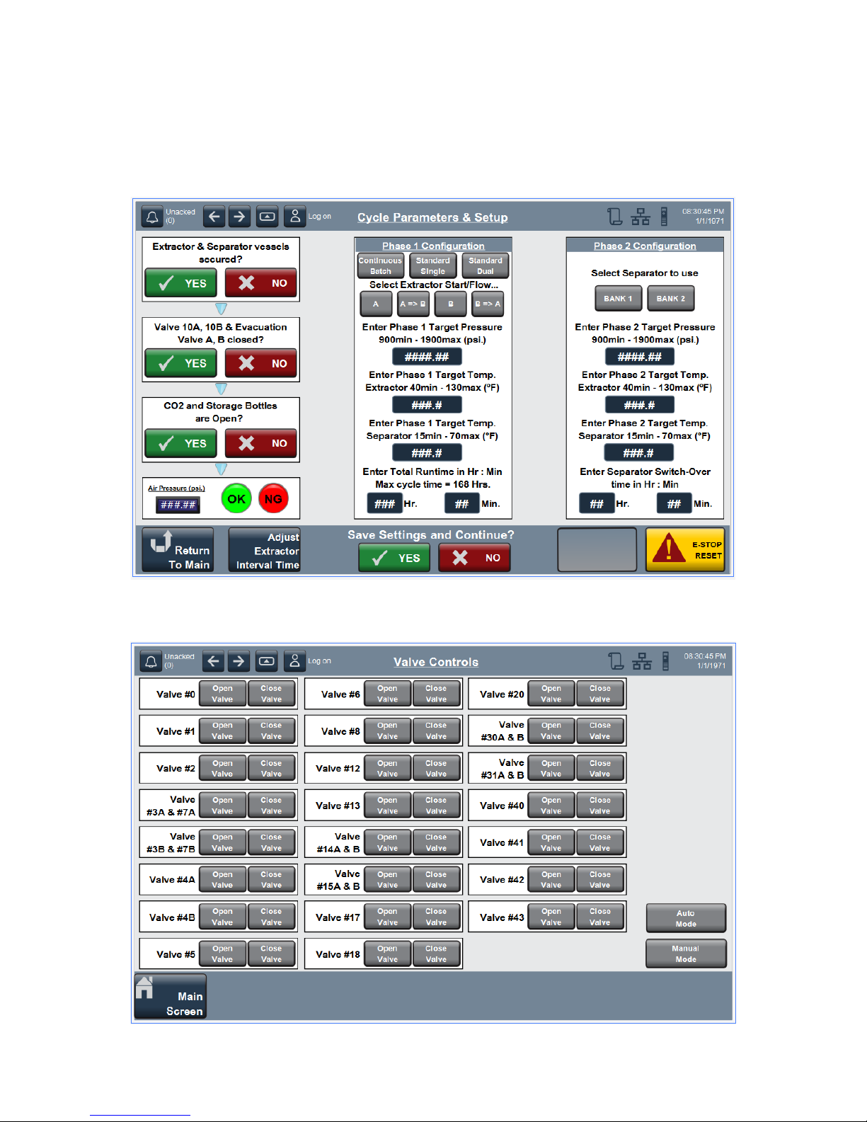
2.2.3. Cycle Parameters Screen – This screen is the place where the user will program how the
system will be ran. They will set target pressure and temperature, select run modes, set run
times and switch over times, and select which separator bank to start with. Many cycle
parameters such as times and temperatures can be adjusted during the run but run modes
(Single or Double Extractor or Continuous Batch) cannot be adjusted after the run begins.
2.2.4. Valve Control Screen – This screen is for Apeks use only and is locked from customer use.
Valve positioning can be seen on this screen. Current valve position will be highlighted.
Apeks Supercritical The Duplex™ Operation Manual
14
Revision Date 8/28/2018
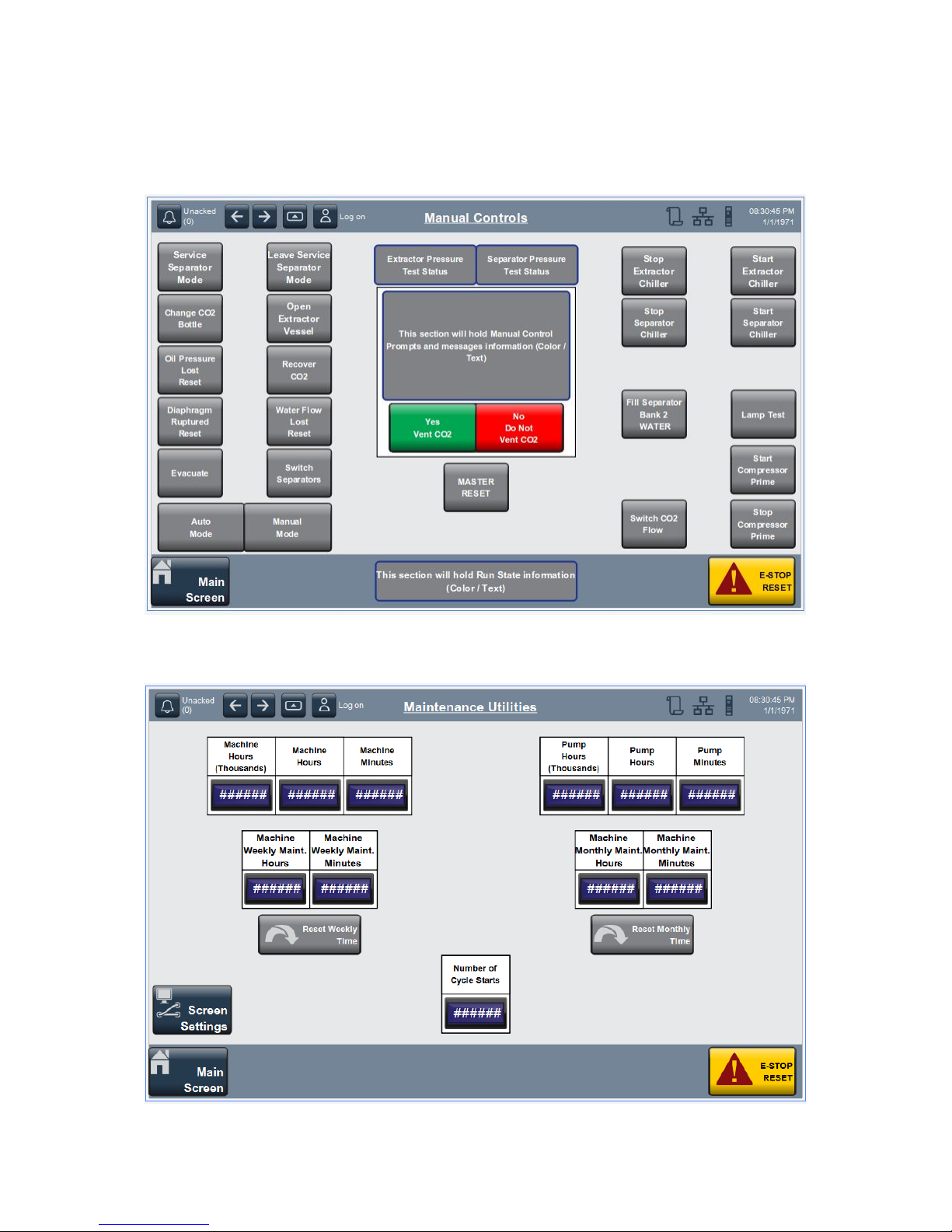
2.2.5. Manual Screen – Aside from the Main Screen this screen is the most common screen the
operator will interact with. The manual screen is where you will go to reset any alarms, service/
switch separators, change bottle and more. See Manual Screen Buttons Section for more
information.
2.2.6. Maintenance Screen – This screen is the timer screen for maintenance timers and total system
time. Maintenance timers can be reset but pump and machine time cannot.

Apeks Supercritical The Duplex™ Operation Manual
15
Revision Date 8/28/2018
2.2.7. Message Screen – This screen is where the operator will select which messages to receive
notifications about. This email messaging will require an initial setup which can be scheduled at
http://www.apekssupercritical.com/customer-support/service-request/ . Setup will require a
dedicated email address for the system. Messaging ability requires connection to the internet.
Data collection data and remote viewing will also be set up with this alerting service.
2.2.8. Code Entry Screen – This screen is used for systems that are leased. Leased systems will
require a monthly passcode to run.

Apeks Supercritical The Duplex™ Operation Manual
16
Revision Date 8/28/2018
2.2.9. I/O Screens– This screen is used for more precise system monitoring. The operator can
monitor every input and output of the Program Logic Controller (PLC) from these screens.
These screens are mainly used during troubleshooting.
2.2.9.1. PLC Digital Inputs

Apeks Supercritical The Duplex™ Operation Manual
17
Revision Date 8/28/2018
2.2.9.2. PLC Digital Outputs
2.2.9.3. PLC Analog Inputs

Apeks Supercritical The Duplex™ Operation Manual
18
Revision Date 8/28/2018
2.2.9.4. PLC Analog Outputs

Apeks Supercritical The Duplex™ Operation Manual
19
Revision Date 8/28/2018
2.2.10. Alarm History Screen – This screen holds all the information about past alarms on the system.
See the troubleshooting section for information about specific alarms.
2.2.11. Popup Screens – These screens will either appear to prompt the operator to enter additional
information or will be called up by the operator to view or change parameters
2.2.11.1. Extractor Interval Time – This window will appear when continuous batch mode is
selected during startup on the cycle parameters screen.
2.2.11.2. System Status – This window will display messages and alarms to the operator. This
screen can be called up from the bottom left hand corner of the main screen. If no
message or alarm is active the operator will not see a button.
Apeks Supercritical The Duplex™ Operation Manual
20
Revision Date 8/28/2018
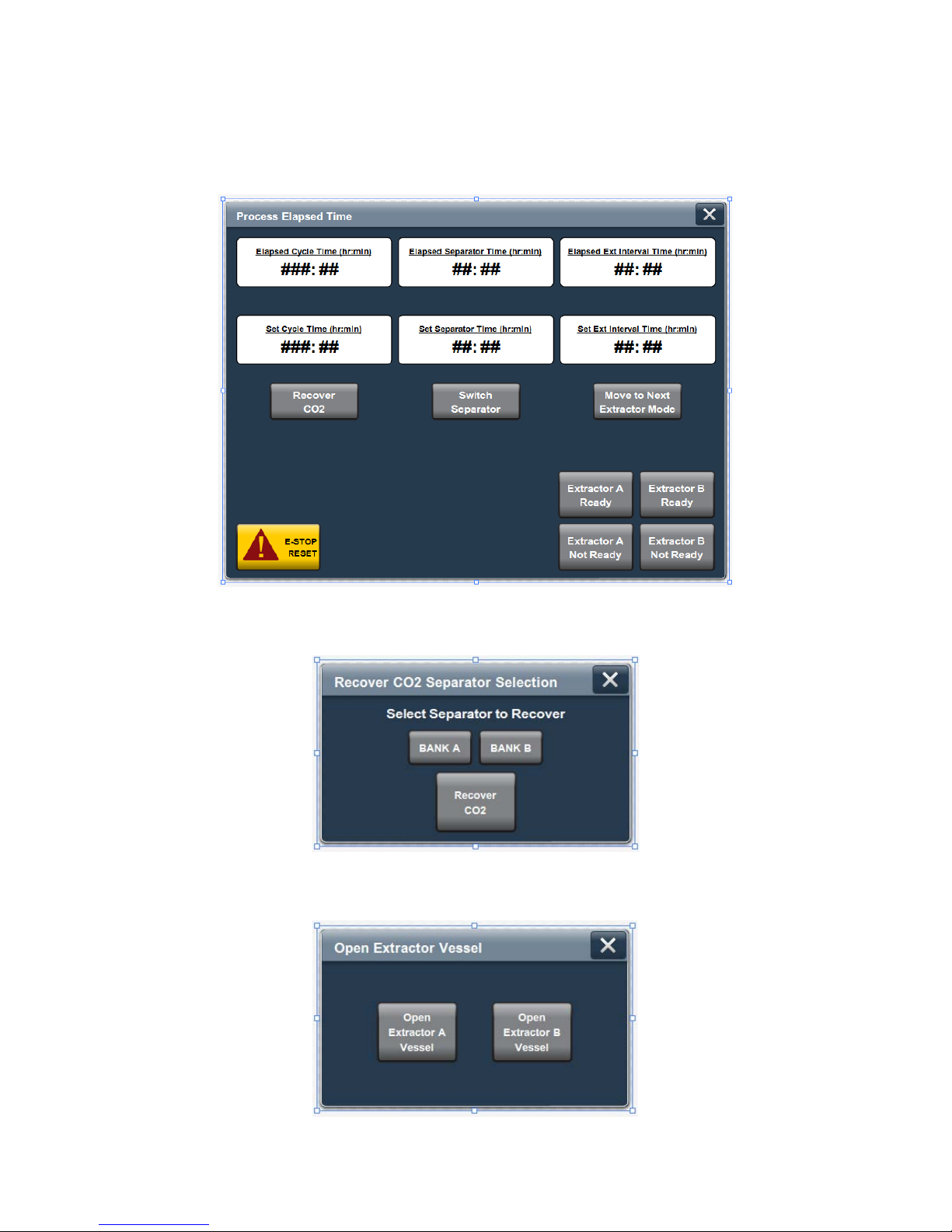
2.2.11.3. Elapsed Time Setting – This Screen can be called up from the bottom middle of the
main screen and allows the operator to change/monitor time settings. In continuous batch
mode the operator will need to go to this screen to verify that extractors are ready to
come online.
2.2.11.4. Recover CO2Separator Selection – This window will popup if the system is recovered
by the user before the end of the cycle.
2.2.11.5. Open Extractor Vessel – This window will popup if the operator selects open extractor
on the manual screen.
Other manuals for 2000PSI THE DUPLEX
1
Table of contents
Other Apeks Laboratory Equipment manuals

Popular Laboratory Equipment manuals by other brands


IKA
IKA SMRA + MRA user guide

Radiometer Analytical
Radiometer Analytical TitraLab TIM960 user guide

MELAG
MELAG Vacuklav 23-B user manual

Thermo Scientific
Thermo Scientific MaxQ 4000 Operating manual and parts list

Daihan Scientific
Daihan Scientific 600.P user manual

Rigaku
Rigaku SmartLab instruction manual

Thermo Scientific
Thermo Scientific Finnpipette Instructions for use

Salvislab
Salvislab Thermocenter TC40 user manual

Dürr Technik
Dürr Technik SICOLAB med Installation and operating instructions

Metrohm
Metrohm ProfIC Vario 6 Anion manual

Heidolph
Heidolph Hei-MIX Titramax 100 operating instructions

Selecta
Selecta BLOOD-BANK A instruction manual