Apeks i.2000 User manual

Updated 4/25/2018 © Apeks LLC, 2014
i.2000 AND 2000PSI
BOTANICAL OIL EXTRACTION SYSTEM
OPERATION MANUAL
WARNING
FAILURE TO FOLLOW THE SETUP AND OPERATION PROCEDURE
PROVIDED IN WITHIN THIS MANUAL MAY VOID THE EXTRACTION
SYSTEM’S WARRANTY
Apeks LLC
150 Commerce Blvd.
Johnstown OH 43031
844-446-4262
www.apekssupercritical.com
Scan this QR code to get the most
recent version of the operating
instructions.

Updated 4/25/20182 © Apeks LLC, 2014
Table of Contents
Page
1. Critical Safety Overview ………………………………………………………………………………………………3
2. System Operation ……………………………………………………………………………………………………..4
2.1. 2000 System Overview …………………………………………………………………………………..…….4
2.2. Automation Overview …………………………………………………………………………………………..4
2.3. Pre-Cleaning …………………………………………………………………………………………………....6
2.4. Depressurizing System After Recovery ………………………………………………………………………6
2.5. Remaining Oil from Separator #1 ……………………………………………………………………………..6
2.6. Closing Separation Vessels …………………………………………………………………………………...8
2.7. Maintenance After Every Run …………………………………………………………………………………9
2.8. Opening Extraction Vessel …………………………………………………………………………………...11
2.9. Removing Spent Material from Extraction Vessel ………………………………………………………….12
2.10. Loading Botanical Material or Other Media …………………………………………………………………12
2.11. Closing Extraction Vessel …………………………………………………………………………………….13
2.12. Chiller Startup …………………………………………………………………………………………………13
2.13. Evacuating System (Pulling Vacuum) ………………………………………………………………………14
2.14. Conducting an Extraction …………………………………………………………………………………….14
2.15. Recommended Operating Parameters ……………………………………………………………………..15
3. Troubleshooting ………………………………………………………………………………………….................17
3.1. Ice on Separator or Collection Cup ………………………………………………………………………….17
3.2. Low Extractor Pressure ………………………………………………………………………………………17
3.3. Extractor Overpressure ………………………………………………………………………………………17
3.4. Low Separator Pressure ……………………………………………………………………………………...18
3.5. Wrong Orifice Size …………………………………………………………………………………………….18
3.6. Differing Separator Pressure ………………………………………………………………………………...18
3.7. Oil Carryover to Separator #2 or Filter Housing …………………………………………………………….18
4. System Maintenance ………………………………………………………………………………………………...19
4.1. Extraction System Maintenance………………………………………………………………….................19
4.2. Diaphragm Compressor Maintenance……………………………………………………………………....20
4.3. Chiller Maintenance …………………………………………………………………………………………..20
5. References ……………………………………………………………………………………………………………21
6. Appendix A. Screen Shot ……………………………………………………………………………………………22
7. Appendix B. Belt Tension Testing/Adjustment …………………………………………………………………….27
8. Diaphragm Pump Priming Instruction ………………………………………………………………………………31
9. Electrical Screw Torque Requirements …………………………………………………………………………….33
10. Piping and Instrumentation Diagram ……………………………………………………………………………….35
11. CO2Phase Diagram …………………………………………………………………………………………………38
12. Pre-Training Checklist ……………………………………………………………………………………………….40
Updated 4/25/20183 © Apeks LLC, 2014
1. Critical Safety Overview
Throughout these instructions, this symbol is used to indicate that the instructions are critically
important to your safety and the safety of your system. Failure to follow the instructions as written
can result in a rapid release of high pressure CO2potentially causing equipment or personnel
damage.
WARNING
Subcritical and Supercritical CO2systems operate under high pressure. Operators must be fully trained and
familiar with the system. Failure to operate the system can result in equipment damage and/or bodily injury.
WARNING
Subcritical and Supercritical CO2systems use large amounts of CO2during operation. Ensure that system is
installed in a well-ventilated area to prevent buildup of CO2 which can cause asphyxiation. Use of a CO2monitor
is strongly recommended.
WARNING
Opening a vessel under pressure can result in a rapid release of pressure and ejection of the material inside the
vessel. DO NOT ATTEMPT TO OPEN A VESSEL UNDER PRESSURE! Always make sure a vent path for the
vessel is opened and the corresponding pressure gage reads zero prior to loosening the vessel hammer unions.
WARNING
Subcritical and Supercritical CO2systems are designed to operate indoors. Extreme temperatures (below 60°F
and above 80°F) will negatively impact the functionality of the system. The environmental temperature range is
for the system, chiller, pump and CO2bottles.
WARNING
Only use Propylene Glycol and distilled water in the chiller and cooling system. Never use Deionized Water in
the chiller or cooling system.
Updated 4/25/20184 © Apeks LLC, 2014
2. System Operation
The following operating instructions are for the Apeks 2000 psi CO2-basedBotanical Oil Extraction systems.
Instructions manuals for the Thermo-Fisher chiller and Diaphragm Compressor are supplied separately.
Failure to follow the instructions provided below may void the warranty of the extraction system and its
components.
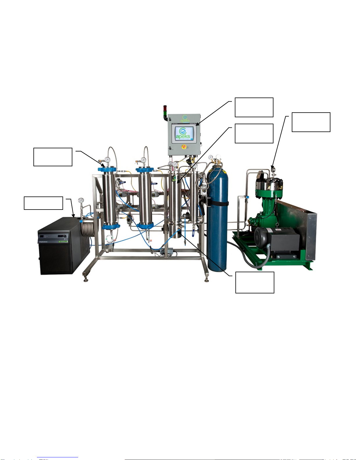
2.1. 2000 System Overview
Figure 1. System Components
NOTE: Alternate system setup shown for clarity, setup type can be requested at time of order,
additional cost may apply
2.2. Automation Overview
2.2.1. The Human Machine Interface (HMI) is a 10-inch color touch screen. Almost all of the inputs,
outputs and human/machine interactions are managed through the HMI. The features are not
controlled or reported through the Diaphragm Compressor or the Chiller.
2.2.2. The HMI has two functions; 1) to provide information and 2) to accept inputs from the operator.
Description of some of the interaction is here:
2.2.2.1. If a display value or message is colored orange, an operator must take action before
progressing forward.
Chiller
Separation
Vessels
Collection
Cup
Extraction
Vessels
Diaphragm
Pump
Controller/
HMI

Updated 4/25/20185 © Apeks LLC, 2014
2.2.2.1.1. Orange indicates that an operator activity is required before the Start button can be
depressed. Messages highlighted orange are indicative of a scheduled maintenance
interval being reached.
2.2.2.2. Red messages indicate that a component of the system has either failed to reach the
minimum operating pressures or temperatures, or that it exceeded the programmed
operating limits. Red messages are typically reserved for alarms that could potentially shut
down the machine if the condition causing the alarm is not returned to normal.
2.2.2.2.1. Red messages may require user acknowledgement or may simply disappear when
an abnormal condition returns to normal parameters. If there is a button that
appears, user intervention will be required.
2.2.2.3. Yellow messages will typically be displayed on a button that has to be pressed to
acknowledge that the operator has read the message before it will disappear.
2.2.3. Any variable or message that needs to be (or can be) controlled by the operator are
graphically raised to illustrate that the “message” is a button. An example of the different
graphical representations is shown below.
Figure 2. Indicator vs. Button
2.2.4. The controller has safety interlocks programmed into it. These safety interlocks prevent unsafe
operations from occurring by monitoring the system parameters and by removing unsafe
action/input control buttons from the HMI. When buttons appear to be missing from the home
screen, it is because the system is performing an operation that would be unsafe in
combination with the missing button/action.
2.2.5. The HMI will provide message popups (in yellow boxes) to instruct the operator what steps are
required next in order in to complete any action selected. Most message popups are also
acknowledgement buttons that must be pressed before any further action can be taken.
2.2.6. The primary operating valves on the Apeks system are air actuated valves controlled by the
systems controller. In the event of an air compressor failure or a power failure all air actuated
valves will return to their normal resting state. Valves 0 and 17B will be normally open and all
others will be closed.
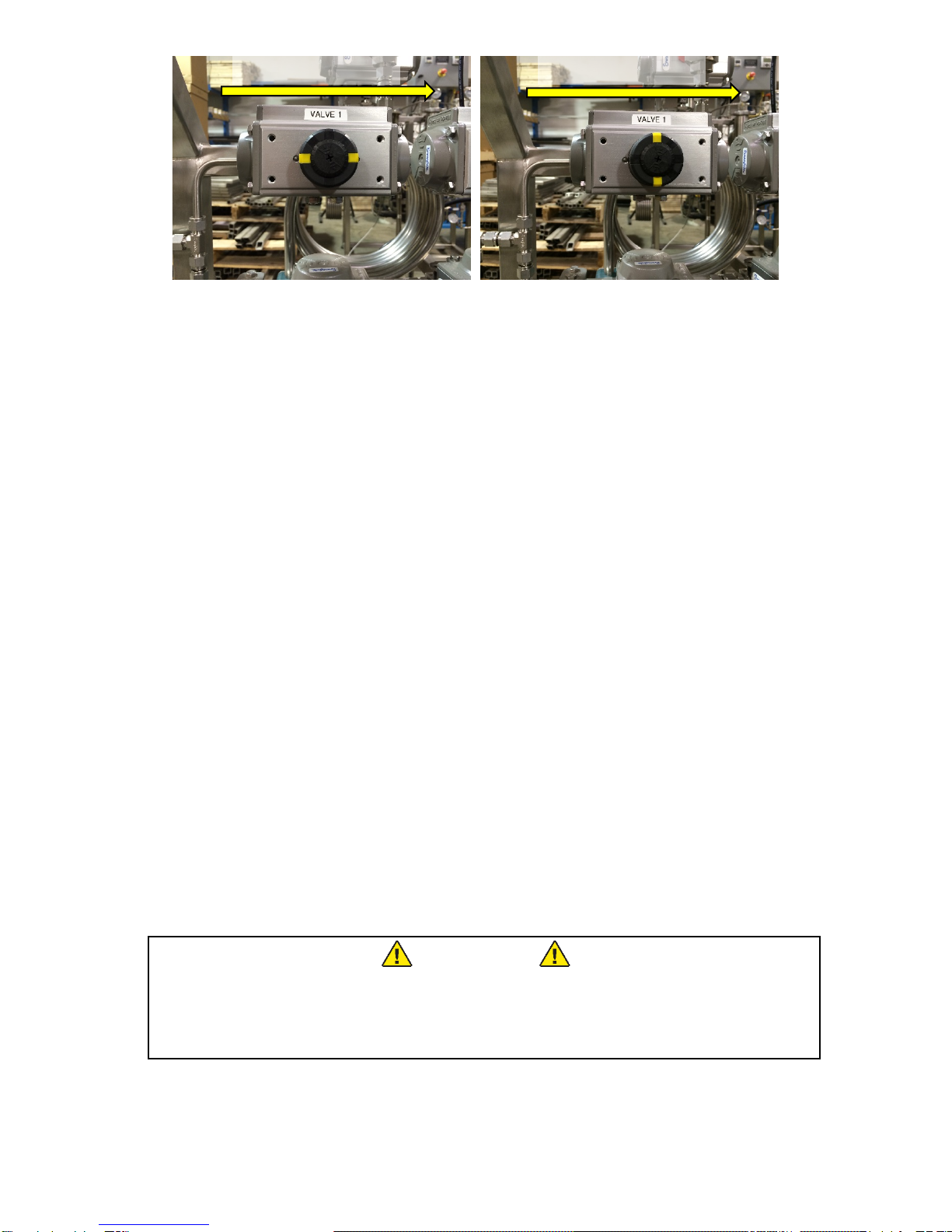
2.2.7. Each air actuated valve has an indicator on the top to inform the operator which valves are
open and which ones are closed. The indicator lines correspond with the flow direction. The
following figure illustrates both and open and closed valve. Note that it does not matter which
way the air actuator is oriented, rather the direction of CO2flow is important.
Title/Output Display
with solid edge
Input Button with
Chamfered edge
Updated 4/25/20186 © Apeks LLC, 2014
Figure 3. a) Valve 1 in the open position, b) Valve 1 in the closed position
2.3. Pre-Cleaning
2.3.1. The Apeks system is constructed from 304 and 316 stainless steel and can be cleaned with
any cleaner that is compatible with both stainless steel and your extracted product. Alcohol
(200 proof) works well for most applications.
2.3.2. The system should be cleaned to the appropriate level (determined by your application and
corresponding regulations) prior to processing each batch of botanical material.
2.3.2.1. Apeks takes great care to clean all systems prior to shipping, however, it is the user’s
responsibility to ensure that the system meets their required level of cleanliness before
processing material.
2.4. Depressurizing System after Recovery
2.4.1. After completion of recovery, Valve 4 (4A and 4B for dual vessel) will open to relieve residual
extractor pressure. A yellow acknowledge button will appear in the home screen
2.4.2. Follow directions in order:
2.4.2.1. Close (turn clockwise) CO2 Bottle(s)
2.4.2.2. Open Valve 10 to relieve separator pressure
2.4.2.3. Press acknowledge box, this will relieve the pressure in the CO2 bottle lines and the rest of
the system.
2.4.3. Open all manual valves.
2.4.4. Turn off the chiller/heater.
2.4.5. NOTE: any time the diaphragm pump stops the system will automatically vent CO2 from valve
0 in order to relieve stress on the diaphragm head.
2.4.6. If system was stopped unexpectedly and system needs recovered proceed to the “Manual
Screen” to recover CO2and then follow steps 1 thru 5.
2.5. Removing Oil from Separator #1
WARNING
DO NOT ATTEMPT TO OPEN A VESSEL UNDER PRESSURE! Always make
sure a vent path for the vessel is opened and the corresponding pressure
gauge(s) reads zero prior to loosening the vessel closure bolts.
2.5.1. Ensure Valve 10 is open
2.5.2. Ensure that the all three gauges on separator vessels (shown below) and separator pressure
on the home screen reads zero.
CO
2
Flow Direction
CO2Flow Direction
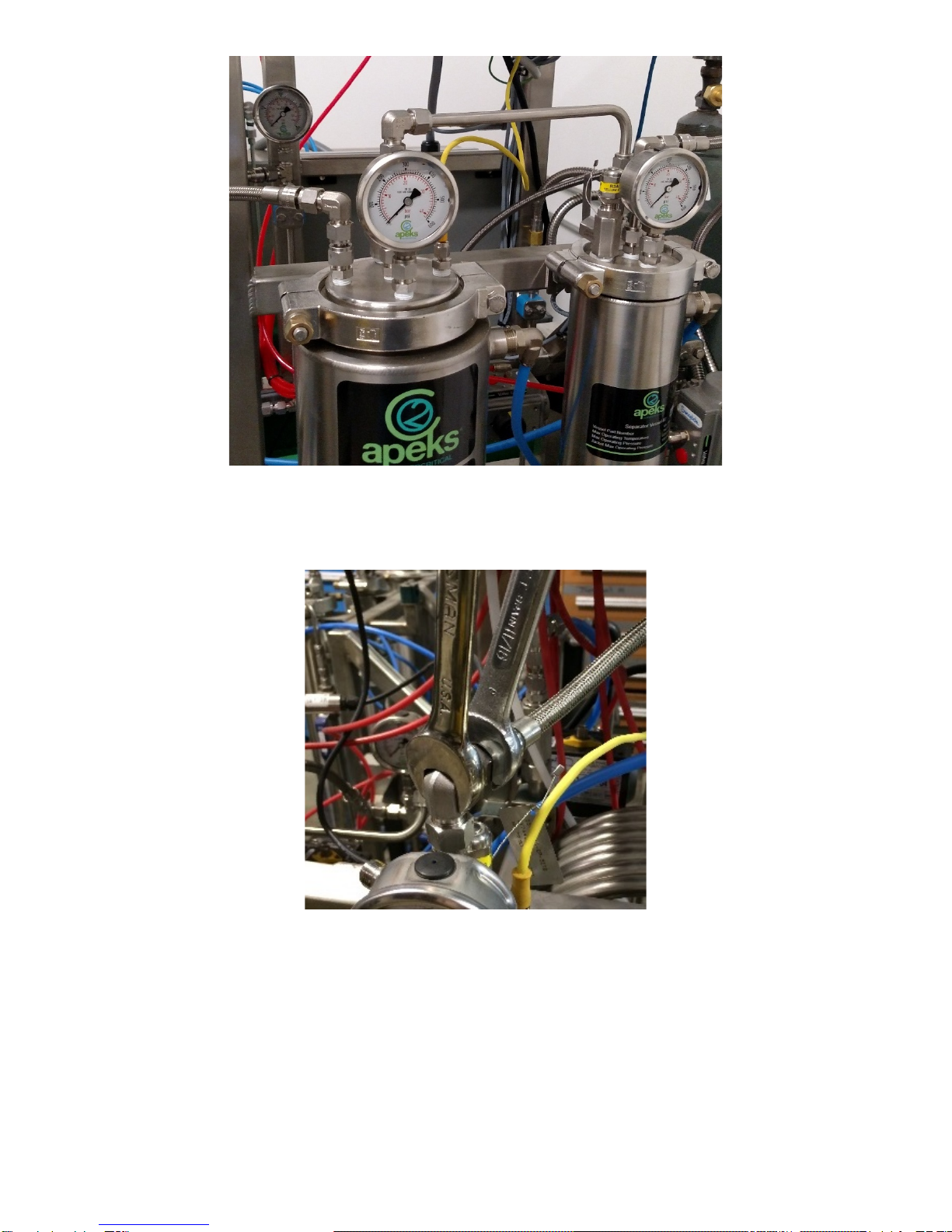
Updated 4/25/20187 © Apeks LLC, 2014
Figure 4. Gauges to Check when Removing Sanitary Clamps
2.5.3. Remove the flexible metal line and connection pipe from the top of the separators. Use two
wrenches to prevent the bending tubes or NPT fittings from loosening in the separator cap.
Figure 5. Illustration of using two wrenches to remove lines
2.5.4. Remove the yellow wire connected to the Separator #1 thermocouple.
2.5.5. Remove the white vent tube attached to the pressure relief.
2.5.6. Use the 5/8-in ratchet wrench to remove the high pressure sanitary clamps from the top of
Separator #1.
2.5.7. Remove the cap from the top of separator.
2.5.8. Collect any available oil from the separator cap.
2.5.9. Use alcohol to clean the caps and orifice tube.
1
3
2

Updated 4/25/20188 © Apeks LLC, 2014
2.5.10. Use the supplied round squeegee or hard plastic scrapper to push any residual oil from the
sides of the Separator #1 down to the bottom and in the collector cup.
2.5.11. Disconnect the two blue water line quick connects on the collection cup.
2.5.12. Attach the collector cup quick connects together and attach the bottom separator 1 quick
connect to the heat exchanger quick connect. This will ensure water flow even if collector cup
connections are not re-attached in assembly.
2.5.12.1.Caution if removing the cup in the middle of a run with the pump on this step must be
followed or the system may automatically shut down due to lack of water flow.
2.5.13. Use caution to support and not to drop the collector cup, remove the high pressure sanitary
clamps from the bottom of the separator 1 with 5/8-in ratchet wrench.
2.5.14. Remove the collection cup from Separator #1.
2.5.15. Collect the oil from inside the collection cup.
2.5.15.1.Note: Oil will be carbonated with CO2 and some dry ice may be present. This carbonation
or dry ice will sublimate without any additional heat. It is sometimes more efficient to
remove the dry ice/oil mixture and place it in collection device (like a Pyrex dish).
Figure 6. Image of collection cup after removal from separator.
2.5.16. Use the round squeegee and alcohol to thoroughly clean the inside of the separator and
collection cup.
2.5.17. Separator #1 and the collection cup must be cleaned after each extraction.
2.5.18. Reassemble separator #1 by reversing the steps above, excluding the connection piping from
Separator #1 to #2.
2.5.19. When reassembling, check gaskets for integrity and groove seals for cleanliness.
2.5.20. Prior to reassembling separator #1 cap, check orifice for clog and orientation.
2.5.21. Reconnect the collector cup water lines with quick connect to original configuration before
turning on the chiller/heater.
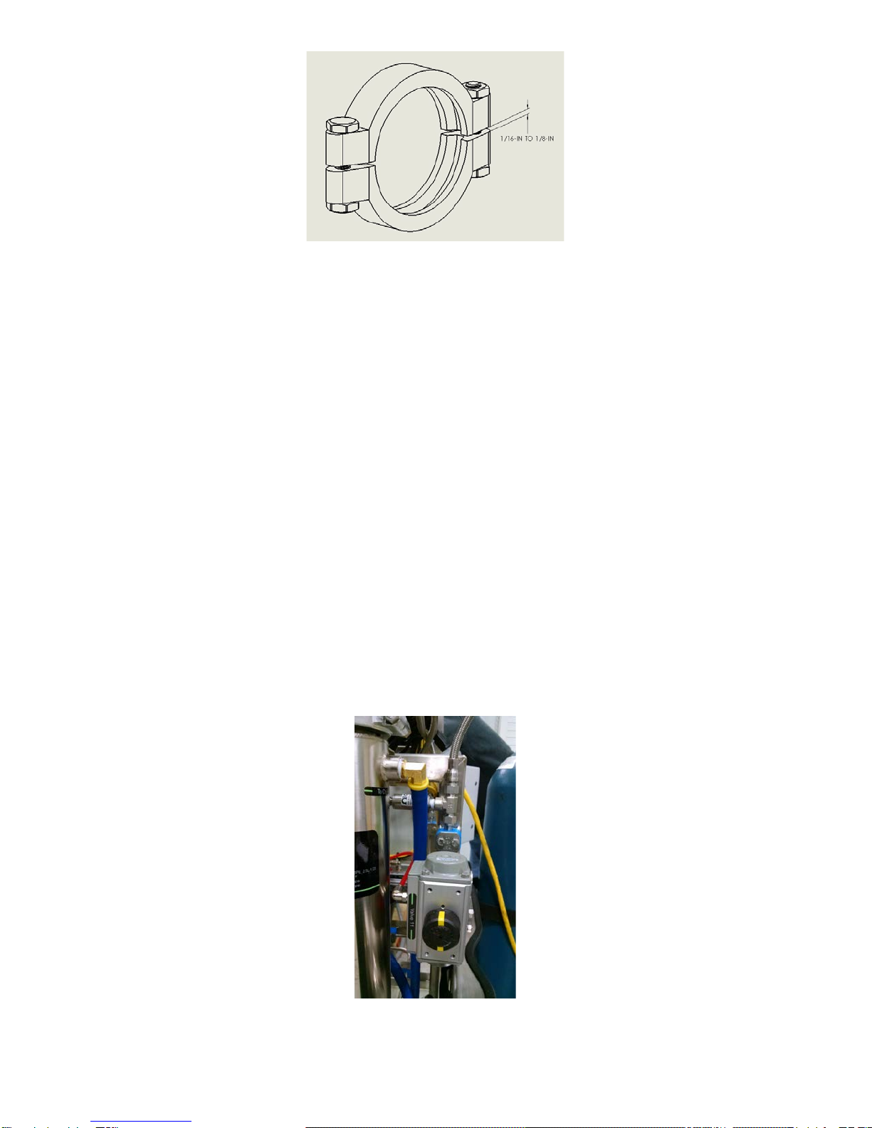
2.6. Closing Separation Vessels
2.6.1. The separators are closed with sanitary clamps.
2.6.2. Clamps are considered tight when both nuts are torqued to 20 ft-lbs. Uses the supplied torque
wrench to accomplish this tightness.
2.6.3. A final visual check before starting the system is good practice, gaps between clamps should
be around a 1/16-In to 1/8-In between opposing sides of the clamp as seen in the figure
below).
Updated 4/25/20189 © Apeks LLC, 2014
Figure 7. Appearance of tight sanitary clamp
2.7. Maintenance After Every Run
2.7.1. Includes harvesting oil and cleaning separator #1 as described above in Section 2.5.
2.7.2. Separator #2
2.7.2.1. Remove Separator #2 inlet and outlets line from separator cap.
2.7.2.2. Remove the top sanitary clamps and inspect Separator #2 for oil carryover.
2.7.2.3. Clean Separator #2 if any oil is present.
2.7.2.3.1. Remove bottom sanitary clamp.
2.7.2.3.2. Use the 3” squeegee and cleaning agent to thoroughly clean the inside of the
separator
2.7.2.3.3. Clean bottom cap and check gasket for integrity and grove cleanliness prior to
reassembly.
2.7.2.4. If there is no oil carryover than check top cap gasket for integrity and groove for
cleanliness prior to reassembling clamps.
2.7.2.5. Clean connection piping between Separator #1 and #2 and reassemble.
2.7.2.6. Ensure separator caps are secured on top and bottom of separators, and all flexible metal
hoses are connected with the exception of the Separator #2 outlet line.
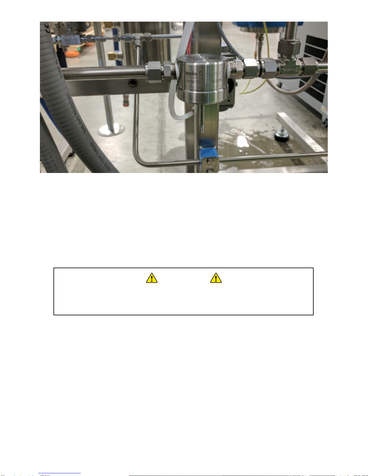
2.7.3. Separator #2 Outlet to Pump Inlet
2.7.3.1. Ensure Valve 11 is open
2.7.3.1.1. If Valve 11 isn’t open, then go to the manual screen and hit “Evacuate”. This will
open up Valve 11.
Figure 8. Valve 11 open.

Updated 4/25/201810 © Apeks LLC, 2014
2.7.3.1.2. If the evacuation button is not present this means there is entrained pressure
somewhere in the system still and you may need to reassemble the vessels and
finish the recovery. Check for pressure on the I/O Screen
2.7.3.2. Disconnect the separator outlet line, if not already disconnected, from the cap of Separator
#2 as shown below.
Figure 9. Image of separator outlet line after being disconnected.
2.7.3.3. Remove the filter housing and filter on the back of the system. Inspect filter and housing for
oil. Clean housing and clean/replace filter as necessary.
Figure 10. Filter Housing.
Disconnect
Here
Updated 4/25/201811 © Apeks LLC, 2014
Figure 11. Filter Housing with bottom and filter removed.
2.7.3.4. Pour cleaning agent into the separator outlet line using the supplied squeeze bottle until
the solvent is colorless coming out the end that was connected to the pump inlet. After no
color appears in solvent, use compressed air to blow out the line to ensuring that NO
residual alcohol remains in the line between the separator and the pump
2.7.3.5. Reconnect the separator outlet lines and reassemble filter.
2.7.3.6. The separator outlet line must be cleaned after every extraction.
2.8. Opening Extraction Vessel
WARNING
DO NOT ATTEMPT TO OPEN A VESSEL UNDER PRESSURE!
Always make sure a vent path for the vessel is opened and the
corresponding pressure gauge(s) reads zero prior to loosening the vessel closure bolts.
2.8.1. This operation cannot be performed during an extraction. The extraction must be stopped
prior to opening the Extraction vessel.
2.8.2. Venting of the Extraction vessel happens automatically at the end of recovery.
2.8.3. If the system is stopped and still has pressure you can go the “Manual Screen”
2.8.3.1. You can choose to either hit “Recover CO2”, which will recover the CO2back into the
bottle.
2.8.3.2. Or “Open Extractor Vessel” button, which will vent all CO2present in the vessel out of
Valve 4.
2.8.3.3. If the extractor is under pressure, the system will require the operator to acknowledge that
they want to vent all the CO2 in the extractor.
2.8.4. When the extractor vessel gauge on top of the vessel and on the home screen both read zero,
it is safe to move to the next step.
2.8.5. Use the supplied rubber mallet to loosen the extractor hammer unions from the top or bottom
flange.
Updated 4/25/201812 © Apeks LLC, 2014
2.8.5.1. CAUTION: Extractor flange can weigh up to 50lbs and care should be given to avoid
damage and injury.
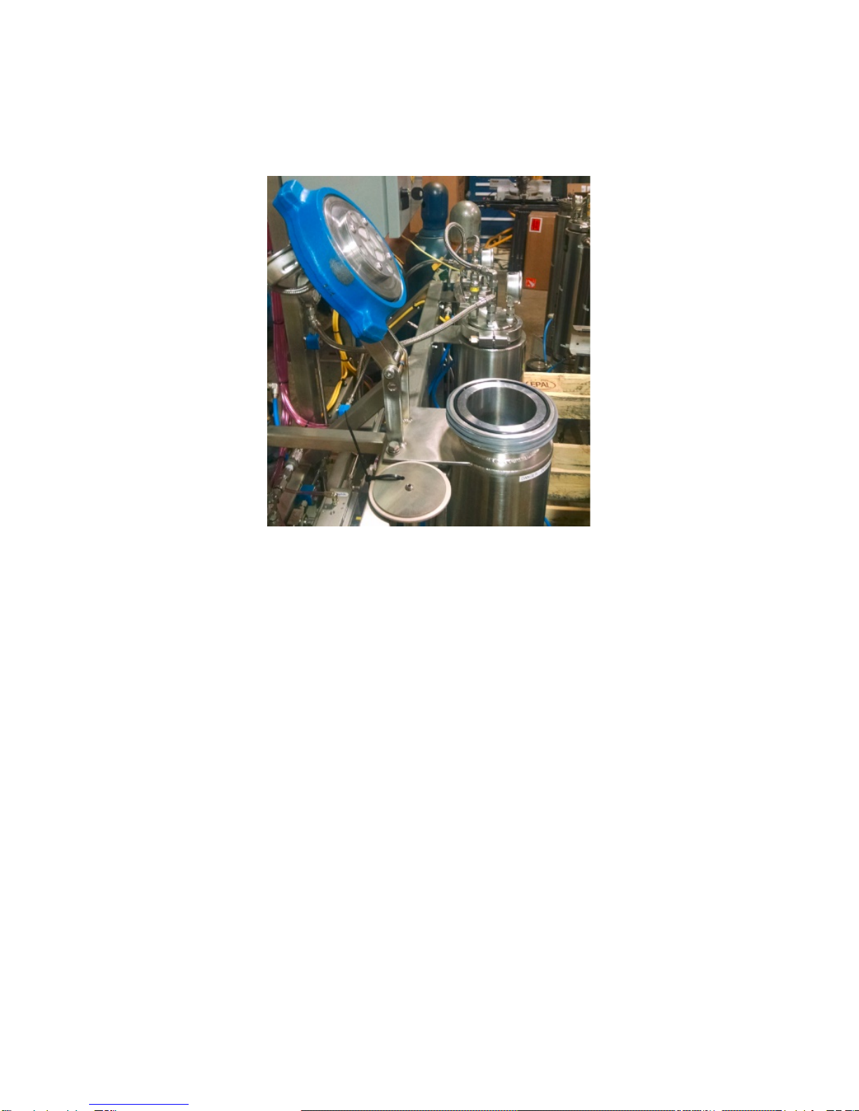
2.8.6. Pivot the top flange toward the back and let it rest on the integral hinge stops. The bottom
hammer union may not have a hinge, and must be lowered gently to prevent injury or damage
to the remote probe and/or hammer union.
2.8.6.1. Use caution not to scratch or otherwise damage the sealing surfaces on the flanges.
Figure 12. Appearance of extractor vessel in open condition.
2.9. Removing Spent Material from Extraction Vessel
2.9.1. Once the extraction vessel is open, the spent botanical material can be removed. It is
recommended to remove all material from the top of the extractor using a large shop vac.
2.9.2. Alternatively, the bottom vessel closure can be opened using the same instructions provided
above. With the bottom closure open the botanical will fall out of the vessel and can be
collected in a bag or other collection device.
2.9.2.1. WARNING: you will have to remove the temperature probe before opening the bottom
vessel closure. Failure to do so may result in bending and/or damaging the temperature
probe
2.9.2.2. CAUTION: removing material from the bottom can cause material to get into threads on
the closure nut. Threads will need to be cleaned before reassembly.
2.9.2.3. CAUTION: Extractor flange can weigh up to 50lbs and care should be given to avoid
damage and injury.
2.10.Loading Botanical Material or Other Media
2.10.1. Prior to loading material visually check temperature probe and filter at the bottom as best you
can from the top of extractor vessel.
2.10.1.1.CAUTION: Extractor flange can weigh up to 50lbs and care should be given to avoid
damage and injury.

Updated 4/25/201813 © Apeks LLC, 2014
2.10.2. Material to be extracted is loaded directly into the extraction vessel. A supplied funnel can be
used to help minimize spillage.
2.10.2.1.Typically, botanicals perform best in CO2 extractions when ground to a particle size
between 200 µin and roughly the consistency of coffee grounds.
2.10.2.2.Any amount of material can be loaded into the Extraction Vessel – the vessel does not
have to be full in order to operate correctly.
2.10.3. Gentle compression or packing can be used to increase the amount of material loaded in the
vessel, however heavy compaction should be avoided because it can cause channeling of
CO2 during the extraction process.
2.11.Closing Extraction Vessel
2.11.1. Ensure all sealing surfaces are clean and free of debris.
2.11.2. Check the Cup seal or O-ring for any visible damage or defects. Replace if necessary.
2.11.3. Ensure the thread of the extractor are free of debris and greased with the supplied bottle of
anti-seize as shown below.
Figure 13. Supplied bottle of Anti-Seize and threads
2.11.4. Thread on the hammer union. Use supplied rubber mallet to fully close vessel 3 to 5 hits past
hand tight. The nut should close to approximately the same location each time. If it does not
then there may be debris in the threads that needs cleaned out.
2.11.4.1.If threads need cleaning remove all anti-seize lubricant from threads on both the vessel
and the nut.
2.11.4.2.Once all old material is removed reapply thin new layer.
2.12.Chiller Startup
2.12.1. Every 80 hours verify chiller coolant level in chiller reservoir. If necessary, top off appropriate
mix of distilled water and propylene glycol. Glycol percentage can be determined using a
refractometer with is available on the online store.
2.12.2. Every 40 hours clean air filter on front of chiller.
2.12.3. Verify chiller cooling lines are connected to the extraction system
2.12.4. Basic chiller commands
2.12.4.1.Turn on chiller: press the power button on the front of the chiller. If that does not work
check to make sure the chiller is connected to power and the breaker on the back of the
chiller is on.

Updated 4/25/201814 © Apeks LLC, 2014
2.12.4.2.Set the target pressure: from the main screen, when setpoint is highlighted press enter to
take you to the current setpoint. To adjust setpoint press enter again till setpoint is flashing.
Use arrows to turn the setpoint up or down and then save by pressing enter
2.12.4.3.Other options: other options such as changing units and monitoring values are located
under the menu section. Refer to chiller manual for more detail.
2.12.5. Check I/O Screen to verify there is water flow. If no water flow is detected check connections.
2.13.Evacuating System (Pulling Vacuum)
2.13.1. After loading material, and ensuring all vessels are closed and ready for normal operation,
from the Home Screen (see Figure A1), click the Manual Screen Button.
2.13.2. From the Manual Screen (see Figure A2), click the Evacuate Button.
2.13.2.1.Evacuation button will not appear if there is any pressure in the system. Refer to the I/O
Screen to find where there is pressure and relieve
2.13.3. Verify that all the gauges on the system display zero pressure.
2.13.4. Verify that the supplied vacuum pump is filled with the appropriate oil.
2.13.4.1.Refer to the vacuum pump owner’s manual for more detailed information
2.13.5. Connect the vacuum gauge, blue vacuum hose and vacuum pump to the Evacuation valve on
the bottom of Separator #2.
2.13.6. Open the Evacuation Valve.
2.13.7. Turn on the vacuum pump.
2.13.8. Allow the pump to run for approximately 5-min or until the gauge is below 25 inHg (inches
mercury).
2.13.8.1.If the vacuum gauge does not reach -20 inHg, there may be a leak in the system or a
vessel not closed
2.13.9. Close the Evacuation Valve.
2.13.10. Turn off the vacuum pump
2.13.11. Disconnect the pump assembly (vacuum gauge, blue vacuum hose and pump).
2.13.12. Press the message button acknowledging that the evacuation is complete.
2.13.13. Return to the Home Screen
2.13.14. CAUTION: Never depressurize separation vessels with the evacuation valve while vacuum
pump or gauge is attached.
2.14.Conducting an Extraction
2.14.1. If the green start button is not present at the bottom of the home screen, then do one of two
things:
2.14.1.1.Push the orange button on the bottom of the home screen that says maintenance is
required, and this will then turn into a green start button.
2.14.1.2.Push the green button on the top right corner of the screen that says “Return to Auto
Mode”, and then a green start button will appear on the bottom of the home screen.
2.14.2. Verify that a 50-lb, 75-lb or 100-lb cylinder of CO2with a sufficient amount of CO2is connected
to the system. Refer to the Pre-Training Checklist for suggested bottle quantities. Any time the
bottle has less than 400psi, the pressure is considered low.
2.14.3. Verify that material is loaded into extraction vessel and extraction vessel is properly closed.
2.14.3.1.The system can be run with no material in the extraction vessel. This can be used as a
way to clean the stainless-steel tubing upstream of the separation vessel.
2.14.4. Verify that the Separator vessels are both closed and sanitary clamps are tight (torqued to 20
ft-lbs).
2.14.5. Press the Start button on the home screen.

Updated 4/25/201815 © Apeks LLC, 2014
2.14.6. After pressing start, the system will prompt the operator to follow the following steps.
CAUTION: Failure to follow prompts could result in serious injury.
2.14.6.1.Set Extractor Pressure (between 900-psi and 1900-psi)
2.14.6.2.Set the System Run Time (between 1-hour and 48-hours)
2.14.6.2.1.The recommended run time is dependent on the material being extracted and the
extraction parameters but is typically between 1.5 to 3 hours per pound. Refer to the
Recommended Parameters section
2.14.6.3.Verify chiller is connected, turned on and set to the correct temperature.
2.14.6.4.Verify the Extractor is properly closed.
2.14.6.5.Verify the Separator is properly closed.
2.14.6.6.Close Valve 10 and Evacuation Valve (if evacuation was not conducted these may be
open, if it was then they should already be closed).
2.14.6.7.Open the CO2 Bottles.
2.14.6.8.If you have a single extraction vessel the system will start filling the vessels with CO2 to
the target extractor pressure.
2.14.6.8.1.If you have two extraction vessels the screen will prompt you to choose which
extraction vessel you will be using, either “a” (Extractor A only), “b” (Extractor B only)
or “c” (both extractor A and B at the same time.
2.14.6.8.2.After choosing which extraction vessel(s) you will be using, the screen will prompt
you to close and/or open valves 3A and 7A or 3B and 7B depending on which
extraction vessel(s) you chose to run.
2.14.6.8.3.Then the system will start filling the vessels with CO2 to the target extractor(s)
pressure.
2.14.6.9.During the filling stage the Home Screen will display a blue box labeled “Startup” to inform
the operator of the systems current activities.
2.14.7. Once the target extractor pressure is reached, the system information box will change from
“Startup” to “Running”. An additional information box will appear indicating the direction of the
flow, either “Forward Flow” or “Reverse Flow”.
2.14.7.1.Forward flow refers to CO2 entering the top of the vessel and exiting the bottom. Reverse
flow enters the bottom and leave the top.
2.14.7.2.The system switches the flow direction every run to flow clean CO2 through the filter
elements on the extraction vessel.
2.14.8. The system will continue in run mode until it reaches the target run time, at which point it will
begin recovering the CO2into the CO2cylinder. The information box will switch from
“Running” to “Recovering”.
2.14.9. At the end of recovery, the system will automatically vent the extraction vessel but the
separation vessels will have approximately 100-psi in them. The system will provide message
boxes to instruct the operator through the final shut down process. The prompts are:
2.14.9.1.Close the CO2Cylinders.
2.14.9.2.Open Valve 10.
2.14.10. Once the operator acknowledges that the CO2cylinder are closed and Valve 10 is open, the
system will open all valves, vent any trapped CO2and wait for the next command
2.15.Recommended Operating Parameters
2.15.1. Recommended default parameters are intended as a starting point and it is up to the operator
to determine best results for their operation. Please note that ambient temperature effects
parameters and the system will take an hour to equalize out.
2.15.2. Subcritical runs result in lighter color oils and less waxes while supercritical runs decrease
time and can increase yield.

Updated 4/25/201816 © Apeks LLC, 2014
2.15.3. PDC 3 Diaphragm Compressor
Subcritical: Target Pressure: 1,200 psi
Chiller Setting: 70 - 75F
Propylene Glycol Percentage: 10%
Orifice Size: 22
Resultant Separator Pressure: 350-400psi
Resultant Separator Temperatures: +/- 5 degrees around 25F
Extraction Time: 2-3 hours per pound
Supercritical: Target Pressure: 1,800 psi
Chiller setting: 105 - 110F
Propylene Glycol Percentage: 10%
Orifice Size: 18
Resultant Separator Pressure: 350-400psi
Resultant Separator Temperatures: +/- 5 degrees around 35F
Extraction Time: 1-2 hours per pound
2.15.4. PDC 4 Diaphragm Compressor
Subcritical: Target Pressure: 1,200 psi
Chiller Setting: 70 - 75F
Propylene Glycol Percentage: 10%
Orifice Size: 37
Resultant Separator Pressure: 350-400psi
Resultant Separator Temperatures: +/- 5 degrees around 25F
Extraction Time: 2-3 hours per pound
Supercritical: Target Pressure: 1,800 psi
Chiller setting: 105 - 110F
Propylene Glycol Percentage: 10%
Orifice Size: 29
Resultant Separator Pressure: 350-400psi
Resultant Separator Temperatures: +/- 5 degrees around 35F
Extraction Time: 1-2 hours per pound

Updated 4/25/201817 © Apeks LLC, 2014
3. Troubleshooting
3.1. Ice on Separator or Collection Cup
It is normal for the high pressure clamps and flexible metal lines on the top of the separator to form ice
during operation. If ice is forming on the outside of the separator vessels this is an indication that there
could be a flow restriction inside the separator cooling jacket. The system should be shut down by pressing
the Recover CO2Button on the Manual screen. This will put the system into recovery mode so that the
cooling system can be inspected.
Ensure that the chiller/heater is turned on. Ensure that all blue coolant lines are properly connected.
Ensure that the collection cup coolant lines are properly connected to the first separator. Ensure that the
correct size orifice is being used inside Separator 1. Normal operating pressures within the separators is
between 320-400psi. If pressures are much lower than 250psi, then ice may start to form on the
separators. Also ensure that the temperature of the surrounding environment is no colder than 60°F, it is
possible for the chiller/heater to have difficulty maintaining system temperatures if the surrounding
environment is to cold.
Do not attempt to work on the cooling system while the system is running.
3.2. Low Extractor Pressure
If the extractor pressure is unable to meet the target pressure, first verify that the CO2cylinder has
sufficient CO2(bottle gauge above 400 psi). If the bottles have plenty of CO2, check to see if the orifice
size is too large (if separator pressure stays above 400 psi this may be an indication). Finally, check to see
if the pump outlet is hot (Caution: can be up to 160 F). If pump outlet is cool, the pump may have lost
prime, follow priming instructions in Appendix.
3.3. Extractor Overpressure
The valveless expansion technology uses a small orifice to regulate pressure. This orifice can become
plugged when foreign material is entered into the plumbing between the extraction vessel and separator
vessel
In the event that separator pressure decreases and/or extractor pressure increases causing an extractor
high pressure fault, it is most likely a clogged orifice or your orifice you are using is too small. Follow the
steps below to clear an orifice clog:
i. From the Home Screen, Press the Manual Screen Button.
ii. From the Manual Screen, Press the Service Separator Button.
iii. Wait for the system to provide a message popup indicating it is safe to Open Valve 10 and
clean the orifice.
iv. Open Valve 10
v. Verify that both Separator vessel gauges read zero.
vi. Remove the CO2 lines from the top of the separators. Use two wrenches to prevent from
bending tubes or the NPT fittings from loosening in the separator cap.
vii. Remove the yellow wire connected to the Separator #1 thermocouple.
viii. Remove vent tube from relief valve.
ix. Use the 5/8-in ratchet wrench to remove the high pressure sanitary clamps from the top of
Separator #1.
x. Remove the cap from the top of Separator #1.
xi. Ensure you are using the correct size orifice and inspect for clogs.

Updated 4/25/201818 © Apeks LLC, 2014
xii. Clean the orifice by soaking it in alcohol and blowing it out with compressed air. Verify the
orifice is clear by looking through it.
xiii. An orifice cleaning tool is available on the online store for stubborn clogs.
xiv. Reassemble the orifice.
xv. Replace the separator cap and tighten the clamp bolts to 20 ft-lbs.
xvi. Reinstall the CO2 connections and the thermocouple wire.
xvii. Close Valve 10.
xviii. Press the popup message button when orifice is reinstalled, the high pressure clamps are tight
and the flexible hoses are reconnected.
3.4. Low Separator Pressure
Low Separator pressure is typically caused by one of two things (an orifice clog or the wrong size orifice
installed). If the system has been operating has lower than normal separator pressure or does not seem to
equalize this may be an indication of a clogged or partially clogged orifice. To correct an orifice clog refer
to the instructions in the section above (Extractor Overpressure).
3.5. Wrong Orifice Size
Orifice size dictates the relationship between the separator and extractor. The main goal is to maintain the
separator pressure around 320-400 psi. While the system may run at higher or lower pressure just fine,
CO2 flow may not be optimal with lower pressures or you may be at risk for more carryover with higher
pressures. The smaller the orifice size the lower the separator and vise versa. Several orifice sizes are
shipped with each machine that will run any parameter on the machine but additional sizes for any specific
optimization are available on the online store. Follow service separator instructions to change orifices.
3.6. Differing Separator Pressures
Differing Separator Pressures means there is a clog in the tubing between the two separators as they
should be around the same pressure (+/- 10 psi). To check for obstructions, follow the service separator
instructions in Section 3.3 and check tubing.
3.7. Oil Carryover to Separator #2 or Filter Housing
Oil carryover can be detected during every run maintenance when cleaning the Separator #2 outlet to
pump inlet and when spot checking Separator #2. Light carryover can/will occur. The presence and
severity of oil is an indication of carryover to the pump. While slight oil can be tolerated, the pump was not
designed to have oil circulating through it. Oil carryover will reduce the life of the pump and can damage
the pump if severe. If a large amount of carryover is detected (more than a couple grams) check the
following items during the next run:
i. Separator temperatures are above 40F after system is equalized, usually after 1 hour after
initialing. The temperature set point on the chiller has a direct relationship with separator
temperature. Turn the set point on the chiller down until separator temperature is below 40F.
ii. Extreme cold temperatures in separators cause oil carryover as well. If the separator is
encased in a block of ice the temperature is more than likely a tad too cold. Ensure that the
chiller is on and correctly functioning before beginning a run, water lines are correctly
assembled between the collector cup and the separator, and the water line quick connects
have disengaged the check valves.
iii. For both case check water line connections, chiller settings and water to propylene glycol
percentages.

Updated 4/25/201819 © Apeks LLC, 2014
4. System Maintenance
This maintenance schedule is based on the maintenance timer on the Maintenance Screen (see Appendix A).
4.1. Extraction System Maintenance
Included with each system is a small squeeze bottle to help with proper maintenance and cleaning of your
systems C02 lines. Alcohol (200 proof) is a typical and acceptable cleaning agent. Please label the bottle
accordingly.
Figure 14. Front and back of chemical squeeze bottle
Frequency
Maintenance Item
After Each
Extraction
•Remove extracted oil from collector cup and separator walls, clean walls and
cup with alcohol.
•Check separator 2 for oil carryover and clean if necessary.
•Inspect separator gaskets and grooves prior to reassembly.
•Clean piping between separator 1 and 2 with alcohol.
•Clean Separator 2 CO2outlet to pump inlet, ensure valve 11 is open.
•Remove spent material from the extraction vessel by vacuuming it out through
the top flange.
•Verify the extractor filters are clear and free of debris
•Check extraction vessel O-rings and O-rings groove sealing surfaces for
damage – replace if necessary
•Inspect the surfaces on Extraction vessel to make sure they are free from dust
and debris. Failure to clean surfaces properly can cause vessel not to seal
properly or damage to the cup seal.
Every 80
Hours
•Run the system “empty of plant material” for 1 hour to clean the high pressure
side of the system and extraction vessel(s)
Yearly
•Check torque on all screws in electrical panels (see Appendix D)
Resource
Apeks online store
http://www.apekssupercritical.com/online-store/
Updated 4/25/201820 © Apeks LLC, 2014
4.2. Diaphragm Compressor Maintenance
See Diaphragm Compressor Manual for specific instructions on maintenance items. Below is general system
information.
Frequency
Maintenance Item
Daily
•Check oil level
•Check oil pressure
•Listen for abnormal noise or vibration
•Check Leak Detection System status
Every 500
Hours
•Change Diaphragm Compressor Filter located on suction side tubing.
•Check belt tension (See Appendix B)
•Clean process check valves
Every 1500
Hours •
Preform regular oil change
•Check torque on all screws in electrical panels (see Appendix D)
Every 4000
Hours
•Replace diaphragms and o-rings in process head
•Clean and inspect oil inlet check valve
•Clean and inspect oil relief valve
•Inspect crankcase assembly
•Inspect compressor lower head
•Clean and inspect injection pump assembly
4.3. Chiller Maintenance
See Chiller Manual for specific instructions on maintenance items. Below is general system information.
Frequency
Maintenance Item
Weekly
•Check fluid level
•Check fluid filter bag and clean/replace as necessary
•Listen for abnormal noise or vibration
•Check for any leaks
•Clean condenser filter (air filter) on front bottom of chiller
Every Month
•Check/Clean fluid diffuser
Every 6
months
•Replace cooling fluid
This manual suits for next models
1
Table of contents
Other Apeks Laboratory Equipment manuals

Popular Laboratory Equipment manuals by other brands

10x Genomics
10x Genomics Chromium Controller Readiness Test manual

UVITEC Cambridge
UVITEC Cambridge FIREREADER MAX User & service manual

Drinkpod
Drinkpod 1000 Pro Series Use & care guide

Benchmark
Benchmark Orbi-Shaker CO2 Operation manual

Sigma
Sigma SGP-1000-2 instruction manual

VGE
VGE MultiMax Pro Installation & user manual


