IEC MASH BATH User manual
Mash Bath
I N D U S T R I A L E Q U I P M E N T & C O N T R O L P T Y . L T D .
6 1 - 6 5 M c C l u r e S t . T h o r n b u r y . 3 0 7 1 M e l b o u r n e . A u s t r a l i a
T e l : 6 1 ( 0 ) 3 9 4 9 7 2 5 5 5 F a x : 6 1 ( 0 ) 3 9 4 9 7 2 1 6 6
E m a i l : i e c @ i e c p l . c o m . a u
M A S H B - 2 0 1 9 0 3 1 4 . d o c 1 4 - M a r - 1 9
1
THE ‘IEC’ MASH BATH
This manual covers all models for 2019
Designed and Manufactured by : Industrial Equipment & Control Pty. Ltd.
. Melbourne
Australia.
MASHB-2018-02-01.pdf
BENCH MODELS:
6, 9, 12 and 16 head.
Image shows 9 Head,
with ‘touch panel’
control system and
distilled water heating
tubes.
Belts are no longer
used for stirrer drives.
FLOOR MODELS:
16, 20, 25 and 30 head.
Image shows 20 Head,
with ‘touch panel’ control
system and distilled
water storage and
dispensing.
Belts are no longer used
for stirrer drives.
Models 290 & 290/530
: belt free stirrer drive

Mash Bath
I N D U S T R I A L E Q U I P M E N T & C O N T R O L P T Y . L T D .
6 1 - 6 5 M c C l u r e S t . T h o r n b u r y . 3 0 7 1 M e l b o u r n e . A u s t r a l i a
T e l : 6 1 ( 0 ) 3 9 4 9 7 2 5 5 5 F a x : 6 1 ( 0 ) 3 9 4 9 7 2 1 6 6
E m a i l : i e c @ i e c p l . c o m . a u
M A S H B - 2 0 1 9 0 3 1 4 . d o c 1 4 - M a r - 1 9
2
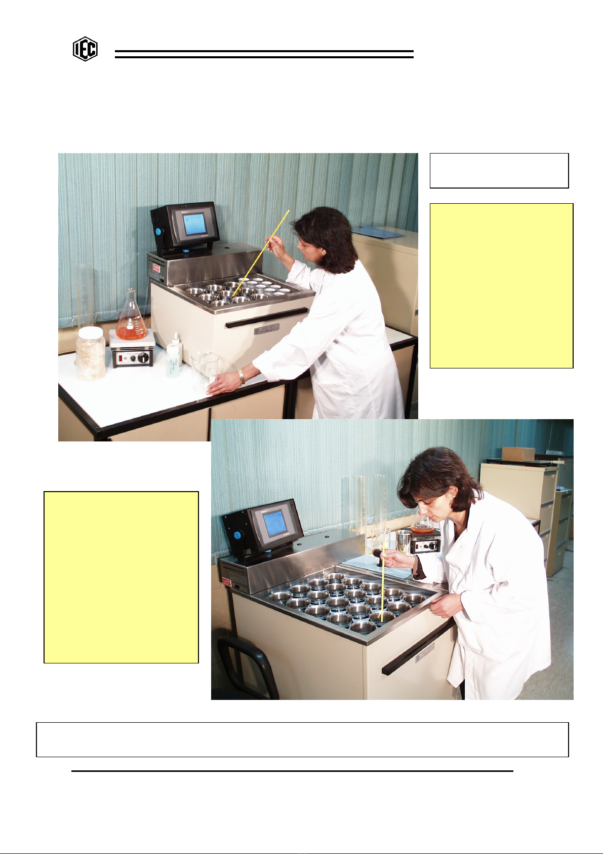
Bench models do not have distilled water storage or dispensing, but the
special bath lids carry tubes to carry distilled water that heat with the
bath and are used to add volume to the sample as required.
Floor standing models have temperature controlled distilled water
storage and a quick action dispensing system.
All models are controlled by a
‘touch panel’ system that
eliminates all buttons and
switches. The program is
visible to the user as a graph
with a ‘time line’ progressing to
indicate the status.
All the required information is
displayed and all programs can
be fully edited to suit the
requirements of the laboratory.
Floor models are
complete with a rugged
dispensing gun which is
used to initially fill the
pots and to add the
distilled water during the
mash, if required.
The gun is fitted with a
press switch which
initiates the discharge of
the correct volume of
distilled water at the
correct temperature as
set in the program.
The gun is neatly parked
in a receptacle in the
removable cover of the
storage tank.

Mash Bath
I N D U S T R I A L E Q U I P M E N T & C O N T R O L P T Y . L T D .
6 1 - 6 5 M c C l u r e S t . T h o r n b u r y . 3 0 7 1 M e l b o u r n e . A u s t r a l i a
T e l : 6 1 ( 0 ) 3 9 4 9 7 2 5 5 5 F a x : 6 1 ( 0 ) 3 9 4 9 7 2 1 6 6
E m a i l : i e c @ i e c p l . c o m . a u
M A S H B - 2 0 1 9 0 3 1 4 . d o c 1 4 - M a r - 1 9
3
GENERAL DESCRIPTION:
A high quality, electronically controlled Mash Bath containing up to 8 selectable programs
that relate bath temperatures with times. The IEC Bath is carefully designed to
automatically perform the standard mash sequences as required by the various brewing,
barley, malt and cereal industries, however its versatility permits it to be easily programmed
for variations to these standard tests.
Some of the features of the ‘IEC’ Mash Bath are:
ALL MODELS:
•Fully adjustable touch screen controller is mounted above the rear cover to provide a
narrow machine with small footprint. Screen can be angled to suit any user. If
desired, the controller can be removed from the machine and mounted remotely.
•Fully sealed ‘wipe clean’ touch screen with no knobs or switches to clean.
•Outer panels are easy to remove and tools not required. All the front and side
panels are powder coated for excellent resistance to corrosion.
•Machine can be supplied for either single or three phase power.
•Stainless Steel construction and the whole design has been developed for easy
access and quick and simple maintenance.
•Very strong but quiet magnetic stirrers stir the mash samples from below the tank
and 30 to 40mm long laboratory ‘spinbars’ can be used in each sample pot.
•Stirrers are driven directly by independent motors. Belts and pulleys are no longer
used. If one drive should fail, it is automatically shut down without disturbing any
other drives. Drives are easily replaced in minutes.
•The temperature / time ramping of the bath is held to close accuracy.
•The bath automatically preheats the water to the programmed temperature and
provides an audible alert to advise when preheat is achieved.
•All audible alerts can be silenced or reinstated by the momentary press of a button
and can be altered in loudness to suit the environment.
•Different programs are easily created and any program can be selected by the touch
panel controller. Even the names of the programs can be edited to suit your lab.
•The special IEC designed bath lid accepts ‘Industry Standard’ 500ml stainless steel
beakers (pots). The lid seals grip gently to the pots to hold them firmly against
floating when empty and to prevent unwanted steam in the laboratory. The lid is
easily removable without tools for cleaning but cannot be dislodged when fitted for
operation.
•The sides of the bath are lagged to conserve energy.
•At the end of the selected program, a selectable cooling option is provided for either
a hot bath finish or to cool the samples slowly or to cool them quickly.
•The samples are stirred by magnetic stirrers below the tank. Automatic ON / OFF /
INTERMITTENT control over the magnetic stirrers is part of each program but
manual override is also provided.
•The ‘IEC’ Mash Baths have our specially designed quiet circulation pumps that run
fully immersed inside the main and the distilled water tanks for best temperature
control and for reduction in the complexity of pipes and hoses.
•Good bath circulation ensures accurate temperature through the whole bath.

Mash Bath
I N D U S T R I A L E Q U I P M E N T & C O N T R O L P T Y . L T D .
6 1 - 6 5 M c C l u r e S t . T h o r n b u r y . 3 0 7 1 M e l b o u r n e . A u s t r a l i a
T e l : 6 1 ( 0 ) 3 9 4 9 7 2 5 5 5 F a x : 6 1 ( 0 ) 3 9 4 9 7 2 1 6 6
E m a i l : i e c @ i e c p l . c o m . a u
M A S H B - 2 0 1 9 0 3 1 4 . d o c 1 4 - M a r - 1 9
4
FLOOR MODELS:
•Floor models are mounted on small wheels for ease of moving for cleaning.
•The cabinet provided below the bath is for storage of Mash Beakers (pots), lab
equipment and spare parts.
•The distilled water is either gravity or pressure filled automatically from the
laboratory’s supply, which is sometimes mounted on the wall. Water level and
circulation in this tank is automatically controlled and the distilled water is
temperature held to within +/- 0.3 degrees. The tank is fitted with a cold water heat
exchanger coil for quick cooling of the distilled water between mashes. This cooling
can be instigated within the program to have the distilled water cold at the end of the
program. This avoids delays between mashing cycles..
•A special hand held gun with press switch dispenses the correct volumes of distilled
water into the pots as required both prior to mashing and at the ‘top-up’ time during
the cycle. An alert sounds at exactly the correct moment to remind the operator to
dispense the water. By using the touch screen in EDIT mode, the d/w volumes are
edited into each program to relate to the correct step.
•The dispensed distilled water volumes in millilitres are normally set inside each
program, however pressing a special button permits a manual setting to override the
programmed volumes without requiring a change to a program.
•All the larger sized floor mounted machines fit through standard width doorways.
IEC designs and manufactures a range of excellent Mash Baths:
Floor mounting Mash Baths for 16, 20, 25 or 30 Pots with magnetic stirring and distilled
water storage, temperature control and automatic dispensing.
Bench mounting Mash Baths for 6, 9, 12 or 16 Pots with magnetic stirring but without the
distilled water and dispensing facilities, but all other design features are retained.
FITTING THE CONTROLLER:
The machine is supplied with the control housing separate. It is complete with a ‘U’ shaped
support bracket that can be fixed to the top surface of the cover in up to 3 places
(depending on the machine model). The controller can be mounted remotely if desired and
an extra black ‘dress screw’ is provided in the spare parts to fill the unused hole in the cover.
To shift the position of the control unit, unclamp the blue locking knobs on the sides of the
controller and slide the controller from the ‘U’ bracket.
Take the bracket and position it in the preferred position on the cover. Remove the plastic
‘dress screw’ from the hole in the cover and use the blue clamp knob supplied to fix the
bracket to the cover tightly, but so it is able to twist a little if firmly forced.
Take the controller and re-position it into the slots in the bracket and tighten the clamp
knobs firmly. Adjust the controller’s twist and tilt to suit the operator’s viewing.
Take the cable at the back of the machine and engage the multi-pin plug to the larger
socket at the rear of the controller. Tighten the security screws.
NOTE:: Floor models use 2 cables but only one cable and socket is
used on the bench models.

Mash Bath
I N D U S T R I A L E Q U I P M E N T & C O N T R O L P T Y . L T D .
6 1 - 6 5 M c C l u r e S t . T h o r n b u r y . 3 0 7 1 M e l b o u r n e . A u s t r a l i a
T e l : 6 1 ( 0 ) 3 9 4 9 7 2 5 5 5 F a x : 6 1 ( 0 ) 3 9 4 9 7 2 1 6 6
E m a i l : i e c @ i e c p l . c o m . a u
M A S H B - 2 0 1 9 0 3 1 4 . d o c 1 4 - M a r - 1 9
5
GENERAL INSTALLATION INFORMATION:
Bench mounting units are placed on the bench and are often used with sink to either the left
or right side of the machine. Floor machines are mounted on small wheels so that they can
easily be moved into and out of the laboratory location for cleaning or maintenance.
Electrical Services Required:
Standard voltages listed below. Machines frequency can be either 50 or 60 Hz. Please
contact IEC for other voltages if required.
BENCH MOUNTING MODELS:
SIZE SINGLE
PHASE AMP THREE
PHASE
AMPS
/phase
HEATER
(bath)
SIZE WxDxH
cm
6 head 240V 1 ph 14 N/A - 1x 3.1 kW 45x61x46
208V 1 ph 16 N/A -
9 head 240V 1 ph 14 N/A - 1x 3.1 kW 56x61x46
208V 1 ph 16 N/A -
12 head 240V 1 ph 18 415V 3 ph 9 2x 2.0 kW 56x72x46
208V 1 ph 21 208V 3 ph 17
16 head 240V 1 ph 18 415V 3 ph 9 2x 2.0 kW 74x72x46
208V 1 ph 21 208V 3 ph 17
FLOOR MOUNTING MODELS:
SIZE SINGLE
PHASE AMP THREE
PHASE
AMPS
/phase
HEATER
(bath)
HEATER
(d/w)
SIZE WxDxH
cm
16 head 240V 1 ph 29 415V 3 ph 12 2x 2.0 kW 2.8 kW 75x72x102
208V 1 ph 34 208V 3 ph 24
20 head 240V 1 ph 33 415V 3 ph 12 2x 2.5 kW 2.8 kW 75x83x102
208V 1 ph 39 208V 3 ph 24
25 head 240V 1 ph 36 415V 3 ph 12 2x 2.8 kW 2.8 kW 86x83x102
208V 1 ph 42 208V 3 ph 24
30 head 240V 1 ph 39 415V 3 ph 13 2x 3.1 kW 2.8 kW 97x83x102
208V 1 ph 45 208V 3 ph 27

Mash Bath
I N D U S T R I A L E Q U I P M E N T & C O N T R O L P T Y . L T D .
6 1 - 6 5 M c C l u r e S t . T h o r n b u r y . 3 0 7 1 M e l b o u r n e . A u s t r a l i a
T e l : 6 1 ( 0 ) 3 9 4 9 7 2 5 5 5 F a x : 6 1 ( 0 ) 3 9 4 9 7 2 1 6 6
E m a i l : i e c @ i e c p l . c o m . a u
M A S H B - 2 0 1 9 0 3 1 4 . d o c 1 4 - M a r - 1 9
6
WIRE COLOURS:
Australian Standards: 415V 3 phase / 240V single phase & earth. 50 Hz,
Mains 3 Phase: RED, WHITE, BLUE ACTIVES with BLACK NEUTRAL
OR …………… RED, WHITE, BROWN ACTIVES WITH BLUE NEUTRAL.
Mains single phase: BROWN ACTIVE with BLUE NEUTRAL.
EARTH: GREEN / YELLOW STRIPE
Low Voltage: 24V.AC. GREY DC pos: GREY +red stripe. DC neg: GREY +black stripe
For USA and Canada: 208V 3 phase colours are: Red, Black, Blue. 60 Hz.
120V single phase neutral is: White
MAINS WATER:
Connection from mains water is normally by a 10 or 12mm diameter reinforced pressure
hose similar to that used on a domestic washing machine or dish washer. This hose is
supplied with the machine. A fine mesh water strainer should be installed to prevent foreign
matter lodging inside the various solenoid valves.
DISTILLED WATER: (Floor models only)
The source of distilled water is usually gravity fed from the laboratory water still on the wall,
so the supply pressure is very low. For gravity feed, the still should be mounted at least 1
metre higher than the Mash Bath so the head pressure is sufficient. Because of the low
source pressure, the hose and the connection from the distilled water source should be
large in diameter. The distilled water may be supplied by a 12mm bore rubber hose and
hose clip to the hose tail provided on the machine.
In some labs, the distilled water will be supplied pumped under pressure. A smaller hose or
pipe can be used and the solenoid valve used in the machine is suitable for both low and
high pressure sources.
DRAIN:
The machine has a bath drain hose and a bath overflow hose. They require a waste drain
facility, about 50mm diameter, close to floor level so the large diameter drain hoses can be
inserted directly into the floor drain. NOTE: For fast, efficient bath draining, the water
falling under gravity must completely FILL the hose. If possible, the two drain hoses should
be inserted into the drain say 300mm or more so that the ‘falling’ of the water down the long
straight hose will draw’ the water quickly from the bath. If the drain hose is too large or too
small or simply passes into a sink, the bath will drain much more slowly.
The bath overflow hose is not so important to drain fast, but on floor mount machines, this
hose also the water coming from the heat exchanger (cooling coil) in the distilled water tank.
IMPORTANT NOTE:: The drain hoses must not be kinked, flattened or restricted.

Mash Bath
I N D U S T R I A L E Q U I P M E N T & C O N T R O L P T Y . L T D .
6 1 - 6 5 M c C l u r e S t . T h o r n b u r y . 3 0 7 1 M e l b o u r n e . A u s t r a l i a
T e l : 6 1 ( 0 ) 3 9 4 9 7 2 5 5 5 F a x : 6 1 ( 0 ) 3 9 4 9 7 2 1 6 6
E m a i l : i e c @ i e c p l . c o m . a u
M A S H B - 2 0 1 9 0 3 1 4 . d o c 1 4 - M a r - 1 9
7
FOR MAINTENANCE AND TRADES:
PREPARATION FOR CONNECTING:
•Remove all packing and ties that may be present for security of transport. Check the
machine generally for damage.
•Lift off the long rear cover (with controller disconnected) to expose the mains wiring
section of the machine. Observe the circuit breakers. They are for the following
circuits:
•Mains power. Heater #1 (and usually Heater #2) for the bath.
•(Floor Machines) Mains power. Heater for the distilled water tank
•Mains power: To transformer via ON/OFF switch.
•Low Voltage power. 24V.AC. for the Controller Unit and sensors etc.
The mains neutral block has several blue neutral connections. The earth connection is a
large brass screw mounted to the tray near the power entry point.
ELECTRICAL CONNECTIONS: The original test wiring is usually left connected to the
machine to assist only in the identification in electrical connections.
For 415V.AC. 3 phase connection, join the 3 phases to three contacts on one side of the
power contactor. Each heater connects between a phase and Neutral and all heaters are
240V rated. Incoming Neutral and Earth must be connected to terminal blocks.
For 240V or 110V.AC. single phase connection, join all 3 contacts on the contactor
together to the one power phase. For 110V machines, the heaters are 110V rated. Neutral
and earth must be connected to terminal blocks.
For connections for 208V.AC. 2 phase (USA & Canada), the connections are different
because they connect between phases. For all systems, the machines are the same and
only the connections of wiring are different. If assistance is required, please contact the
manufacturer for details. Drawings provided show the various electrical connections.
Mains power should be supplied from a mains isolation switch on the wall.
WATER and DRAIN CONNECTION:
Mains water should be from an isolation valve on the wall and, depending on water quality,.
through a fine gauze strainer or water filter. Connect mains water using the reinforced
pressure hose with the threaded fittings. The drain hoses must not be kinked or restricted
and, for fastest draining, the water must FILL the hose so that it draws out the water as if
passes down the drain. The drain hoses should be slipped into a drain pipe near the floor,
because keeping the drain hoses long and vertical helps to reduce the drain time.
ON FLOOR MODELS:
Distilled water supply, either gravity or pressurised, should be through a hand isolation
valve on the wall and then to the hose tail provided on the rear of the machine. To ensure
the distilled water tank fills quickly enough, the gravity HEAD for the distilled water source
should be about 1 metre. If the water is pressurised, the tank will always fill quickly.
The distilled water control solenoid valve is designed to control both low and high
pressure distilled water supplies.

Mash Bath
I N D U S T R I A L E Q U I P M E N T & C O N T R O L P T Y . L T D .
6 1 - 6 5 M c C l u r e S t . T h o r n b u r y . 3 0 7 1 M e l b o u r n e . A u s t r a l i a
T e l : 6 1 ( 0 ) 3 9 4 9 7 2 5 5 5 F a x : 6 1 ( 0 ) 3 9 4 9 7 2 1 6 6
E m a i l : i e c @ i e c p l . c o m . a u
M A S H B - 2 0 1 9 0 3 1 4 . d o c 1 4 - M a r - 1 9
8
OUTER PANELS:
The outer panels of the machine have no screws. For removal, lift panel slightly and swing
the bottom edge outwards. The front panel is fitted with a lifting rail for easy removal.
While the first cycles are being run, always leave the front panel removed to observe any
signs of wetness or leaks in hoses and pipework.
IDENTIFICATION OF COMPONENTS:
Maintenance crew should spend a few minutes to identify the electrical components and it
will make things easier if you need to maintain or service the equipment at a later time
……………….
From the left end of the electrical section (under the cover), identify the following
components:
•Mains transformer 240/24V.AC. 50Hz/60Hz. Note that, depending on mains
power, it may be a 110/24V.AC. 60Hz transformer. Approx: 4 amps.
In some cases it may provide 24 or 26 or 28V.AC output.
•Mains contactor to isolate mains power from heaters.
•Set of several circuit breakers (mains power for transformer and heaters)
•One circuit breaker. Low voltage 24V.AC. for touch screen and control circuits.
•Terminal block. Low voltage 24V.AC. COMMON side.
•Temperature probe for bath. RTD probe. Can unplug from cable.
•Circulation pump motor for bath. Motor can disconnect from cable.
•High and low level switches for bath. Can unplug from cables.
•Mains connection for bath heating element (insulated).
•Neutral connection for bath heating elements..
ON FLOOR MODELS ONLY:
•Temperature probe for distilled water tank. RTD probe. Can unplug from cable.
•Circulation and dispensing pump motor for distilled water tank. Motor can
disconnect from cable.
•High and low level switches for distilled water tank. Can unplug from cables.
•Mains connection(s) for d/w tank heating element(s) (insulated).
•Neutral connection for d/w tank heating element.
NOTE: THE LARGE FLOOR MOUNTED MODELS NORMALLY HAVE 2x HEATING
ELEMENTS IN THE BATH AND ONE IN THE D/W TANK. EACH HAS A
SEPARATE CIRCUIT BREAKER.

Mash Bath
I N D U S T R I A L E Q U I P M E N T & C O N T R O L P T Y . L T D .
6 1 - 6 5 M c C l u r e S t . T h o r n b u r y . 3 0 7 1 M e l b o u r n e . A u s t r a l i a
T e l : 6 1 ( 0 ) 3 9 4 9 7 2 5 5 5 F a x : 6 1 ( 0 ) 3 9 4 9 7 2 1 6 6
E m a i l : i e c @ i e c p l . c o m . a u
M A S H B - 2 0 1 9 0 3 1 4 . d o c 1 4 - M a r - 1 9
9
CONTINUE INSPECTION:
Inspect the machine further: Remove rear and front covers by lifting panels and allowing
bottom edges to come forward.
At the rear….. Observe the solenoid valves and hoses. These control mains water in and
drain water out. The third hose is for the important overflow inside the bath that must be
drained through a separate hose.
STIRRER BANKS:
At the front, see the racks of magnetic stirrers with electronic control. The small green
LED indicates that 24V.DC is applied to the stirrer PCB. The 4 connections to each socket
are: top: signal voltage controlling speed. Next: signal negative. Next: 24V.DC..positive.
bottom 24V.negative.
All stirrers on a bank run at the same speed. This speed is controlled by a DC voltage
provided to all the banks by the controller and it is adjustable on the touch panel. To be
sure that each bank is running at the same speed, the speed of each bank is adjusted by a
small control mounted above the connection blocks. Finally, the overall speed of all the
stirrers is then controlled by the touch screen controller.
REMOVE A STIRRER BANK OR A MOTOR:
To remove a stirrer bank, remove the green electrical plugs from the end of the circuit
board, remove the cap screw passing vertically through the aluminium rail at the front
(requires an allen key), Support the weight while extracting the rail from its support hole at
the far end. To change a motor and magnet assembly, undo the 2x wing nuts and remove
the spring washers that hold the motor bracket to the PCB. Unplug the 2x motor wires from
the small socket and unplug the 3x speed control wires from the socket. To fit a new motor,
simply reverse the procedure and tighten the wing nuts firmly with the spring washers fitted,
ON FLOOR MODELS:
In floor models, at the rear there are 2 additional solenoid valves for the filling of the d/w
tank and for the control of cooling water through the coiled heat exchanger in the d/w tank.
At the front, the stirrer arrangement is the same as the bench models but there could be
several more stirrer banks and there could be up to 5x stirrers on the one bank.
There is another solenoid valve and flow meter on the front of the distilled water tank and
This valve is for feeding the dispensing gun.
The flow meter measures the dispensed volume and can easily be disconnected for
removal. For water tight construction, ‘O’rings are used to seal all joints and threaded
connection fittings are not used. The signals from the flowmeter can be monitored on the
touch screen and the gun switch can be either monitored or simulated from the touch
screen.
An interface housing near the front of the d/w tank provides LEDs for visual indication of
24V.DC. power present, the dispensing gun’s trigger switch operation, the pulses from the
flow meter and the power supply to the flow meter. The solenoid valve has an illuminated
cap to monitor the power to the valve and it can be heard to ‘click’ loudly when opening.

Mash Bath
I N D U S T R I A L E Q U I P M E N T & C O N T R O L P T Y . L T D .
6 1 - 6 5 M c C l u r e S t . T h o r n b u r y . 3 0 7 1 M e l b o u r n e . A u s t r a l i a
T e l : 6 1 ( 0 ) 3 9 4 9 7 2 5 5 5 F a x : 6 1 ( 0 ) 3 9 4 9 7 2 1 6 6
E m a i l : i e c @ i e c p l . c o m . a u
M A S H B - 2 0 1 9 0 3 1 4 . d o c 1 4 - M a r - 1 9
1 0
STARTUP:
•At this time, the machine should in position and connected to power and mains
water. Be sure the large drain hoses are down the drain facility pipe for a distance
of say 30 cm. Be sure there are no loops, kinks or obstructions in these large
hoses. The drain water should “fall” down the hoses directly into the drain.
NOTE: for the bench style machine, the drain hoses can be placed into a sink close
by, but if the hoses can be passed into a drain pipe that is lower than a sink, the
bath will drain much faster.
•To remove the bath lid, push the lid horizontally towards the rear and lift the front
edge past the retainer pips. Be sure there are no loose parts or packing materials in
the bath and be sure the mesh strainer is inserted into the drain hole in the bath and
is lying flat on the bath bottom. Earlier models have a mesh plate or a corrugated
plate that must lie flat in the bath to allow the bath water to circulate under the
beakers. Later models have small individual supports for the beakers.
•In the bath, observe the temperature sensor, the 2x level switches, the circulation
pump and the overflow upstand pipe.
•For floor mounting units, lift the cover from the d/w tank and remove it to permit
visual access. Observe the temperature sensor, upper and lower level switches,
the pump plus the heat exchanger cooling coil mounted towards the front.
•If the ‘U’ shaped bracket is not yet fitted to the cover, with fingers, remove the small
‘dress plug’ from the socket that is preferred for the mounting the control housing.
Place the bracket over the hole and insert the blue headed screw provided to fix the
bracket to the cover. Tighten firmly.
•Be sure mains power is off at the isolation switch on the wall. Lift and remove the
long cover and turn ON all circuit breakers that control the heater and control
circuit(s). Refer to the hardware layout drawing if necessary. Replace the cover,
turn ON mains power to the machine.
•Position the control unit into the ‘U’ shaped mounting bracket and gently tighten the
blue knobs to clamp it into position. Twist and tilt it until it suits your viewing angle.
At the rear, connect the multi pin plug and tighten the 2x security screws. The floor
models use two cables to connect to the control unit. Note the small rocker switch
on the front of the control unit. When switched towards the green indicator it is ON.
Note: The large diameter
overflow pipe is adjustable up
and down. If the bath must
be completely drained empty,
it can be removed completely
by twisting and pulling it
upwards from inside the bath,
but normally, the overflow
pipe is set to be about 3mm
higher than the upper level
switch level of water in the
bath. A lockable collar fitted
to the overflow pipe ensures
the pipe cannot be inserted
lower than the correct level.

Mash Bath
I N D U S T R I A L E Q U I P M E N T & C O N T R O L P T Y . L T D .
6 1 - 6 5 M c C l u r e S t . T h o r n b u r y . 3 0 7 1 M e l b o u r n e . A u s t r a l i a
T e l : 6 1 ( 0 ) 3 9 4 9 7 2 5 5 5 F a x : 6 1 ( 0 ) 3 9 4 9 7 2 1 6 6
E m a i l : i e c @ i e c p l . c o m . a u
M A S H B - 2 0 1 9 0 3 1 4 . d o c 1 4 - M a r - 1 9
1 1
Be sure mains water supply to the bath is turned OFF. For floor models be sure the
distilled water isolation valve on the wall is turned OFF.
With the bath lid fitted, insert a stainless steel pot into each large hole in the lid. Drop a
30 to 40mm long spin bar into each empty pot but there is no need to load a mash
sample for this trial.
On the left SIDE of the rear S/S cover, see the red mains power rocker switch. Turn
ON mains power and turn ON the switch on the front of the electronic controller. The
cooling fan will softly sound and the screen should light up. Press the START button
on the screen.
The display will change to present the list of pre-installed programs. The water inlet
valve(s) should be heard to ‘click’. Now open the mains water valve on the wall and
water should begin to fill the bath. For floor mounting units, open the d/w isolation
valve and the d/w tank should also begin to fill. When both the bath and d/w tank (floor
model only) are full, the upper level switches will stop the filling automatically. Check
below the bath to be sure there are no leaks at the hose fittings.
When the bath is full, a message appears and ENTER can be pressed. Use the arrow
buttons to select the desired program. When ENTER is pressed, the temp/time graph
of the selected program will appear on the screen.
Press EXIT and return to the selection display. At this time we can say the machine is
operational.
NOW READ THE ‘OVERVIEW’ SECTION DESCRIBING THE DIFFERENT DISPLAYS AND
THE OPTIONS AVAILABLE.
OVERVIEW …………….
A TYPICAL MASH:
The Mash Bath is designed to accept a certain number of stainless steel pots through a
special lid so they rest into the water bath. On the bench models, the smaller pots are
manually filled with the correct volume of d/w that needs to be added to the mash part way
through the program. These small pots are located through the smaller holes in the lid so
that they heat to exactly the same temperature as the mash sample. The floor models do
not have these smaller pots because the d/w will be dispensed by the d/w gun directly into
the sample pots.
THE SAMPLE: After ENTERING the selected program, an exact amount of ground
sample of barley, hops, or similar, is placed into each pot together with a 30 to 40mm long
polypropylene or PTFE coated ‘spin bar’ for stirring the sample.
NOTE: sometimes the triangular style of spin bar is preferred where the bar runs slightly
raised on small pips and the mash cannot become ‘ground’ into finer particles between the
bar and the base of the pot.
PRE-HEAT: The GO button is pressed and the step zero begins. The display shows ‘pre-
heat’. The water is heated up to the starting temperature of the selected mashing program
and, to avoid loss of dry sample, the dry sample is not stirred at this time. When the
preset temperature is reached, the alert#1 sounds and the program automatically HALTS.

Mash Bath
I N D U S T R I A L E Q U I P M E N T & C O N T R O L P T Y . L T D .
6 1 - 6 5 M c C l u r e S t . T h o r n b u r y . 3 0 7 1 M e l b o u r n e . A u s t r a l i a
T e l : 6 1 ( 0 ) 3 9 4 9 7 2 5 5 5 F a x : 6 1 ( 0 ) 3 9 4 9 7 2 1 6 6
E m a i l : i e c @ i e c p l . c o m . a u
M A S H B - 2 0 1 9 0 3 1 4 . d o c 1 4 - M a r - 1 9
1 2
ADD D / WATER: This first alert (#1) sounds to advise the operator to fill each pot with the
correct volume of distilled water at the same temperature as the bath so that the test can
begin. The required initial volume of distilled water is displayed on the screen and, with a
momentary press of the gun switch, this programmed volume at the correct temperature is
added to each pot. When all are filled this way, the mashing can begin.
NOTE:: In bench models, this d/w volume is held in the small pots that are placed in the
same bath as the sample. This ensures the d/w temperature is always correct. In the
larger floor mounted machines, d/w is stored, separately controlled for temperature, stirred,
metered and is quickly dispensed into each pot by pressing a switch on the top of the
special d/w dispensing gun. The dispensed volume depends on the volumes set in each
program on step #1.
START THE TEST: The program has HALTED awaiting the filling of all the pots. Press
the GO button to release the HALT and stirring begins and the program time progresses.
The temperature of the bath will follow the programmed course relative to time. The
stirring will operate as programmed step by step, but normally, stirring continues
throughout. When EDITING, the stir option can be changed on any step.
SOMETIMES ADD WATER: At a certain point, some programs require an additional
amount of distilled water to be added to the mash. On the bench models, the additional d/w
volume is placed in the smaller pots and they are inserted into the bath lid. The next alert
(#2) sounds at the correct point in the program but the program does not HALT. The
operator, one by one, lifts the small pots from the bath and adds the contents to the
corresponding sample pot (see note above relating to floor models).
THE MASHING CONTINUES: At the end of the program, the slower END alert (#3)
sounds and the pots may be allowed to remain in a warm bath or they may be cooled slowly
or quickly. This ‘end cycle’ action is selected by the operator as he/she edits the program.
Various programs require different end cycles. The program remains in cycle while the bath
draining and filling actions take place.
When the samples are removed from the bath, the RESET button cancels all program
function and the system resets back prior to step zero. The cooler in the distilled water tank
is fed with cold water and the d/w tank refills and cools quickly to prepare for the next
mashing cycle.
THE CONTROL OF THE BATH:
The control of the mashing process is performed by a touch screen PLC. This controller
permits programming of all 8 steps of all 8 programs. It controls the functions of all the
filling, draining, temperatures, alerts, circulation pumps, dispensing valves and tank levels
and so on as well as providing numerous on-screen operator assistance signals. In each
program, it performs GO, STEP, HOLD, RESET functions throughout the program pattern
selected.
The stirrers are adjustable for speed, the alerts are adjustable for volume and temperatures
of the bath and distilled water (floor models only) can be trimmed for best accuracy…. See
later in this manual.
In the floor mounted machines, the distilled water volumes are set inside each program and
the operator is not required to measure volumes. However, if a special volume needs to
be used or trialed, it can be set without altering a program and used during any program.
See later in this manual.

Mash Bath
I N D U S T R I A L E Q U I P M E N T & C O N T R O L P T Y . L T D .
6 1 - 6 5 M c C l u r e S t . T h o r n b u r y . 3 0 7 1 M e l b o u r n e . A u s t r a l i a
T e l : 6 1 ( 0 ) 3 9 4 9 7 2 5 5 5 F a x : 6 1 ( 0 ) 3 9 4 9 7 2 1 6 6
E m a i l : i e c @ i e c p l . c o m . a u
M A S H B - 2 0 1 9 0 3 1 4 . d o c 1 4 - M a r - 1 9
1 3
In EDIT mode, a GRAPH of the program is created and is visible to the operator as the
information is entered into each step of the program. In running mode, the GRAPH of the
selected program appears on the screen and progress along the graph is indicated by a
visible cursor or ‘time-line’.
In the floor models, the distilled water temperature follows the bath so that the distilled
water is the same temperature as the mash at the time it is dispensed. At the end of a
program, the distilled water tank is cooled by a heat exchanger to prepare the tank for the
next mash. NOTE:: In the later models, the cooling of the d/w can be an extra step
programmed to begin d/w cooling prior to the end of the mash to create a longer d/w
cooling time.
THE AUDIBLE ALERTS:
The audible alert is controlled by the PLC and is automatically triggered at the start of
certain steps through the program. Each audible alert is programmed to run for only 5
minutes and then stop unless it has been stopped manually by the Shhh button. Alerts are
used for several purposes:
•To make sounds of different patterns to alert the operator that the preheat is
finished, or the top-up is required now or that the cycle is finished.
•To alert the operator that the machine is in distress because of low water level in
either tank or faulty temperature probe.
To STOP the audible alert at any time, a Shhh button is provided on the touch screen. The
alert will sound again only when another event occurs.
To MUTE the audible alert from sounding completely (silent machine), the alert volume can
be adjusted down to zero however, alarms due to faults always remain at full volume and
cannot be muted.
THE PROGRAMS:
To EDIT any program, it is first selected from the list and the EDIT P/W button is pressed.
A password is required to enter the editing mode. When the machine is first supplied, the
default password is ‘1111’ and, if desired, the password can be changed to improve
security …. see later in this manual..
When in the EDIT mode, the graph of the selected program appears and the program steps
can be selected back and forth by on-screen arrow buttons. A HELP button provides 2
displays of brief information on editing. When in the EDIT mode, the EDIT button takes
you to the ‘program name’ edit screen. If a name is pressed, a keyboard appears to allow
editing of the name or creating a completely new name. The EXIT takes you out of editing
and back to the SELECTION display. This is also for creating names of new programs.
MORE INFORMATION ON ALL DISPLAYS IS LATER IN THIS MANUAL.

Mash Bath
I N D U S T R I A L E Q U I P M E N T & C O N T R O L P T Y . L T D .
6 1 - 6 5 M c C l u r e S t . T h o r n b u r y . 3 0 7 1 M e l b o u r n e . A u s t r a l i a
T e l : 6 1 ( 0 ) 3 9 4 9 7 2 5 5 5 F a x : 6 1 ( 0 ) 3 9 4 9 7 2 1 6 6
E m a i l : i e c @ i e c p l . c o m . a u
M A S H B - 2 0 1 9 0 3 1 4 . d o c 1 4 - M a r - 1 9
1 4
STIRRING OPTIONS: Normally the dry sample is not stirred during the preheat period
and, after the distilled water has been added to the sample and GO has been pressed to
cancel the HALT, the stirring begins and continues. The choices for stirring at any step
are: YES. NO, INT, IoB.
•YES means constantly stirring at the speed set in the “maintenance screen” …
usually 400 RPM.
•NO means no stirring at all.
•INT means intermittent stir and the timing of the ON / OFF can be set in the “stirring
screen”.
•IoB means the correct special stirring required to run the IoB program. 30 seconds
stir and 10 minutes no stir.
“COOL DISTILLED WATER” feature:
For floor models with distilled water tanks, during high production times, sometimes it
become useful to cool down the distilled water quickly, to be ready for the next mash. The
COOL D/W permits the starting of the cooling process before the mash program is
completely finished. An extra step is created with COOL D/W set to YES.
PROGRAMS ALREADY INSTALLED: When supplied, several selectable programs are
already installed in the machine. When in the SELECTION display, one program must be
selected by the arrow buttons and, if the bath and d/w are full of water, the selected
program can be ENTERED. If the bath and d/w are not full, a program cannot be entered
to run. A message appears to advise this condition. In floor mounting models, the d/w
tank also must be full before entering a program.
The selected program is always shown on any display together with the program’s step
number controlling the temperature and time relationships. When the program is running,
the GRAPH of the program and the moving cursor line can be seen as the program steps
proceed.
As supplied, the following programs are present in the controller but at any time program
names can be changed and any step in any program can be altered to suit requirements:
Program #1: EBC extraction
Program #2: Hartong index extraction
Program #3: EBC Diastase Power.
Program #4: AAL test, cold water added intermittently to keep bath cool.
Program #5: IoB extraction, intermittent stir on/off.
Program #6: Fermentability extraction
Program #7: Spare
Program #8: Spare
The following pages take you through each display and provide
information about each one.
Mash Bath
I N D U S T R I A L E Q U I P M E N T & C O N T R O L P T Y . L T D .
6 1 - 6 5 M c C l u r e S t . T h o r n b u r y . 3 0 7 1 M e l b o u r n e . A u s t r a l i a
T e l : 6 1 ( 0 ) 3 9 4 9 7 2 5 5 5 F a x : 6 1 ( 0 ) 3 9 4 9 7 2 1 6 6
E m a i l : i e c @ i e c p l . c o m . a u
M A S H B - 2 0 1 9 0 3 1 4 . d o c 1 4 - M a r - 1 9
1 5
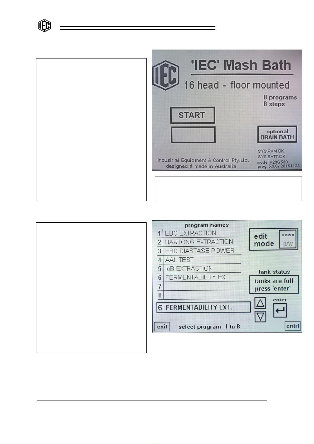
THE DISPLAY SCREENS:
The first display shows the model type and
program version number. The condition of
the RAM and the long life memory battery is
also displayed on this screen
On later models a button permits the
optional complete draining of the mash bath
before shutting down. When pressed the
bath drains empty and the alert beeper
sounds to advise the draining is complete.
Normally the power would then be turned
OFF. If START is pressed, the bath will
refill to prepare for the next mash..
Press START to enter the system. The
system provides 8 different programs and 8
steps inside each program.
.When START is pressed, if either the bath
or the distilled water tank is low in level,
they will both fill. A cycle cannot be started
until bath and tank are full.
From START to SELECTION
The list of programs shows and arrow
buttons permit selection. All programs may
be edited.
‘Tank Status’ advises if the bath and d/w
tank (floor models) are full. If bath or tank
is filling, operator cannot execute ENTER
to begin a program.
The p/w (password) button permits entry
into the EDITING areas where program
steps and program names can be created
or edited. A four digit password is required.
Initially use ‘1111’.
EXIT returns to the opening display and
CNTRL allows access to manual control of
the bath functions. ENTER is pressed to
begin a mash program.
‘OPENING’ display
‘SELECTION’ display
Screen shows “16 head - floor mounted” as the
selected model type, but information is valid for all
model types..

Mash Bath
I N D U S T R I A L E Q U I P M E N T & C O N T R O L P T Y . L T D .
6 1 - 6 5 M c C l u r e S t . T h o r n b u r y . 3 0 7 1 M e l b o u r n e . A u s t r a l i a
T e l : 6 1 ( 0 ) 3 9 4 9 7 2 5 5 5 F a x : 6 1 ( 0 ) 3 9 4 9 7 2 1 6 6
E m a i l : i e c @ i e c p l . c o m . a u
M A S H B - 2 0 1 9 0 3 1 4 . d o c 1 4 - M a r - 1 9
1 6
SELECTION to CNTRL: Provides manual
control of some of the bath functions. In
the case of a malfunction or an unwanted
noise, magnetic stirrers banks can be
turned off or be permitted to run.
Bath filling and draining can be controlled.
Momentary press on FILL cancels DRAIN
and momentary press on DRAIN cancels
FILL. Second press executes command.
By press button, bath can be forced to fill
beyond ‘full’ and will overflow to waste.
Bath circulation pump can be turned
ON/OFF but is normally free to run. The
machine STATUS is shown and the audible
volume of the various ALERTS can be
altered to suit lab. noise conditions.
Fault Alarms are always fixed at full
volume.
For testing equipment, the mash cycle can
be run with the heaters OFF.
‘CNTRL’ display
CNTRL to D/W CNTRL: (Floor models
only). D/W tank cannot be filled beyond
‘full’. Cooler (heat exchanger) is
automatic, but can be turned ON or OFF.
If forced ON, will turn OFF after 30 min to
conserve water. Can be set as a step
inside a program to begin cooling the tank.
Circulation and dispensing pump can be
turned ON/OFF. Dispense switch on gun
can be simulated by pressing button.
Programs carry d/w volumes, but a fixed
volume can be entered and, if turned ON,
this volume will always be the dispensed
volume. Normally remains OFF.
Tank status and several important notes.
D/W CONTROL & COOLING
For bench models, there is no distilled
water storage or dispensing.
Choice is to EXIT back to the SELECTION
display or to move on to the DIAG display.
NO DISTILLED WATER display
Mash Bath
I N D U S T R I A L E Q U I P M E N T & C O N T R O L P T Y . L T D .
6 1 - 6 5 M c C l u r e S t . T h o r n b u r y . 3 0 7 1 M e l b o u r n e . A u s t r a l i a
T e l : 6 1 ( 0 ) 3 9 4 9 7 2 5 5 5 F a x : 6 1 ( 0 ) 3 9 4 9 7 2 1 6 6
E m a i l : i e c @ i e c p l . c o m . a u
M A S H B - 2 0 1 9 0 3 1 4 . d o c 1 4 - M a r - 1 9
1 7
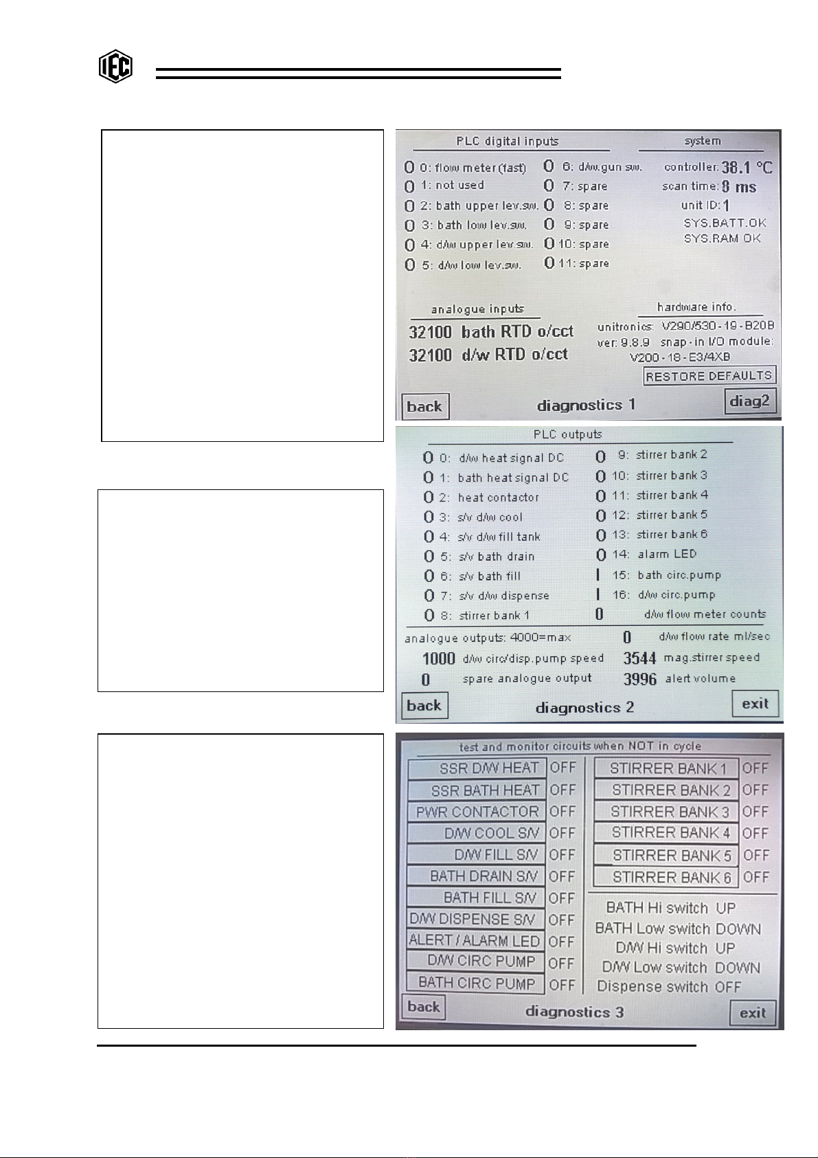
D/W CNTRL to DIAG: This display is
mainly for maintenance and fault finding.
PLC inputs status is displayed with values
of the controller’s internal temperature, the
temp.sensors, the scan time, RAM status
and battery status and ID info.is shown.
For bench models, the D/W RTD (temp.
sensor) value will show open circuit value
– but can be ignored.
If memory corruption should occur, if
‘RESTORE DEFAULTS’ is held depressed
(for 5 seconds) until the red LED comes
ON then OFF, the memory is re-loaded
with current data stored in a special area
of memory. This avoids keying in all the
program data again.
DIAGNOSTIC 1 display
DIAG to DIAG2: As above, this display is
for maintenance and fault finding. The
status of the PLC outputs is displayed
including the counts and flow rate from the
dispensing flow meter (floor models only).
The PLC drives the magnetic stirrers, the
alert beeper and d/w dispensing pump so
that each is adjustable. The value applied
to each device is monitored on this display.
4000 is the max value possible.
DIAGNOSTIC 2 display
DIAGNOSTIC 3 display
DIAG2 to DIAG3: As above, this display
is for maintenance and fault finding and it is
used when the bath is not in cycle.
Each rung of the display can be a press
button to force on each device. Other
rungs monitor most input devices. The UP
and DOWN status of the floats on the water
level switches is monitored.
If there is suspicion that a particular device
is not operating, it can easily be proven on
this screen. During manufacture it is used
as a check that each device is wired
correctly.
BACK will return you to the Diag 2 screen.
EXIT returns to the SELECTION display.

Mash Bath
I N D U S T R I A L E Q U I P M E N T & C O N T R O L P T Y . L T D .
6 1 - 6 5 M c C l u r e S t . T h o r n b u r y . 3 0 7 1 M e l b o u r n e . A u s t r a l i a
T e l : 6 1 ( 0 ) 3 9 4 9 7 2 5 5 5 F a x : 6 1 ( 0 ) 3 9 4 9 7 2 1 6 6
E m a i l : i e c @ i e c p l . c o m . a u
M A S H B - 2 0 1 9 0 3 1 4 . d o c 1 4 - M a r - 1 9
1 8
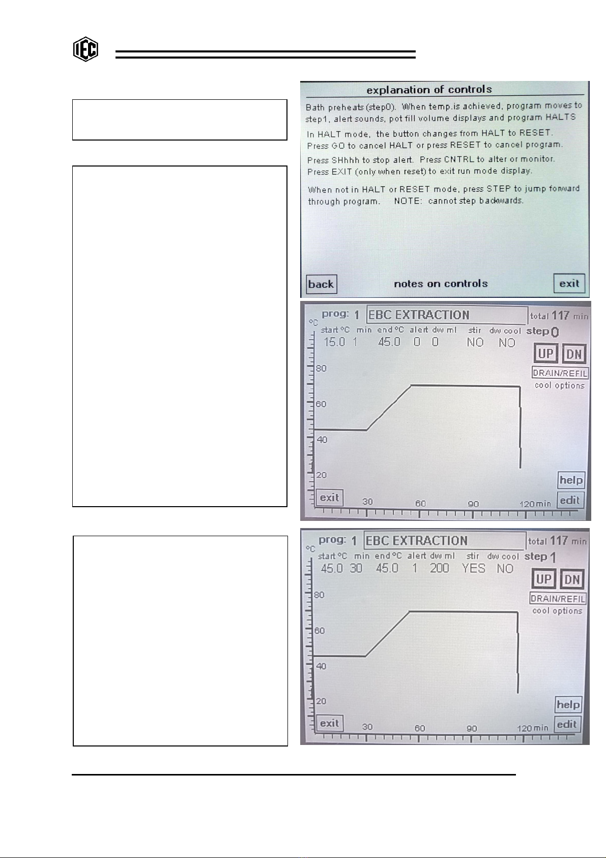
SELECT to ENTER: If the bath and d/w
tank are both full, the selected program
can be run. The graph displays to show the
temperature and time relationship for each
step.
Press GO to begin. Heaters come on and
‘H’ appears as heating monitor. If bath is
cooling, ‘C’ appears. Small square flashes
to monitor program running.
Step zero is the ‘pre-heat’ to 45
o
C. Stirrers
are normally off during pre-heat to avoid
fluffing the dry sample. When the short
time (1 minute) has expired AND bath initial
temperature is achieved, the program
jumps to Step#1 and HALTS. Stirrers
remain OFF and display shows the volume
of d/w to add to the sample. At this time,
alert#1 sounds for loading the pots with
distilled water. When pots are loaded, the
mash is about to start. Press GO to
release the HALT.
NOTE: When HALTED, the button
changes to RESET. If pressed, the
program resets and GO must be pressed
again. If a program needs to be RESET,
press HALT then press again to RESET –
otherwise press GO to cancel the HALT
and to continue.
For this particular program:
Step #1 starts at 45
o
C and remains 45
o
C
for 30 min.
Step #2 climbs a temperature ramp from
45
o
C to 70
o
C over 25 min. At the top of
the ramp, step #3 is triggered.
PROGRAM R
UN display
At the start of step #3, alert #2 sounds to call the operator to
add d/w to each mash pot. The volume to add (100 ml)
displays on the screen (see screen above at step #3). The
program does NOT automatically HALT at this point.
Step #3 runs for 60 minutes and holds 70
o
C.
…………………………………………………………
USEFUL OPTION: Pre-cool distilled water:
If it is required to cool the distilled water earlier than the END
of the mash cycle, an extra step (step #4) can be created at
say 50 minutes to maintain the 70
o
C and also COOL D/W
while the bath is holding the mash at 70
o
C (step#5) for the
extra 10 minutes. Then create step #6 to drop to 25
o
C for 1
minute so that heaters turn off immediately and the END of
cycle is reached and the slow “END alert” sounds during bath
draining.
……………………………………………………….
At the end of the 70
o
C period the next step (step#4) forces
the bath heaters off as the bath tries to cool from 70
o
to 25
o
in just one minute..
When step #5 is reached, the word END appears and the
beaker cooling cycle begins. This beaker cooling cycle can
be chosen during programming. In this case, the bath
automatically drains empty then re-fills again with cold water
to cool the samples quickly. The distilled water cooling coil
has water passing to cool down the D/W before the next
mash.
The samples are then removed and RESET is pressed.

Mash Bath
I N D U S T R I A L E Q U I P M E N T & C O N T R O L P T Y . L T D .
6 1 - 6 5 M c C l u r e S t . T h o r n b u r y . 3 0 7 1 M e l b o u r n e . A u s t r a l i a
T e l : 6 1 ( 0 ) 3 9 4 9 7 2 5 5 5 F a x : 6 1 ( 0 ) 3 9 4 9 7 2 1 6 6
E m a i l : i e c @ i e c p l . c o m . a u
M A S H B - 2 0 1 9 0 3 1 4 . d o c 1 4 - M a r - 1 9
1 9
PROGRAM RUN – NOTES…. continued………
As the program progresses, a vertical cursor or ‘time-line’ is seen to move from left to right
so that the current point on the graph can be seen. The program name, it’s number and
the step number are all displayed. The progressing time, the final temperature of that step
and the current bath temperature are all displayed on the screen. For floor models, the
distilled water temp. is displayed.
The program status is shown and this can be ‘RUNNING’ or ‘HALTED’ or ‘RESET’.
If an alarm occurs, this also is shown on the screen. An alarm can be bath ‘LEVEL LOW’ or
‘BATH TEMP o/c’ (temp.sensor open circuit). See later in manual for explanations.
The buttons have the following functions:
EXIT returns to SELECTION display when not in cycle. If in cycle, RESET must be pressed
before EXIT. . GO starts program and will always cancel HALT.
When program is RUNNING, the STEP button moves line forward to the start of the next
step of the program.
HALT will stop a program at any point. The stirrers stop and the timers stop but the bath
maintains current temperature. To cancel HALT, press GO. When HALTED, the HALT
button changes to RESET. If pressed, the program cancels. If cancelled accidentally, the
program can be continued by pressing GO, then STEP, then GO (to cancel the HALT),
then STEP to the closest place to resume cycle progress.
The Shhh button cancels the BEEPER at any time. If Shhh not pressed, the BEEPER self
cancels after 5 minutes running.
The INFO button provides 2 displays of brief information and CNTRL moves to the same
CNTRL and DIAG displays as described in previous pages.
First INFO display shows program status.
•Step number
•Time progress through whole
program
•Initial temperature
•Time progress through the step
•Final temperature
•Volume of d/w to add
•Stirring yes/no/intermittent/IoB
•Distilled water cooling
•Alert number (0 to 4)
•Selected cooling cycle at
program end
•Bath temperature
•Target temperature
•Distilled water temperature
INFO1 display
Mash Bath
I N D U S T R I A L E Q U I P M E N T & C O N T R O L P T Y . L T D .
6 1 - 6 5 M c C l u r e S t . T h o r n b u r y . 3 0 7 1 M e l b o u r n e . A u s t r a l i a
T e l : 6 1 ( 0 ) 3 9 4 9 7 2 5 5 5 F a x : 6 1 ( 0 ) 3 9 4 9 7 2 1 6 6
E m a i l : i e c @ i e c p l . c o m . a u
M A S H B - 2 0 1 9 0 3 1 4 . d o c 1 4 - M a r - 1 9
2 0
INFO2 display
This display contains notes to assist the
operator.
EXIT reverts to program run display.
EDIT PROGRAM display
Program is built from step0 up to final step
or END.
•On step0, start
o
C is 15
o.
. ‘min’ (time)
is 1 minute and “d/w ml” is zero. For
step0 these are fixed and cannot be
altered.
•Press “end
o
C” for keypad. Key in
desired end temperature for step0 (pre-
heat is usually to 45
o
).
•Press “alert” to cycle through the alert
options (0-4). Press HELP for
assistance.
•Press “stir” to cycle through the
options (NO/YES/INTERMITTENT). For
step0, stir is normally NO.
•Press below the arrows to cycle
through the cooling options. (WARM
BATH, SLOW COOL, DRAIN ONLY,
DRAIN / REFILL, DRAIN / REFILL
(twice), HOLD COOL). Press HELP
for assistance.
•Press HELP for useful information.
•Press EDIT for other program items
that can be edited. Press EXIT to
revert to the SELECTION display.
See next images showing steps 1, 2, 3, 4
and 5 of program #1.
STEP1:
•The “start
o
C” (45
o
C) is copied from the
“end
o
C” of the previous step. It cannot
be altered.
•Press “min” and set to 30. Press and
set “end
o
C” to be 45
o
C. This means
the temperature will remain steady at
45
o
C for 30 minutes.
•Set “alert” at the start of step1 at #1.
When pre-heat is finished, step1 is
entered and alert sounds. Programs
HALTS to load D/W into the pots.
•Press “d/w ml” to set the initial d/w fill
volume for the pots ( EBC is 200ml).
•Press ‘stir” to select YES so stirring
occurs when HALT is cancelled by GO.
STEP 1 display
Table of contents
Other IEC Laboratory Equipment manuals

Popular Laboratory Equipment manuals by other brands

RADWAG
RADWAG UYA 4Y PLUS Startup guide

Thermo Scientific
Thermo Scientific TSQ Quantum XLS Pre-installation requirements guide

Drucker Diagnostics
Drucker Diagnostics DASH Apex 24 Service manual

Beckman Coulter
Beckman Coulter CytoFLEX SRT Instructions for use

Qiagen
Qiagen EZ1 Advanced XL user manual

Metrohm
Metrohm 882 Compact IC plus manual


PI
PI Q-Motion Q-545 Series user manual

DIATECH PHARMACOGENETICS
DIATECH PHARMACOGENETICS EasyPGX qPCR instrument 96 user manual

Fluke
Fluke TIP900 operating instructions

AFi
AFi SS101 Assembly instructions

Hettich
Hettich MIKRO 185 operating manual

ATLAS BIOTECNOLOGIES
ATLAS BIOTECNOLOGIES AB2 instruction manual