manuals.online logo
Brands
  1. Home
  2. •
  3. Brands
  4. •
  5. APG
  6. •
  7. Measuring Instrument
  8. •
  9. APG RPX Series User manual

APG RPX Series User manual

RPX Continuous Level Probe
Installation Guide
For RPX Series
R
APG
Automation Products Group, Inc.
1025 W 1700 N Logan, UT 84321
www.apgsensors.com | phone: 888-525-7300 | email: [email protected]
Thank You
Thanks for purchasing an RPX resistive chain continuous level probe from us! We appreciate your
business and your trust. Please take a moment to familiarize yourself with the product and this
manual before installation. If you have any questions, at any time, don’t hesitate to call us at 888-
525-7300.
1. Description
2. How To Read Your Label
3. Warranty
4. Dimensions
5. Mounting and Installation
Instructions
6. Terminal Tables
7. Removal Instructions
8. Oset and Span Calibration
9. General Care
10. Repair Information
11. Hazardous Location Wiring
Table of Contents
5Mounting and Installation Instructions
Mounting Instructions:
• Flange Mounting: Provide the compatible mating ange on the tank and install using a
suitable gasket.
• Plug Mounting: Provide the compatible female boss on the tank and install the probe with
thread tape.
Additional care must be taken to ensure:
• The sensor is located away from strong magnetic elds, such as those produced by motors,
transformers, solenoid valves, etc.
• The medium is free from metallic substances and other foreign matter.
• The sensor is not exposed to excessive vibration.
Installation Notes:
• Do not locate your RPX series level sensor near inlets/outlets.
• If there is surface wave action, then use a time-delay relay or stilling tube. If a stilling tube is
used, drill vent holes in the tube and use a spacer to assure the oat has free travel inside the
tube (See Figure 5.1).
• The RPX can be mounted up to 20° from vertical.
4Dimensions
NOTE: Scan the QR code to the right to see the full
user manual on your tablet or smartphone. Or visit
www.apgsensors.com/support to nd it on our website.
Part # 200853
Doc # 9006503 Rev A
Each label comes with a full model number, a part number, and a serial number. The model
number for the RPX will look something like this:
The model number correlates with all the congurable options and tells you exactly what you have.
Compare the model number to the options on the datasheet to identify your exact conguration.
You can also call us with the model, part, or the serial number, and we can help you.
You’ll also nd all hazardous certication information on the label.
SAMPLE: RPX-A-P2W-S6-E-48.00
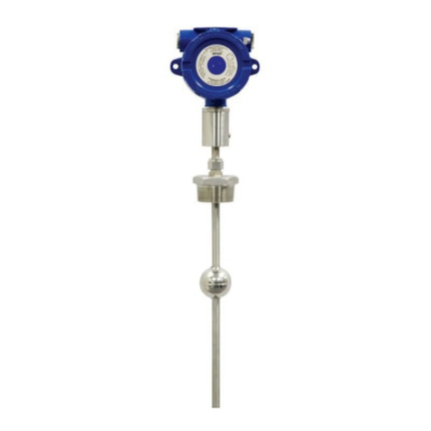
The RPX resistive probes contain reed switches in a 1/2” Ø stainless steel stem and a permanent
magnet in a oat. As the oat rises or falls with the level of the liquid, the magnet inside the oat
acts on the corresponding reed switches inside the stem, changing the output of the probe. The
RPX carries explosion proof, intrinsically safe, and non-incendive hazardous location approvals.
1Description
2How To Read Your Label
3Warranty
Figure 5.1
Stilling
Tube
Inflow Inflow
Spacer
20° 20°
20°
This product is covered by APG’s warranty to be free from defects in material and workmanship
under normal use and service of the product for 24 months. For a full explanation of our Warranty,
please visit https://www.apgsensors.com/about-us/terms-conditions. Contact Technical Support to
receive a Return Material Authorization before shipping your product back.
Scan the QR code below to read the full explanation of our Warranty on your tablet or smartphone.
Electrical Installation Instructions:
• Install conduit and/or cable with necessary seal(s) per Drawing 9001930 or 9001932 for
hazardous locations.
• Remove the housing cover.
• Check the Terminal Tables in section 6 before making any connections.
• Connect the wire for your system to the appropriate terminal.
• Replace the housing cover.
RPX Dimensions
DANGER: Do not remove the housing cover until the atmosphere
is determined safe, and the power supply is turned o.
6Terminal Tables
Terminals for RPX-A and RPX-I
White (Internal)
Black (Internal)
Red (Internal)
Output
Ground
VDC Supply
Black (Internal)
White (Internal)
Red (Internal)
Output
+24 VDC
Terminals for RPX-R (Resistive Output)
4.5”
114 mm
4.5”
114 mm
0.5”
13 mm
ML
S2
S1
IMPORTANT: Your RPX MUST be installed according to drawing
9001930 (IS Hazardous Installation Drawing For RPX) or 9001932
(Hazardous Mounting Drawing RPX) to meet listed approvals. Faulty
installation will invalidate all safety approvals and ratings.
DANGER: OPEN CIRCUIT BEFORE REMOVING COVER or KEEP COVER TIGHT
WHILE CIRCUITS ARE ALIVE;
AVERTISSEMENT -- COUPER LE COURANT AVANT D’ENLEVER LE COUVERCLE, ou
GARDER LE COUVERCLE FERME TANT QUE LES CIRCUITS SONT SOUS TENSION.
IMPORTANT: SEAL SHALL BE INSTALLED WITHIN 50 mm OF THE
ENCLOSURE;
IMPORTANT -- UNSCELLEMENT DOIT ETRE INSTALLE A MOINS DE 50 mm DU
BOITIER.
DANGER: EXPLOSION HAZARD-DO NOT DISCONNECT WHILE CIRCUIT IS LIVE
UNLESS AREA IS KNOWN TO BE NON-HAZARDOUS;
AVERTISSEMENT -- RISQUE D’EXPLOSION. NE PAS DEBRANCHER TANT QUE LE
CIRCUIT EST SOUS TENSION, A MOINS QU’IL NE S’AGISSE D’UN EMPLACEMENT
NON DANGEREUX.
WARNING: SUBSTITUTION OF COMPONENTS MAY IMPAIR INTRINSIC SAFETY;
AVERTISSEMENT -- LA SUBSTITUTION DE COMPOSANTS PEUT COMPROMETTRE
LA SECURITE INTRINSEQUE.
NOTE: This procedure can be performed in a non-hazardous area,
either prior to installation, or by temporarily uninstalling your 4-20
mA RPX probe.
7General Care
Your RPX resistive chain continuous level probe is very low maintenance and will need little care as
long as it is installed correctly. However, in general, you should:
• Periodically inspect the stem and oats for any trapped debris, sediment, or other foreign
material.
• Avoid applications for which the FLX was not designed, such as extreme temperatures,
contact with incompatible corrosive chemicals, or other damaging environments.
• If your RPX has an NPT mount, inspect the threads whenever you remove it from duty or
change its location.
• Never leave the housing cover o. If the cover is damaged or lost, order a replacement
immediately.
9
Removal Instructions
Removing your RPX from service must be done with care. It’s easy to create an unsafe situation,
or damage your sensor, if you are not careful to follow these guidelines:
• Ensure all circuts are de-energized, and any hazardous atmosphere has dispersed.
• Disconnect wires, either at terminals in the RPX head or at your system.
• Remove the RPX with an appropriately sized wrench (per your mounting type).
• Clean the RPX’s stem and oat of any debris (see General Care) and inspect for damage.
• Store your RPX in a dry place, at a temperature between -40° and 85°C (-40° and 185°F).
+24vdc
4 to 20ma Out
SPAN
OFFSET
RED BLK WH OUT 24V
Offset (4 mA)
Adjustment
Span (20 mA)
Adjustment
This procedure can be performed in a non-hazardous area, either prior to installation, or by
temporarily uninstalling your 4-20 mA RPX probe:
• Set DC power supply to 24 VDC, and connect to the RPX probe, with ammeter in loop.
• Move oat to the desired position for 4 mA output.
• Using a jeweler’s screwdriver or a suitable instrument, adjust the “Oset“ potentiometer until
you have a 4 mA output.
• Move oat to the desired positon for 20 mA output.
• Using a jeweler’s screwdriver or a suitable instrument, adjust the “Span“ potentiometer until
you have a 20 mA output.
• Repeat as necessary to ne tune calibration. (See Figure 8.1)
• Replace the housing cover when nished.
Oset and Span Calibration (4-20 mA output probes only)
8
Should your RPX require service, please contact us via email, phone, or online chat on our website.
We will issue you an RMA number with instructions.
• Phone: 888-525-7300
• Email: [email protected]
• Online chat at www.apgsensors.com
NOTE: You may also return the RPX probe to the factory for repair
and/or adjustment.
Repair Information
10
Figure 8.1
Hazardous Location Wiring
11
IS Hazardous Installation Drawing
Hazardous Mounting Drawing

This manual suits for next models

2

Other APG Measuring Instrument manuals

APG ACF-10 Series User manual

APG

APG ACF-10 Series User manual

APG MPI-E User manual

APG

APG MPI-E User manual

APG DST-2421 User manual

APG

APG DST-2421 User manual

APG PG10 User manual

APG

APG PG10 User manual

APG PG2 Series User manual

APG

APG PG2 Series User manual

APG PG-7 User manual

APG

APG PG-7 User manual

APG PG-5000 User manual

APG

APG PG-5000 User manual

APG PG5 User manual

APG

APG PG5 User manual

APG PG-2000 User manual

APG

APG PG-2000 User manual

Popular Measuring Instrument manuals by other brands

MPFiltri PML2 user guide

MPFiltri

MPFiltri PML2 user guide

Centech 92953 Operating information

Centech

Centech 92953 Operating information

Seres OL TOPAZ Total Hardness Operator's manual

Seres OL

Seres OL TOPAZ Total Hardness Operator's manual

Emtec BioProTT operating instructions

Emtec

Emtec BioProTT operating instructions

Accudata GVM-3 manual

Accudata

Accudata GVM-3 manual

iKonavs DRS manual

iKonavs

iKonavs DRS manual

Decagon DualHead Infiltrometer Operator's manual

Decagon

Decagon DualHead Infiltrometer Operator's manual

VOLTCRAFT SL-50 operating instructions

VOLTCRAFT

VOLTCRAFT SL-50 operating instructions

Siko SO100 User information

Siko

Siko SO100 User information

Runyon RHOPOINT METER instruction manual

Runyon

Runyon RHOPOINT METER instruction manual

JEWELL LILY user manual

JEWELL

JEWELL LILY user manual

Magnetrol Echotel 335 Installation and operating manual

Magnetrol

Magnetrol Echotel 335 Installation and operating manual

Extech Instruments AN100-NIST user manual

Extech Instruments

Extech Instruments AN100-NIST user manual

IFM DI5029 installation instructions

IFM

IFM DI5029 installation instructions

Kentucky MMP instruction manual

Kentucky

Kentucky MMP instruction manual

Amprobe MAN15 user manual

Amprobe

Amprobe MAN15 user manual

Cellbox Ground 2.0 Technical manual

Cellbox

Cellbox Ground 2.0 Technical manual

Valeport va500 operating manual

Valeport

Valeport va500 operating manual

manuals.online logo
manuals.online logoBrands
  • About & Mission
  • Contact us
  • Privacy Policy
  • Terms and Conditions

Copyright 2025 Manuals.Online. All Rights Reserved.