Emtec BioProTT User manual

BioProTTTM Flow Measurement System Version 1.00 page 1 of 75
Operating Instructions
BioProTTTM
Flow Measurement System
© em-tec GmbH
All rights reserved, especially with respect to reproduction, distribution and translation. These
Operating Instructions or any part thereof must not be reproduced, saved, processed, duplicated or
distributed without the written consent of em-tec GmbH.

BioProTTTM Flow Measurement System Version 1.00 page 2 of 75
Brief Operating Instructions - Quick Guide BioProTT™Flow Measurement System
Safety instructions
Chapter 2 - Page 6 ff.
Familiarize yourself with the safety instructions!
Setting up and connecting the flow meter
Chapter 6 - Page 15 ff.
Connect the BioProTT™ flow meter to power supply, e.g.
with supplied 24V DC power supply and connect analog or
digital interfaces as needed.
Installing flow sensor
Chapter 7 - Page 29 ff.
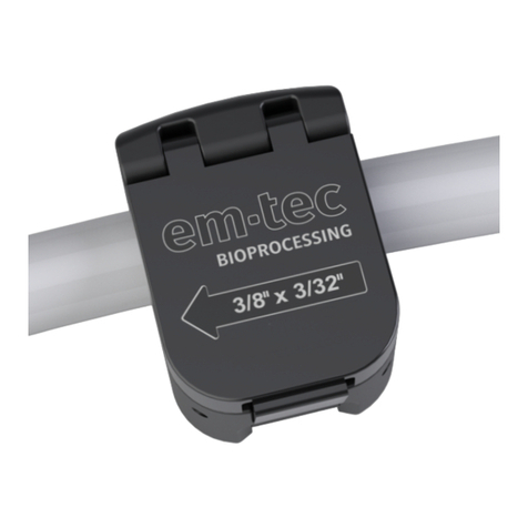
Connect Clamp-On Transducer to BioProTT™flow meter
by plugging it into the correct socket.
Please ensure that transducer is proper size for the tubing.
Insert tubing into BioProTT™ Clamp-On Transducer and
close lid. The flow direction is indicated with an arrow.
Prepare Measurement
Chapter 7 - Page 29 ff.
Power the BioProTT™ flow meter on and wait approx. 15s
for initialization.
Usually a sensor will show a flow value even with no flow
present. Zero this (flow value) offset by pressing the
appropriate button or selecting the appropriate menu option.
Note: ensure that
correct calibration table is selected (for sensors with
more than one table programmed)
tubing is filled with medium,
there is sufficient coupling and
the liquid in the tubing not moving (no flow) before
adjusting the zero offset (flow value ml/min!)
Perform custom calibration if necessary
Perform Measurement
Chapter 7.7 - Page 32 ff.
The BioProTT™ flow measurement system is now ready
for use.
Please note: If troubleshooting is necessary please see chapter TROUBLESHOOTING.

BioProTTTM Flow Measurement System Version 1.00 page 3 of 75
TABLE OF CONTENTS
1INTENDED USE.................................................................................................................................... 6
2GENERAL SAFETY AND IMPORTANT INFORMATION........................................................... 6
2.1 GENERAL SAFETY INFORMATION.................................................................................................... 6
2.2 GENERAL IMPORTANT INFORMATION ............................................................................................. 8
3SYMBOLS, UNITS AND ABBREVIATIONS.................................................................................... 9
3.1 SYMBOLS USED IN THESE OPERATING INSTRUCTIONS..................................................................... 9
3.2 SYMBOLS ON EXTERNAL POWER SUPPLY UNIT............................................................................... 9
3.3 SYMBOLS ON FLOW METER,SENSORS AND ON PACKAGING ......................................................... 10
3.4 UNITS............................................................................................................................................ 12
3.5 DEFINITIONS AND ABBREVIATIONS............................................................................................... 12
4DESCRIPTION OF MEASURING PRINCIPLE............................................................................. 13
5PACKAGING CONTENTS................................................................................................................ 14
6INITIAL SET UP................................................................................................................................. 16
6.1 BASIC CONSIDERATIONS AND POWERING OF FLOW METER AND 4-20 MACIRCUITS.................... 16
6.1.1 Wiring in “Active” Set-Up when Flow Meter is Not Relying on Current Loop Power........... 18
6.1.2 Wiring in “Passive” Set-Up when Powering Flow Meter via Current Loop .......................... 20
6.2 INSTALLATION AND OPERATION OF BIOPROTT™ FLOWTRACK................................................... 21
6.2.1 Front Panel BioProTT™ FlowTrack ...................................................................................... 21
6.2.2 Rear Panel BioProTT™ FlowTrack ........................................................................................ 22
6.2.2.1 Pin Assignment and Cable Colors for Round Connector for Digital Interface.............................. 23
6.2.2.2 Pin Assignment and Cable Colors for Round Connector for Power Analogue Flow and RSS
Interfaces 23
6.2.3 Connecting and powering up the system ................................................................................. 24
6.3 INSTALLATION AND OPERATION OF BIOPROTT™ FLOWTRACK DINRAIL NOTE:PRELIMINARY
INFORMATION!............................................................................................................................................ 25
6.4 INSTALLATION AND OPERATION OF BIOPROTT™ FLOWTRACK PLUS .......................................... 26
6.4.1 Front Panel BioProTT™ FlowTrack plus ............................................................................... 27
6.4.2 Menu Structure of BioProTT™ FlowTrack plus ..................................................................... 28
6.4.3 Rear Panel BioProTT™ FlowTrack plus ................................................................................ 29
6.4.4 Connecting and Powering up .................................................................................................. 29
6.5 MOUNTING.................................................................................................................................... 30
7PERFORMING MEASUREMENTS ON TUBING SYSTEMS USING BIOPROTTTM CLAMP-
ON TRANSDUCERS.................................................................................................................................... 31
7.1 INSTALLATION OF THE BIOPROTTTM CLAMP-ON TRANSDUCER ................................................. 31
7.2 CLAMPING ONTO TUBE................................................................................................................. 31
7.3 MEASUREMENT ACCURACY AND TUBE ARRANGEMENT............................................................... 32
7.4 RECEIVED SIGNAL STRENGTH (RSS /ACOUSTIC COUPLING)........................................................ 33
7.5 USE OF ACOUSTIC COUPLANT....................................................................................................... 33
7.6 ZERO ADJUSTMENT....................................................................................................................... 35
7.7 PERFORMING FLOW MEASUREMENTS ........................................................................................... 35
7.7.1 Measurement Using the Analog Interface of BioProTT™ FlowTrack, BioProTT™ FlowTrack
plus and BioProTT™ FlowTrack DINrail ............................................................................................. 35
7.7.1.1 Received Signal Strength (RSS / Acoustic Coupling)................................................................... 35
7.7.1.2 Flow Value.................................................................................................................................... 36
7.7.2 Measurement Using the Digital Interface (RS232) of the Different BioProTT™ Flow Meters
38
7.7.3 Measurements Using BioProTT™ FlowTrack plus................................................................. 41
7.7.3.1 Flow Value and Coupling ............................................................................................................. 41

BioProTTTM Flow Measurement System Version 1.00 page 4 of 75
7.7.3.2 Selection of Calibration Table....................................................................................................... 41
7.7.3.3 Selection of Calibration Factor...................................................................................................... 42
7.7.3.4 Adjustment of Brightness.............................................................................................................. 43
7.7.3.5 Totalizing...................................................................................................................................... 43
7.7.3.6 Status and Error Information......................................................................................................... 45
7.7.4 Custom Calibration Procedure................................................................................................ 45
8STATUS INFORMATION, TROUBLESHOOTING, SUPPORT AND SERVICE...................... 47
8.1 AVAILABLE STATUS CODES/INFORMATION FOR FLOW METER..................................................... 47
8.2 AVAILABLE ERROR CODES/INFORMATION FOR FLOW METER ...................................................... 48
8.3 TROUBLESHOOTING ...................................................................................................................... 50
8.4 CHECKING CURRENT LOOPS OF FLOW METER.............................................................................. 52
8.4.1 Method 1 –Using Power from Flow Meter and Measuring with Ampermeter ....................... 52
8.4.2 Method 2 –Providing Power Externally in Current Loop and Measuring with Ampermeter. 54
8.4.3 Method 3 –Checking Functionality with a Voltmeter............................................................. 55
8.5 RECOMMENDED PERIODIC CHECKS............................................................................................... 56
8.6 SUPPORT AND SERVICE ................................................................................................................. 57
8.6.1 Contact Information for Technical Support............................................................................. 57
8.6.2 Returns / RMA ......................................................................................................................... 58
9CLEANING, LOW LEVEL DISINFECTION AND MAINTENANCE......................................... 59
9.1 CLEANING OF THE BIOPROTTFLOW METER.............................................................................. 59
9.2 CLEANING AND DISINFECTION OF THE CLAMP-ON TRANSDUCER................................................. 60
10 APPROVAL INFORMATION........................................................................................................... 61
10.1CE MARK...................................................................................................................................... 61
10.2 ELECTRICAL SAFETY AND ELECTROMAGNETIC COMPATIBILITY................................................... 61
11 TECHNICAL DESCRIPTION........................................................................................................... 62
11.1 TECHNICAL DATA BIOPROTT™ FLOWTRACK /BIOPROTT™ FLOWTRACK PLUS ....................... 62
11.2 TECHNICAL DATA BIOPROTT™ CLAMP-ON TRANSDUCER.......................................................... 63
12 ENVIRONMENTAL PROTECTION AND DISPOSAL................................................................. 66
13 MANUFACTURER'S DECLARATIONS......................................................................................... 67
13.1 INFORMATION ON ACOUSTIC OUTPUT DATA................................................................................. 67
13.2 DECLARATION OF CONFORMITY ................................................................................................... 69
14 ORDERING INFORMATION FOR THE BIOPROTTTM FLOW MEASUREMENT SYSTEM
AND ACCESSORIES................................................................................................................................... 70
15 RETURN INFORMATION AND DECLARATION OF CONTAMINATION............................. 72
16 APPENDIX........................................................................................................................................... 74
16.1 CALIBRATION PROTOCOL FOR BIOPROTT™ CLAMP-ON TRANSDUCERS...................................... 74

BioProTTTM Flow Measurement System Version 1.00 page 5 of 75
Read these Operating Instructions carefully before starting up the
device!
Although the BioProTTTM flow measurement system represents state-of-the-art
technology, the user may be put at risk if the device is operated incorrectly. You should
therefore carefully read the Operating Instructions before use.
These instructions contain important information on the safe handling of the BioProTTTM
flow measurement system and accessories. Read these Operating Instructions carefully
before using the device and accessories, and keep them in an easily accessible location.
Familiarize yourself with and observe all warning and safety information.
It is the responsibility of the operator of the device to ensure it is used, inspected and
maintained in accordance with the Operating Instructions. Subsequent revisions or
instructions from the manufacturer must also be taken into account in this regard.
The manufacturer reserves the right to modify technical data without prior notice. Your
local distributor will supply you with current information and updates to these Operating
Instructions.
Please note:
When BioProTTTM is used in this manual, it usually refers to the complete flow
measurement system consisting of flow meter and Clamp-On Transducer.
There are 3 versions of the flow meter:
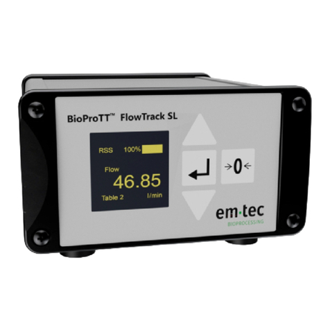
oBioProTT™ FlowTrack: flow meter without display in standard industry
housing.
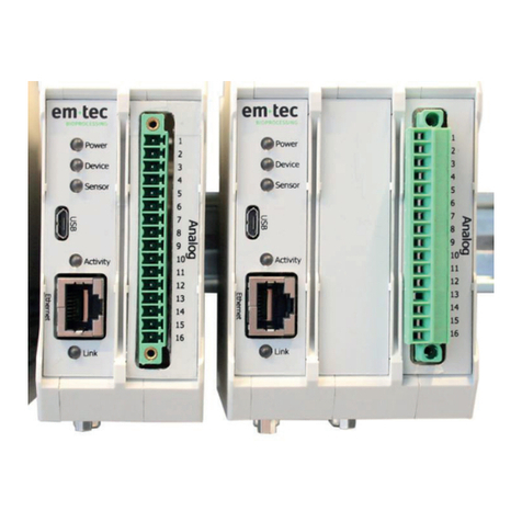
oBioProTT™ FlowTrack DINrail: flow meter without display for DIN rail
mounting.
Please note: this flow meter is not available yet
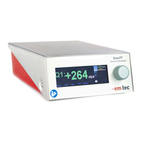
oBioProTT™ FlowTrack plus: flow meter with display and enhanced
functionality in standard industry housing
The differences of the flow meters (including SW features) will be pointed out in
the appropriate chapters.
This manual covers the following software versions of the BioProTTTM flow meter:
oFT_GFX_EV2200
The software version can be retrieved using the display or the digital
interface.

BioProTTTM Flow Measurement System Version 1.00 page 6 of 75
1Intended Use
If this device is not used as intended, the user may be exposed to
risks that were not taken into account during development.
The BioProTTTM flow measurement system is designed for non-invasive measurement
of volumetric flow of liquids. The measurement is based on the ultrasonic transit time
method. Usually used in laboratory, bioprocess and industrial processes.
2General Safety and Important Information
2.1 General Safety Information
Warning! The general safety information below must be observed
without fail to ensure safe handling of the device
Type of danger
Safety information
Risk of explosion
The BioProTTTM flow measurement system is not designed for use
in an explosive atmosphere or with explosive mediums. Take care
when using oxidants or flammable gases.
Risk to electrical
safety, or of
increased
electromagnetic
emissions or
lower resistance
of device to
interference
Use of accessories, power supply units, cables (lines) and sensors
other than those specified in these Operating Instructions is not
permitted.
Any external power supply that is not supplied with the system shall
have an output voltage of 24 V DC (±10%), must be current limited
to max. 6.25 A and continuously short circuit proof.
The device must not be used in residential areas.
Please ensure that all national requirements with respect to EMC
and electrical safety regulations are met when connecting a power
supply that was NOT originally shipped.
See chapter ELECTRICAL SAFETY AND ELECTROMAGNETIC
COMPATIBILITY; see chapter INITIAL SET UP

BioProTTTM Flow Measurement System Version 1.00 page 7 of 75
Type of danger
Safety information
Risk to safety due
to defective
device, applied
parts or
accessories
A defective device, sensors/parts or accessories must not be used
and must be replaced immediately. This applies in particular if the
cable insulation is damaged or if parts have broken off or are bent.
Electric shock
The power supply unit may not be immersed into liquids. However,
in the event of the ingress of liquid, pull out the power plug
immediately. Stop using the device and send it to our back for
inspection; see chapter RETURNS / RMA.
Malfunctions,
inaccurate
measured value
due to high-
frequency devices
The BioProTTTM flow measurement system may be influenced by
radio frequency (RF) devices. This includes mobile RF
communication equipment. Use of a RF device in the vicinity of the
BioProTTTM flow measurement system may also cause its
accessories to malfunction which may, among other things, lead to
measured values being provided inaccurately or incorrectly.
Overheating of
the device &
power supply
Prevent the device and power supply from being covered and direct
heat or sun radiation.
Faulty repairs
Repairs to the device shall only be carried out by authorized service
personnel. Unauthorized repairs will void manufacturer’s warranty.
Faulty electrical
installation
Comply with the installation requirements; refer to the chapter
ELECTRICAL SAFETY AND ELECTROMAGNETIC
COMPATIBILITY.
Measuring
inaccuracy,
Risk to electrical
safety
The measuring accuracy and safety-relevant aspects should be
checked at least every 2 years. Please refer to chapter
RECOMMENDED PERIODIC CHECKS for details
Risk of
infection/environ-
mental
contamination
due to improper
disposal
The device and accessories must be disposed of in accordance with
the national specifications for waste electrical and electronic
devices.
In case microbial contamination may be present on the device after
being used, we recommend you dispose of these separately in
accordance with the applicable regulations.
In case microbial contaminated, device or accessories shall be
cleaned and disinfected before they are sent to the manufacturer.
Do not return a device/sensor if you are not absolutely certain that
all traces of hazardous substances have been removed, e.g.
substances which have penetrated crevices or diffused through
plastic. Refer to chapter RETURN INFORMATION AND
DECLARATION OF CONTAMINATION for additional
information.
For more application-specific warnings, refer to the corresponding chapters.
The manufacturer only considers itself to be responsible for the safety, reliability and
usability of the device if:
The device is used in accordance with the instructions for use.

BioProTTTM Flow Measurement System Version 1.00 page 8 of 75
Installation, connection to the electricity supply and process control system,
additions, readjustments, changes or repairs and maintenance are only carried out
by qualified persons who have been authorized and trained. These qualified persons
must have read and understood this manual and must follow them accordingly.
The flow measurement system must be operated by persons authorized and trained
by the plant operator. Compliance with the instructions in this manual is
compulsory.
The manufacturer provides no warranty and assumes no liability in the event of non-
compliance with the above.
2.2 General Important Information
The following symbols are used in these Operating Instructions to highlight specific
information.
Caution! Important information regarding correct handling. To be
carried out and strictly observed!
If this following information is not observed, faults or damage to the
product or its surroundings may occur.
Type of damage
Important information
Electrical
malfunction or
irreparable
damage
The BioProTTTM flow measurement system is intended to be used
with its own power supply (shipped with the system) or e.g. within
electrical control cabinets with their own power supply.
The DC power supply line shall be shorter than 30 m and shall not
leave the building.
Damage due to
ultrasonic sound
At all device settings of the BioProTTTM flow measurement system
the Clamp-On Transducer generates ultrasonic sound only at a low
acoustic output level.
The ultrasonic sounds generated are harmless to persons, protein
solutions (e.g. blood, blood cells) and the environment according to
current knowledge, providing the system is used properly.
For more detailed information, see chapter INFORMATION ON
ACOUSTIC OUTPUT DATA.

BioProTTTM Flow Measurement System Version 1.00 page 9 of 75
3Symbols, Units and Abbreviations
All symbols and abbreviations used are explained in this chapter.
3.1 Symbols used in these Operating Instructions
The following symbols are used in these Operating Instructions to highlight specific
information.
Symbol
Meaning
Warning!
This safety symbol precedes critical information that must be strictly
observed in order to prevent injuries and fatal hazards. This warning
symbol is the most important safety symbol.
Caution!
Important information regarding correct handling. Must be performed
and strictly observed!
If this information is not observed, faults or damage to the product or
its surroundings may occur.
3.2 Symbols on External Power Supply Unit
Symbol
Meaning
Alternating current:
Alternating current must be fed to the supplied external power supply
unit. The values for the supply voltage must correspond to those of the
power supply unit: 100-240 VAC / 50-60 Hz.
Friwo Gerätebau GmbH (manufacturer)
Protection Class II (protective insulation)
As a safety guarantee, this power supply unit has additional insulation
to prevent dangerous touch voltage in the event of a fault. A PE
conductor must not be connected to this device.
IP40
Protected against access by wire
Do not dispose of this device as domestic waste!
Devices that have been placed on the market on or since 13.08.2005
must be disposed of as waste devices according to Directive
2002/96/EEC (WEEE) and national legislation.
CE marking: The external power supply unit satisfies the requirements
of Low Voltage Directive 2006/92 EC and EMC Directive 2004/108
EC.
UL test mark for recognized components for Canada and the USA by
Underwriter Laboratories Inc.

BioProTTTM Flow Measurement System Version 1.00 page 10 of 75
Symbol
Meaning
Direct current
(24 V DC from external power supply unit)
Caution
Further warnings and precautions exist.
(Refer to these instructions for use)
3.3 Symbols on Flow Meter, Sensors and on Packaging
Symbol
Meaning
Caution
Further warnings and precautions exist.
(Refer to these instructions for use)
IP65
Protected against dust and high pressure water jets / wash down from all
directions (BioProTT™FlowTrack, BioProTTFlowTrack plus,
BioProTT™ Clamp-On Transducer).
Please note: Unused connector sockets should be covered e.g. with the
provided flexible grip caps to avoid accumulation of dirt or any
potential short circuits.
IP20
Protected against access by finger (BioProTT™FlowTrack DINrail)
Direct current
(24 V DC from external power supply unit)
Do not dispose of this device as domestic waste!
Waste devices must be disposed of in accordance with Directive
2002/96/EEC and national legislation.
Manufacturer:
em-tec GmbH
Lerchenberg 20
86923 Finning
Germany
Serial number
Order number
CE marking: The device satisfies the requirements of EMC Directive
2004/108 EC

BioProTTTM Flow Measurement System Version 1.00 page 11 of 75
Symbol
Meaning
FCC-Mark that the United States Federal Communication Commission
authorized the device
Caution, fragile!
Handle with care!
Protect against moisture! Store in a dry place.
Temperature limit during storage
non-
condensing
Moisture limit during storage (non-condensing)
Air pressure limit
Storage
Transport

BioProTTTM Flow Measurement System Version 1.00 page 12 of 75
3.4 Units
Unit
Meaning
"
Tube size in inches, 1 inch ≈25.4 mm
ID" x WT"
Tube dimensions in inches:
Internal diameter ID x wall thickness WT
Outer diameter = internal diameter ID + 2 x wall thickness WT
3.5 Definitions and Abbreviations
Definitions,
Abbreviation
Meaning
CT / BCT
Clamp-On Transducer respectively BioProTTClamp-On Transducer
flow meter
BioProTT™ FlowTrack, BioProTTFlowTrack plus,
BioProTTFlowTrack DINrail
flow sensor
BioProTTClamp-On Transducer
PCS
Process Control System
ID
Inner diameter
OD
Outer diameter
TT
Transit-Time
RSS
Received Signal Strength which corresponds to the acoustic coupling
WT
Wall thickness

BioProTTTM Flow Measurement System Version 1.00 page 13 of 75
4Description of Measuring Principle
The physical measurement principles applied in the BioProTTTM flow measurement system
are described in this chapter.
The BioProTTTM flow measurement system uses the ultrasonic transit-time method (TT =
transit-time) which delivers precise flow values in tube systems and pipes.
The ultrasonic converters (piezoceramics) in the flow sensors transmit high-frequency
acoustic signals in and against the flow direction. The time difference between these
signals is proportional to the volumetric flow.
The basic principle is explained below.
Transmitter/
Receiver
Receiver/
Transmitter A
B
Tube
Flow
a
Figure 1: Principle of ultrasonic flow measurement (simplified using only two ceramics)
One piezoceramic (A) is excited by a set of high-frequency vibrations and transmits
ultrasonic waves to a second opposing piezoceramic (B) that acts as a receiver. The
piezoceramics are arranged at a specific angle α in relation to the flowing medium. The
transit time is influenced by the medium. The flow velocity of the medium can be
calculated using the measured transit time differences. The flow in litres per minute is
established using the known cross-section of the tube being scanned by ultrasonic
transmission.
Four ultrasound converters in a crosswise arrangement transmit high-frequency sound
signals alternately in and against the direction of the flow. The transit time for each
impulse is measured; the transit-time difference between the upstream and downstream
movement of the impulses is proportional to the volumetric flow.

BioProTTTM Flow Measurement System Version 1.00 page 14 of 75
5Packaging Contents
The BioProTTTM flow measurement system is shipped including the following
components:
Flow meter in either of the following variants:
oBioProTT™ FlowTrack (without display), or
oBioProTT™ FlowTrack plus (with display)
oBioProTT™ FlowTrack DINrail (without display for DIN rail mounting)
Please note: Flexible grip caps are provided for all sockets and should not be
removed until a socket is actually used to avoid any dirt accumulation or any
potential short circuits.
Power supply with country specific adaptor. Currently the following adaptors are
available: EURO, UK, USA/JAPAN, IEC - others on request.
Two (2) pre-configured 2 m long cables with plug on one end and terminal blocks on
other end.
One (1) pre-configured cable, 2 m long, for digital output with plug on one end and
standard female D-sub connector.

BioProTTTM Flow Measurement System Version 1.00 page 15 of 75
A male D-Sub to USB adapter for connection to standard USB ports.
Please download current driver from link specified on actual adapter labeling.
Terminal block adapter - BioProTT™ FlowTrack DINrail only
Extension cable for flow sensor in process control cabinet - BioProTT™ FlowTrack
DINrail only
Please note: a picture is not yet available
BioProTTTM Clamp-On Transducer.
The BioProTTTM Clamp-On Transducer is shipped pre calibrated and ready to be
connected to either of the flow meters.
Printed Manual.

BioProTTTM Flow Measurement System Version 1.00 page 16 of 75
6Initial Set Up
6.1 Basic Considerations and Powering of Flow Meter and 4-20 mA
Circuits
Generally, devices in 4-20 mA environments can be classified based on the current source
of the 4-20 mA loop as “active”or “passive”. Passive (or 2-wire) devices rely on loop
power, whereas active (or 4-wire) devices are providing power i.e. there is a separate
power supply for the device and the loop.
The BioProTT™ flow measurement system supports both modes of operation. However,
the flow meter always needs power to operate!
In a 2 wire environment with the DC power supply located e.g. at the process control the
flow meter and the current loop are powered via PCS.
Alternatively the flow meter (always requiring a power supply!) can also provide power to
the current loop.
4-20mA
1
Sensor
31 3 1 3 1 3
Power Flow RSS
sockets with pin numbers
4
2
BioProTT flow meter RSS +
socket -
Digital
Electronics 4
2
Flow +
socket -
PCS
-
+
+ -
+ 24V
4-20mA -
+
+ -
Socket sample
with pin assignment
RS 232
Power supply for flow meter
Flow and RSS current loops
incl. power supply
Figure 2: BioProTT flow meter schematics with focus on power supply
The figure above shows some of the electrical design which is important to properly wire
the system. The pin assignment corresponds to the pins as outlined the in following
chapters.

BioProTTTM Flow Measurement System Version 1.00 page 17 of 75
As discussed the flow meter needs power to operate, which can be provided:
With the power supply unit supplied with the flow meter (via power socket)
With another (different) external DC power supply
othis power source can be either the power source of the 4-20 mA loop
oor separate 24 V DC power supply
Please note:
When power is supplied via the power socket the on/off switch is used to power on the
flow meter otherwise the on/off switch does not have an effect
Ensure that there are no conflicting power sources/voltages applied to
Pin 1 and Pin 3 of either of the Power, Flow or RSS socket, as this they are internally
bridged between the sockets.
Below pin assignments and cable colors for round connectors for Power, Flow and RSS
sockets are shown (identical for all flow meter variants).
Figure 3: BioProTTflow meter rear view with one analogue plug connected -example w/ Flow socket
Figure 4: BioProTTview of power and analogue Flow and RSS socket
Pin No
Signal Power
Signal Flow/RSS
Wire color
(in supplied cabling)
1
24 V (24C_in)
24 V (24C_in)
Brown
2
Not assigned
Current Loop +
White
3
Ground in (GND_in)
Ground in (GND_in)
Blue

BioProTTTM Flow Measurement System Version 1.00 page 18 of 75
4
Not assigned
Current Loop -
Black
Details can be found in the following chapters.
6.1.1 Wiring in “Active” Set-Up when Flow Meter is Not Relying on
Current Loop Power
As discussed above, in an “active set-up” the device is not relying on current loop power,
instead the power supply used to power the device is also used to power the current loop.
This and the “active” wiring are shown in more detail below.
DC power can be supplied with the power supply unit shipped with the system. If this
power supply unit is not used, DC power can be supplied either through PIN 1/3 of the
Power, Flow or RSS socket using a compatible connector, e.g. from BINDER (part number
99 0079 100 04 - CIRCULAR, CONNECTOR, PLUG, 4POS).
This is e.g. useful, when connecting it to a process control and centrally powering the
devices on or off. In case power is provided via the Flow or RSS socket, the on/off button
is no longer “active”, i.e. the flow meter will start up as soon as power is available.
If power is supplied via the power socket please observe the on/off button.
The “active” set-up means that the power supply used to power the flow meter is also used
to power the current loop. To do so, a wire bridge is applied from Pin 1 to Pin 2 of the
Flow respective RSS cable.

BioProTTTM Flow Measurement System Version 1.00 page 19 of 75
For details see the circuit diagram below and observe the wiring instructions.
Figure 5: BioProTT flow meter rear view with one analogue plug connected -example w/ flow socket
Pin No
Flow / RSS
Wire color
(in supplied cabling)
Connected with
1
24 V (24C_in)
Brown
+ 24 V DC supply
2
Current Loop +
White
Connect Pin 1
with Pin 2
3
Ground in (GND_in)
Blue
Ground (GND) /
Return of PCS
4
Current Loop -
Black
Send (+) of PCS
Figure 6: Schematics - looking at pins of rear of flow meter of either Flow or RSS socket
Please note: the basic wiring diagram is identical to the “active” set-up, just the
power source is different.
3
4
2
1
PIN 1: +24 V
PIN 3: Ground (GND)
PIN 4: Current Loop (-)
PIN 2: Current Loop (+)
Return (-) Send(+)
of PCS
- +
+ -

BioProTTTM Flow Measurement System Version 1.00 page 20 of 75
6.1.2 Wiring in “Passive” Set-Up when Powering Flow Meter via
Current Loop
In a passive set-up, the current loop provides its own power as per definition. The power
from the current loop is then also used to operate the flow meter.
Since the flow meter always needs power to operate, you need to apply a logical “jumper”
to use the power from the current loop and provide it to the flow meter. This is explained
in detail below.
Figure 7: BioProTT flow meter rear view with one analogue plug connected -example w/ RSS socket
Pin No
Flow / RSS
Wire color
(in supplied cabling)
Connected with
1
24 V (24C_in)
Brown
Connect Pin 1 with Pin 2
Note: due to the wire bridge,
the flow meter is now powered
also!
2
Current Loop +
White
[see above]
3
Ground in
(GND_in)
Blue
Ground (GND) / Return of
PCS
4
Current Loop -
Black
Send (+) of PCS
Figure 8: Schematics - looking at pins of rear of flow meter of either Flow or RSS socket
Please note: only supply power to the flow meter via one of the sockets to avoid any
potential electrical problems. Either Flow or RSS socket pins can be used, when
power is supplied from the loop.
3
4
2
1
PIN 1: +24 V
PIN 3: Ground (GND)
PIN 4: Current Loop (-)
PIN 2: Current Loop (+)
Return (-) Send (+)
of PCS
Table of contents
Other Emtec Measuring Instrument manuals
Popular Measuring Instrument manuals by other brands

Trolex
Trolex XD One user manual

PCB Piezotronics
PCB Piezotronics X3501A2060KG Installation and operating manual
AXIOMA METERING UAB
AXIOMA METERING UAB QALCOSONIC E4 Technical operation guide
Extech Instruments
Extech Instruments MO55W user manual
Bushnell
Bushnell PRIME LP520KB manual
JB
JB DV-22N operating manual
