Aphex Studio Dominator 700 User manual

•
••
STUDIO DOMINATOR™
MODEL
700
~
_.... STUDIO DOMINATOR-'
...
'O'~'~'~
_ •
OPERA
TING
GUIDE
&
SERVICE
MANUAL
•

1.0
2.0
3.0
4.0
5.0
THE
STUDIO
DOMINATOR
TABLE
OF
CONTENTS
INTRODUCTION
FUNCTIONAL DESCRIPTION
2.1
2.2
2.3
2.4
2.5
2.6
2.7
Multi-Band
Processing
vs.
Wideband
ALT
(Auto
Limit
Threshold)
EQ,
Release
Time
and
TEC
The
Gain
Control
Circuits
The
Tracking
Control
Output
Ceiling
Control
Factory
Options
A DISCUSSION
of
GAIN REDUCTION
3.1
Leveling
3.2
Compression
3.3
Compression
Ratio
3.4
Operating
Threshold
3.5
Attack
and
Release
times
3.6
Limiters
and
Limiting
3.6.1
Program
Limiters
3.6.2
Peak
Limiters
3 . 7
Clippers
APPLICATIONS
4.1
4.2
4.3
4.4
4.5
4.6
Broadcast.ing
Recording
and
Mastering
Live
sound
Other
Applications
Use
with
the
COMPELLOR
Frequency
Response
Tailoring
INSTALLATION
5.1
Unpacking
5.2
Input
Sensitivity
Set
5.3
Mounting
5.4
Connectors
5.5
I/O
Considerations
5.5.1
Impedances
5.5.2
Balanced
vs.
Unbalanced
Operation
5.6
AC
Line
Connector
5.6.1
Voltage
Select.ion
5.6
. 2
Fuse
Selection
1
3
3
3
4
5
5
5
5
7
7
7
7
8
9
9
11
12
12
13
14
14
14
15
16
16
16
16
16
16
17

6.0
7.0
8.0
9.0
FRONT PANEL CONTROLS
6.1
Drive
6.2
Output
Ceiling
6.3
Secondary
Controls
6.3.1
LF
EQ
6.3.2
LF
X-over
6.3.3
HF
EQ
6.3.4
HF
X-over
6.3.5
Process
On-Off
6.3.6
Tracking
6.3.7
Release
Time
6.3.8
TEC
6.4
The
EO
Section
6.5
The
TEC
Function
FACTORY
OPTIONS
19
19
19
20
21
21
22
7.1
Model
702
-
With
Matrix/De-Matrix
22
7.2
Model
703
-
With
Pre/De-Emphasis
23
7.3
Model
704
-W/
Pre/De-Emphasis
and
Lowpass
Fltr
24
OPERATING
INSTRUCTIONS/SET-UP
8.1
8.2
8.3
8.4
8.5
8.6
8.7
Beginning
Drive
Output
Set
Drive
Set
Release
Time
TEC
Equalization
TECHNICAL
DESCRIPTION
9.1
Input
Circuit
9.2
Crossover
9.3
VCA
Limiters
9.4
Summing
Final
Limiter
9.5
Process
Sample
Rectifier
9.6
Output
Ceiling
circuit
9.7
Output
Line
Amplifier
9.8
Automatic
Limit
Threshold
(ALT)
circuit
9.9
Transient
Enhancement
Circuit
(TEC)
9.10
Metering
Circuit
26
26
26
26
27
27
28
28
29
29
29
30
31
31
31
32
32
32
32

10.0
TEST
PROCEDURES
10.1
Main
Board
10.2
Power/Metering
Board
11.0
BLOCK
DIAGRAM
12.0
SCHEMATICS
and
PARTS
LISTS
12.1
Input/Bandsplit/L1miters
and
Power
12.2
Summing/Peak
Ceiling/Output/TEC/ALT
13.0
EXPLODED
VIEW
and
MECHANICAL
PARTS
LISTS
14.0
SPECIFICATIONS
15.0
WARRANTY
and
SERVICE INFORMATION
16.0
APPLICATION
NOTES
33
33
36
38
40
Supply
41
43
45
48
49
50

Studio
Dominator
-
Owner's
Manual
1.0
INTRODUCTION
The
studio
Dominator
from
Aphex
Systems,
Ltd.
is
a
stereo
multiband
peak
limiter
designed
to
fit
a
wide
range
of
audio
aoplications.
~hrough
the
use
of
multiband
techniques
along
~~h
new
proprletary
circuits
the
audibility
of
limiting
action
has
been
greatly
reduced,
especially
when
compared
to
conventional
limiters.
This
means
that
greater
limiting
depth
is
possible,
resulting
in
higher
loudness
with
maintained
audio
quality.
At
virtually
any
limiting
depth,
the
Studio
Dominator
is
free
of
"hole
punching",
"dullness!I,
and
most
other
sound
deterioration
normally
associated
with
limiters.
As a
peak
overshoot
protection
limlter,
the
Studio
Dominator
is
undetectable
in
line
while
it
absolutely
prevents
peak
levels
from
exceeding
a
user
settable
output
level.
In
addition,
the
desired
limiting
effects
of
greater
audio
density,
increased
"punch",
etc.,
are
readily
available
with
the
Studio
Dominator.
The
Studio
Dominator
is
easy
to
adjust
and
use.
It
is
recommended,
however,
that
the
user
read
this
operating
manual
in
order
to
fully
understand
the
capabilities
of
the
device
and
how
to
best
set
up
for
operation.
The
Studio
Dominator
will
find
applications
in
all
parts
of
the
audio
industry.
Some
examples
are:
*
Sound
Contracting-
protection
of
amplifiers
and
speakers
from
overload;
increased
loudness;
maximized
use
of
avail-
able
power.
*
Recording
-
preventing
sudden
recorder;
tightening
tracks;
peak
overload
of
mixer
special
effects,
etc.
or
*
Digital
Sampling
-
Obtaining
good
full
scale
samples
free
from
peak
overload,
i.e
. ,
no
more
missed
samples.
*
Digital
recording
insuring
clean
recording
AID
clipping
of
peaks
and
overshoots.
*
Satellite
Uplink
Modulation
control
splattering
on
high
frequency
audio,
reduced
better
signal-to-noise
ratio.
by
stopping
to
prevent
distortion,
1

*
Broadcasting
-
AM
and
FM
Modulation
control
loudness;
cleaner
sound;
use
in
production
consistency
of
tapes,
punchier
voiceovers.
for
greater
tor
greater
*
Location
Film
Shoots
-
anti-crash
for
dialog
and
sound
effects
recording.
*
Post
Production
difficult
dialog;
Soundtrack
peak
control;
managing
controlling
transient
sound
effects.
*
Optical
Recording
-
preventing
"valve
clash"
with
higher
average
level
for
low
distortion
and
better
signal-to-no!se
performance.
*
Analog
Disk
Mastering
-
peak
control
for
higher
allowable
average
cutting
levels;
less
limiter
degradation
to
the
program;
brighter,
punchier
sound.
* C/D
Mastering
-
peak
and
density
control
for
more
accurate
digitizing,
cleaner
sound
requiring
less
error
correction
on
playback;
no
limiter
induced
sound
degradation.
2

2.0
FUNCTIONAL DESCRIPTION
Traditionally,
limiters
have
been
designed
specifically
for
a
particular
application,
or
with
a
mUltitude
of
interacting
controls
that
must
be
adjusted
to
adapt
the
unit
to
a
particular
purpose.
Because
the
Studio
Dominator
circuitry
is
"intelligent",
only
a
few
basic
adjustments
are
necessary
to
get
proper
results
in
any
application.
The
user
simply
sets
the
OUTPUT
CEILING
to
the
level
where
peaks
must
absolutely
stop
(such
as
100%
modulation
or
just
under
system
overload),
and
sets
the
DRIVE
control
to
obtain
the
desired
amount
of
limiting.
Some
additional
controls
are
provided,
but
they
are
mainly
for
those
who
wish
to
obtain
effects
from
the
limiter.
2.1
Multiband
vs.
Wideband
processing
Much
of
the
studio
Dominator's
high
performance
is
due
to
a
newly
created
multiband
processing
technique
that
overcomes
the
problems
previously
encountered
with
both
wide-
and
multi-band
limiting.
One
of
the
main
problems
of
wideband
limiting
is
"spectral
gain
intermodulation"
or
"hole
punching",
the
audible
effect
of
the
more
powerful
low
frequencies,
such
as
a
bass
drum,
causing
the
whole
program,
including
the
high
frequencies,
'to
drop
momentarily
in
level.
Wideband
limiters
also
tend
to
sound
dull
for
this
reason.
Multiband
limiting
attempts
to
solve
this
problem
by
splitting
the
audio
into
two
or
more
bands,
and
processing
them
separately.
But
more
bands
means
more
parameters
to
control
and
the
summing
of
the
separate
bands
to
deal
with.
For
a
three
band
limiter,
the
number
of
controls
could
easily
run
to
twelve
or
more
per
channel!
The
Studio
Dominator
uses
program
dependent,
II
intelligent"
circuits
to
eliminate
all
but
the
most
necessary
controls.
This
dynamic
control
also
tends
to
make
the
limiting
less
audible
by
providing
the
right
amount
of
processing
at
the
right
time.
2.2
ALT
(Automatic
Limit
Threshold)
Though
free
of
"hole
punching"
multiband
limiters
generally
do
not
keep
the
output
peak
amplitude
at
a
consistent
level.
This
is
due
to
the
varying
amount
of
band
energies
being
added
together
together
with
different
amounts
of
limiting
in
each
band.
Such
a
characteristic
is
usually
unacceptable
(at
least
in
broadcast
applications),
so
a
final
clipper
is
added
to
chop
down
the
final
level
to
a
reliable
amplitude
at
the
expense
of
added
distortion.
Another
solution
is
to
add
a
wideband
limiter
3

at
the
output,
but
that
only
re-introduces
wideband
limiting
and
negates
the
advantages
new
solution
had
to
be
found.
the
problems
of
of
multiband.
A
The
answer
is
a
new
circuit
concept
termed
ALT
(Automatic
Limit
Threshold,
Pat.
pending).
Incorporated
in
the
Studio
Dominator,
ALT
accurately
manages
output
summing
levels
in
a
way
that
produces
no
distortion
and
maintains
the
full
advantages
of
multiband
limiting.
In
the
ALT
system,
the
limiter
peak
output
is
co~stantly
monitored
and
adjusted
to
a
reference
level
by
controlling
the
limiter
thresholds.
Below-threshold
gain
is
not
changed,
so
low
level
signals
are
not
modified
by
the
ALT
process.
Since
ALT
has
a
finite
reaction
time,
a
soft
"catch
clipper"
is
used
following
the
final
summing
to
stop
any
brief
overshoot
transients.
This
does
not
produce
any
audible
distortion
because
the
ALT
prevents
all
but
the
briefest
overshoots,
too
short
to
hear.
By
these
methods,
the
summed
signal
peak
ceiling
is
guaranteed
to
remain
at
a
calibrated
value.
The
maximum
output
level
can
now
be
made
accurately
adjustable
by
a
single
front
panel
control.
This
is
a
highly
desirable
feature
not
commonly
found
on
limiters.
Due
to
intelligent
interplay
between
the
ALT
control,
the
attack
timing
of
the
individual
bands
and
the
catch
clipper,
the
"come
on"
of
the
limiter
is
extremely
smooth
sounding
if
it
can
be
heard
at
all.
2.3
EQ,
Release
Time
and
TEe
To
allow
for
variations
in
operating
conditions
and
tailoring
of
the
sound,
several
features
are
available
on
the
Studio
Dominator.
The
band
crossover
frequencies
are
selectable,
with
the
drive
levels
into
the
low
and
high
bands
adjustable
by
± 6dB.
This
allows
static
and
dynamic
equalization
effects
to
be
obtained.
As
the
bands
get
deeper
and
deeper
into
limiting,
the
EQ
effect
will
diminish
as
all
bands
approach
equal
amplitude.
The
release
time
allows
the
user
to
obtain
more
or
less
density
(loudness)
under
heavy
limiting.
A
quicker
release
time
gives
greater
loudness
by
maintaining
a
small
peak-to-average
ratio.
The
release
time
may
also
be
used
for
maximum
transparency
at
different
average
amounts
of
limiting.
All
limiters,
by
their
nature,
remove
transients
that
create
the
live
feel
in
audio.
A
unique
circuit
called
TEC
(Transient
Enhancement
Circuit,
Pat.
pending)
restores
some
of
4

this
transient
"feel".
Output
level
psychoacoustic
effect
is
accomplished
modification
of
the
components
below
switched
in
or
out
as
desired.
2.4
The
Gain
Control
Circuits
is
not
changed,
but
a
through
slight
envelope
threshold.
TEC
may
be
Extremely
low
distortion
limiting
is
accomplished
by
the
use
of
type
1537A
VCAs
in
each
band
coupled
with
individual
precision
comparator/pulse
charge
gain
control
circuits.
The
attack
time
is
sufficiently
fast
to
prevent
audible
overshoot
clipping
(with
the
help
of
ALT)
but
is
slow
enough
to
prevent
"hole
punching"
by
transients
such
as
record
pops,
etc.
The
limiting
thresholds
for
all
bands
are
equal
and
are
DC
programmed
by
the
ALT
bus.
Release
time
is
likewise
equal
and
DC
controlled.
2.5
Tracking
Control
TRACKING
locks
the
gain
control
signals
together
for
each
band.
This
provides
the
most
stable
stereo
image
.
However,
greatest
average
loudness
is
acheived
when
the
two
channels
are
operated
independently.
2.6
Output
Ceiling
Control
The
calibrated
OUTPUT
CEILING
control
is
the
only
control
on
the
studio
Dominator
that
is
not
a
DC
control.
It
is
a
precision
attenuator
that
is
adjustable
in
ldB
steps
from
-2dBU
to
+21dBU.
In-between
levels
can
be
accomplished
by
an
internal
trimpot
if
desired.
This
setting
represents
the
actual
peak
voltage
of
the
output
signal,
not
RMS
voltage.
This
limit
will
not
by
exceeded
under
ANY
conditions
of
limiting
.
The
RANGE
control
selects
HI
or
LOW
range
of
the
OUTPUT
CEILING
knob.
2.7
Factory
options
To
adapt
the
Studio
Dominator
to
the
widest
varjety
of
applications,
several
factory
options
are
available.
a)
Pre/De-emphasis
-
Allows
insertion
of
a
precise
preemphasis
curve
prior
to
limiting.
Oeemphasis
is
jumper
selectable
to
restore
flat
response
if
desired.
75
uSee
is
standard,
others
available.
b)
Lowpass
Filter
-
In
addition
to
the
above,
an
overshoot
corrected
lowpass
filter
of
exceptional
quality
may
be
installed
to
restrict
bandwidth
for
broadcast
or
digital
recording.
15kHz
is
standard.
5

c)
Matrix/Dematrlx
-
For
AM
stereo,
this
option
allows
L+R
and
L-R
limiting
with
selectable
de-matrixing.
These
options
are
available
as
factory
installed
only,
and
are
identified
by
separate
model
numbers.
Refer
to
Section
7.0
for
further
information.
6

3.0
A DISCUSSION
OF
GAIN REDUCTION
There
are
several
misunderstandings
about
limiting
and
compression
among
audio
professionals.
Compression
and
limiting
are
sometimes
referred
to
interchangeably,
for
example.
To
clearly
understand
the
operation
of
the
studio
Dominator,
it
is
good
to
have
a
standard
definition
of
terms,
and
have
a
clear
understanding
of
the
differences
between
leveling,
compression,
limiting,
and
clipping.
Therefore,
this
section
will
discuss
the
terminology,
offer
what
we
think
are
the
most
accurate
definitions,
and
describe
the
basic
principles.
3.1
Leveling
"Leveling",
or
AGC,
is
control
of
long-term
average
levels.
The
ratio
is
fairly
high
(>10:1),
with
slow
attack
and
release
times,
and
a
low
threshold.
Because
of
the
slow
operation,
leveling
has
little
or
no
effect
on
short-term
changes
in
average
level
or
on
transients.
3.2
Compression
and
Limiting
"Compression"
is
a
popular
contraction
of
the
general
term
"dynamic
range
compression",
where
"dynamic
range"
refers
to
the
difference
between
the
minimum
signal
level
and
the
maximum
signal
level
from
an
audio
source
over
a
period
of
time.
Limiting
may
be
defined
as
a
subset
of
compression
because
the
dynamic
range
is
reduced
through
limiting.
However,
because
there
are
significant
differences
between
what
are
called
"lim1
ters"
and
11
compressors"
,
it
is
best
not
to
equa
te
compression
and
limiting
in
application
oriented
thinking.
Compressors
are
used
principally
where
it
is
desired
to
force
an
audio
signal
to
maintain
a
more
constant
power
level.
This
may
be
to
improve
the
signal-to-noise
ratio
in
a
system,
to
correct
excessively
varying
volume
levels
from
a
program
source,
or
for
effects
like
gathering
greater
loudness.
One
way
to
think
of
this
is
that
compression
tries
to
keep
levels
from
falling
too
low.
Limiting,
in
contrast,
is
used
where
it
is
required
that
a
signal
be
stopped
from
exceeding
some
specific
level.
These
applications
include
prevention
of
overmodulation,
speaker
protection,
overcutting
protection,
system
overload
protection.
transient
peak
elimination,
etc.
.For
certain
applications
it
is
necessary
to
combine
a
compressor
and
a
limiter
to
get
the
desired
results.
This
might
be
where
we
are
required
to
maintain
a
high
average
signal
level
constantly
near
7

to
but
not
exceeding
the
system
overload
point.
an
example
of
this
application.
Broadcasting
is
The
parameters
which
mainly
differentiate
between
limiters
and
compressors
are:
compression
ratio,
operating
threshold,
and
timing.
The
circuits
to
create
both
types
of
processors
are
essentially
similar,
using
a
variable
gain
cell
and
a
detector
circuit
to
control
the
cell.
Only
the
above
parameters
need
be
changed
to
realize
either
a
limiter
or
compressor
from
such
a
circuit.
Changes
in
any
of
the
three
parameters
will
result
in
significant
sonic
differences.
Therefore,
there
is
not
only
a
science
to
designing
a
good
compressor
or
limiter,
but
a
good
measure
of
art
as
well.
It
is
important
for
the
user
to
appreciate
these
factors
because
he
plays
an
artistic
role
in
the
way
he
uses
and
adjusts
the
equipment.
3.3
Compression
Ratio
"Compression
ratio"
refers
to
the
ratio
of
a
decibel
change
of
input
level
to
the
corresponding
decibel
change
of
output
level
of
a
device.
Thus,
if
a
2dB
change
of
input
caused
a 1dB
change
of
output,
the
compression
ratio
would
be
2:1.
Perfect
linear
circuits
produce
a
1:1
compression
ratio.
Compressors
and
limiters
use
compression
ratios
ranging
from
about
1.1:1
to
about
30:1.
This
ratio
is
sometimes
referred
to
as
the
compression
"slope".
Variable
slope
compressors
are
available
which
begin
compressing
with
a
small
ratio
and
gain
ever
increasing
ratio
as
the
input
signal
rises
in
level.
Most
compressors
and
limiters
generate
a
more
or
less
constant
slope,
however.
In
general,
compressors
operate
with
low
ratios
of
1.1:1
to
3:1;
levelers
and
limiters
with
greater
ratios.
from
7:1
to
20:1.
3.4
Operating
Threshold
The
operating
threshold,
either
refered
to
as
the
"compression
threshold"
or
"limiting
threshold"
depending
on
the
processor,
is
the
input
referred
signal
level
where
dynamic
range
modification
begins
to
take
place.
All
limiters
and
most
compressors
operate
as
linear
amplifiers
with
a
relative
slope
of
1:1
below
this
threshold.
The
most
notable
exception
to
this
rule
is
a
compressor
associated
with
some
"companding"
noise
reduction
systems
where
the
compression
slope
begins
close
to
the
noise
floor
of
the
compressor
circuit.
That
is
to
say
that
constant
ratio
compression
takes
place
over
nearly
the
entire
dynamic
range
of
the
system.
In
all
other
compressors,
the
compression
threshold
is
a
user
variable
setting
which
determines
the
"depth"
of
compression
which
will
be
used.
The
lower
the
threshold
setting,
the
greater
amount
of
compression
is
obtained.
For
limiters,
the
limiting
threshold
is
also
a
user
adjustment.
8

The
Studio
Dominator,
rather
than
making
the
threshold
user
variable,
operates
with
a
self
controlled
threshold.
A
variable
input
gain
control
is
then
provided
to
adjust
the
"drive"
to
the
gain
controlling
and
detector
circuits,
allowing
the
Output
level
control
to
be
precisely
calibrated.
This
method
offers
the
advantage
of
optimized
noise
and
distortion
design
in
the
circuitry,
calibrated
output
level,
and
simplified
operation.
3.5
Attack
and
Release
Times'
Timing
parameters
are
extremely
critical
to
the
operation
of
limiters
and
compressors.
The
two
timing
factors
of
greatest
importance
are
attack
time
and
release
time
(sometimes
called
recovery
time).
The
attack
time
is
the
time
the
processor
requires
to
bring
the
input
signal
under
90%
control
after
the
input
level
exceeds
the
operating
threshold.
Limiters
usually
incorporate
fast
attack
times
to
prevent
sudden
signal
increases
from
escaping
amplitude
control.
Compressors
usually
incorporate
slower
attack
times
to
prevent
washing
out
of
transient
sounds.
Because
of
this,
compressors
will
generally
produce
overshoots
at
the
output
well
above
the
average
signal
level.
Often,
the
attack
time
is
not
adjustable
by
the
user,
and
thus
becomes
part
of
the
characteristic
sound
of
the
particular
model
of
compressor.
Release
time
is
the
time
required
by
the
processor
to
restore
itself
to
90%
of
full
gain
when
the
input
signal
drops
below
threshold.
This
time
can
vary
from
a
fraction
of
a
second
to
many
seconds
depending
on
the
particular
device.
Very
often
this
parameter
is
made
user
adjustable
both
for
limiters
and
compressors
even
if
the
attack
time
is
internally
fixed.
Longer
release
time
results
in
less
loudness
because
the
gain
does
not
restore
low
levels
quickly.
Faster
release
time
results
in
correspondingly
greater
loudness,
but
this
sometimes
comes
at
the
cost
of
greater
distortion
(especially
to
low
frequencies)
and
more
audibility
of
the
gain
control
effects.
3.6
Limiters
and
Limiting
As
previously
discussed,
in
order
to
be
effective,
a
limiter
typically
has
a
threshold
above
avo,
a
high
compression
ratio(7:1
or
greater),
and
fast
attack
and
release
times.
Compressors
usually
operate
at
much
lower
ratios
from,
say,
1.1:1
to
3:1
in
order
to
maintain
a
pleasing
sound
quality
because
gain
reduction
is
taking
place
over
a
larger
dynamic
range.
Compressors
operating
with
a
high
compression
ratio
are
mostly
used
when
a
sound
effect
is
intended.
Recording
engineers
may
use
a
heavily
driven
limiter
as
a
compressor
when
9

they
are
looking
for
more
"sustain"
for
example.
A
limiter
driven
effectively
becomes
a
compressor.
or
a
different
to
heavy
gain
"texture!!
J
reduction
Let
us
now
depart
from
further
elaborations
about
compressors,
and
focus
on
two
types
of
1
imi
teTS
:
tlpeak
1
imi
ters"
,
and
"program
1
imi
ters"
.
At
this
point
it
is
important
to
solidify
the
definition
of
"peak
level".
This
term
is
taken
to
mean
two
different
things
in
the
audio
industry.
Sometimes
it
is
used
to
refer
to
the
highest
(or
peak)
VU
level
occuring
in
an
audio
program.
Other
times
it
is
used
to
refer
to
the
actual
peak
amplitude
of
the
audio
wave,
which
would
be
measured
on
a
peak
program
meter
(ppm)
or
an
oscilloscope
display,
but
not
on
a
VU
meter.
Let
us
define
"peak
level"
as
the
true
peak
waveform
amplitude,
and
"peak
program"
as
the
highest
VU
level.
3.6.1
Program
Limiters
With
these
definitions
in
mind,
a
"program
limiter"
can
be
described
as
a
limiter
having
all
the
previously
defined
characteristics
of
a
limiter,
and
whose
detection
circuits
result
in
limiting
the
"peak
program"
level
(as
measured
on
a
VU
meter)
to
a
specified
level,
usually
zero
VU,
without
regard
for
the
peak
level
.
3.6.2
Peak
Limiters
A
"peak
limiter"
is
used
where
the
absolute
audio
waveform
amplitude
cannot
be
allowed
to
exceed
a
given
value.
Most
audio
systems
produce
particularly
objectionable
distortion
when
driven
to
overload,
so
peak
limiters
are
often
used
to
maintain
safe
peak
levels
below
any
system
clipping
to
guarantee
a
distortion
free
system.
Limiters
in
this
application
are
sometimes
referred
to
as
"protection
limiters".
Another
appl
ication
of
peak
1imi
ters
is
"modulation
limi
ting
"
in
a
broadcast
situation
where
a
specified
peak
level
is
defined
as
100
percent
modulation
which
must
not
be
exceeded.
Peak
limiters
are
usually
characterized
by
fast
attack
and
release
times,
a
very
high
compression
ratio
and
a
high
threshold
such
that
no
gain
reduction
takes
place
for
signals
whose
peak
level
is
under
the
overload
point
of
the
system.
Limiters
wlth
very
fast
release
tend
to
generate
distortion
under
continuous
gain
reduction,
but
for
protection
limiting
where
limiting
is
brief,
the
fast
action
tends
to
be
practically
unnoticeable,
maintaining
a
clean
sounding
audio
system.
10

3.7
Clippers
Most
peak
limiters
incorporate
a
final
clipper
to
catch
any
amplitude
overshoot
that
may
escape
the
variable
gain
element
due
to
the
short
but
finite
attack
time
of
the
detector
circuit.
A
properly
designed
clipper
has
a
virtually
instantaneous
action
to
catch
the
briefest
of
transients.
This
"catch
clipper"
usually
has
little
work
to
do,
and
because
it
clips
only
brief
transients
is
inaudible
in
the
circuit.
Clipping
is
for
protection,
and
performs
no
audible
gain
reduction.
At
this
polnt,
the
reader
should
be
well
aware
of
the
differences
between
limiters
and
compressors,
and
how
they
might
be
used.
1 1

4.0
APPLICATIONS
*
*
*
'"
*
*
*
*
*
Some common
applications
of
limiters
are:
Obtaining
more
loudness
Obtaining
more
"punch"
Preventing
transmitter
overmodulation
Preventing
tape
overload
Preventing
system
peak
overload
Preventing
overcutting
Preventing
satellite
uplink
overmodulation
Audio
P.A.
system
protection
Special
Effects
Conventional
limiters
are
more
suited
to
certain
of
these
uses
than
to
others.
The
Studio
Dominator,
because
of
its
intelligent
circuitry
and
optional
configurations,
is
equally
well
suited
to
all
limiter
uses.
This
manual
will
address
several
general
categories
of
limiter
application
and
show
typical
setups
which
can
serve
as
the
basis
for
your
particular
operation.
4.1
Broadcasting
FM
broadcast
processing
requires
special
consideration
because
of
the
pre-emphasis
curve
and
bandwidth
restrictions
involved.
An
option
card
(and
a
few
other
simple
modifications)
can
be
installed
in
the
Studio
Dominator
to
produce
accurate
operation
for
FM
transmission.
With
this
option,
two
operating
conditions
may
be
chosen.
First,
pre-emphasis
can
be
selected
which
causes
the
studio
Dominator
to
output
a
properly
pre-emphasized
signal
ready
for
direct
feed
into
a
non
pre-emphasized
stereo
generator.
This
is
the
preferred
approach
in
most
cases.
Second,
accurate
de-emphasis
may
be
selected
after
limiting
to
restore
flat
system
response
for
feed
to
a
pre-emphasized
stereo
generator.
NOTE:
If
the
stereo
generator
used
does
not
include
the
necessary
left
and
right
channel
15kHz
overshoot
compensated
lowpass
filters,
then
the
lowpass
filter
option
should
be
specified
in
the
Studio
Dominator.
Many
stereo
generators
include
lowpass
filters.
but
they
are
not
overshoot
compensated,
which
results
in
loss
of
modulation
capability.
In
this
case,
the
filter
should
be
bypassed
or
removed
and
the
studio
Dominator
filter
used.
Setting
up
the
limiter
for
FM
operation
is
basically
similar
to
the
general
set-up
procedure.
A
program
signal
is
fed
into
the
studio
Dominator
and
drive
is
adjusted
to
produce
at
least
BdB
of
limitng.
Release
time
should
be
full
fast
12

initially.
Raise
the
peak
ceiling
control
to
approach
100
percent
modulation
on
program
peaks.
The
output
control
operates
in
IdB
steps
so
it
will
probably
be
necessary
to
use
the
stereo
generator
input
trimmers
to
achieve
the
final
exact
100
percent
modulation
setting.
If
there
are
no
such
trimmers
on
your
stereo
generator,
you
may
access
the
output
trimmers
inside
the
Studio
Dominator
for
a
fine
adjustment
of
output
level.
Once
the
modulation
limits
are
set
by
the
above
technique,
the
DRIVE, RELEASE TIME,
and
other
controls
may
be
adjusted
to
obtain
the
desired
on-air
sound.
Use
of
the
TEe
may
be
particularly
beneficial
since
a
greater
sense
of
transient
dynamics
can
be
obtained.
Additionally,
by
not
turning
on
the
tracking
mode,
wider
stereo
imaging
and
higher
average
loudness
can
be
obtained.
The
loss
of
center
image
stability
is
not
as
severe
with
the
Studio
Dominator
as
expected
because
the
ALT
circuit
intelligently
tracks
the
limiting
thresholds
of
left
and
right
channels.
4.2
Recording
and
Mastering
a)
Tracking
If
the
tape
saturates,
if
the
electronics
run
out
of
he~droom,
or
if
the
digital
recorder
reaches
peak
input,
-
you
can
no
longer
"fix
it
in
the
mix."
By
setting
the
Studio
Dominator
output
ceiling
just
below
the
system's
peak
level,
these
problems
will
never
again
occur.
Recording
with
boosted
high
end
can
be
safely
handled
by
the
Studio
Dominator,
preventing
tape
saturation
while
eliminating
the
need
for
another
equalizer
in
the
signal
path.
Using
the
Studio
Dominator.
the
output
of
the
mic
preamp
or
input
fader
may
be
increased
to
make
a
"hotter"
recording.
This
will
effectively
increase
the
signal-to-noise
performance
so
that
noise
reduction
may
no
longer
be
necessary.
b)
Mixing
Very
often
it
is
desired
that
a
lead
track
ride
out
front
of
the
rest
of
the
mix.
By
using
the
studio
Dominator
on
that
track.
maximum
loudness
can
be
achieved
and
maintained,
allowing
it
to
stay
out
front
without
having
to
drop
the
level
of
the
rest
of
the
mix.
Since
the
ratio
of
the
Studio
Dominator
is
infinite,
any
track
driven
into
consistent
deep
limiting
will
not
move,
regardless
of
input
level.
This
is
especially
useful
for
bass.
13

c)
Mastering
The
ideal
for
mastering
is
an
invisible
transfer
from
tape
to
lacquer
at
the
maximum
level
possible.
When
using
a
conventional
limiter
to
prevent
overcutting,
the
bass
or
kickdrum
modulates
the
high
end,
causing
"holes"
and
loss
of
transient
1!feel".
If
the
lead
track
is
very
transient,
the
whole
mix
may
"duck"
during
peaks.
Due
to
its
multiband
technology
and
intelligent
control
circuits,
the
Studio
Dominator
will
not
cause
these
effects.
At
the
same
time,
a
higher
level
disc
may
be
safely
cut
with
more
predictable
groove
spacing.
4.3
Live
Sound
As
with
recording
electronics,
P.A.
equipment
has
headroom
limitations.
Although
power
amps
amd
speakers
may
be
more
forgiving
than
digital
audio
to
short
term
peaks,
various
types
of
audible,
objectionable
distortion
may
be
generated.
Furthermore,
the
amps
and
speakers
themselves
may
be
driven
to
failure.
The
studio
Dominator
not
only
prevents
system
overload
while
maintaining
audio
quality,
but
actually
improves
overall
system
performance.
It
does
this
by
enabling
all
parts
of
the
sound
system
to
safely
run
at
their
maximum
operating
levels,
continuously.
A
great
increase
in
effeciency
may
be
realized
now
that
headroom
is
no
longer
such
a
consideration.
Stage
monitors
always
demand
maximum
controlled
loudness.
The
Studio
Dominator's
limiting,
crossover
and
EQ
controls
allow
precise
tailoring
of
the
sound
for
maximum
level
before
feedback.
4.4
Other
Applications
Once
the
characteristics
of
the
Studio
Dominator
are
understood,
other
applications
become
obvious,
such
as
-
*
Film
and
Video
post-production-
The
limited
dynamic
range
and
unpleasant
sound
of
overmodulation
in
these
media
make
the
Studio
Dominator
an
essential
tool
in
any
post
house.
*
Tape
Duplication-
Master
tapes
can
be
recorded
at
a
higher
level,
making
the
dupes
"hotter\!
with
lower
noise
and
transient
distortion.
*
Satellite
Transmission
-
Signal-to-noise
ratio
can
be
improved,
and
pre-emphasis
induced
high
frequency
modulation
distortion
avoided.
Overshoots
from
companding
can
be
reducede
for
greater
channel
modulation
and
lower
distortion.
14

*
Digital
Sampling
for
synthesizers
-
Very
transient
acoustic
sounds
can
be
properly
sampled
without
worrying
about
sampler
drive
levels.
4.5
Use
with
the
Aphex
Compellor
(Compressor/Leveler)
As
previously
described,
compressors
bring
low
signals
up,
and
limiters
hold
high
level
or
peak
signals
Using
both
devices
in
series
gives
you
both
control
of
levels
(compression)
and
peak
control
(limiting).
level
down.
average
Since
the
Compel
lor
is
the
most
transparent
compressor/leveler
and
the
Studio
Dominator
the
most
effective,
flexible
and
transparent
peak
processor,
the
combination
of
the
two
devices
is
the
ultimate
in
dynamics
control.
4.6
Frequency
Response
Tailoring
As
program
audio
reaches
the
onset
of
limiting,
low
frequencies
tend
to
be
limited
first,
due
to
their
greater
energy.
The
end
result
is
a
slight
perception
of
"brightening"
the
sound,
enhancing
impact
and
transient
feel
of
percussive
sounds
as
well
as
aiding
intelligibility
in
most
applications.
In
the
event
that
absolute
flatness
of
"dynamic"
frequency
response
15
desired,
a
pre-
and
de-emphasis
card
may
be
added
to
tailor
the
limiting
curve
as
needed.
See
section
7.0
for
more
information
on
factory
options.
15

5.0
INSTALLATION
5.1
Unpacking
Your
Studio
Dominator
was
carefully
packed
at
the
factory,
and
the
container
was
designed
to
protect
the
unit
from
rough
handling.
Nevertheless,
we
recommend
careful
examination
of
the
shipping
carton
and
its
contents
for
any
sign
of
physical
damage
which
could
have
occured
in
transit.
If
damage
is
evident,
do
not
destroy
the
container
or
packing
material.
Immediately
notify
the
carrier
of
a
possible
claim
for
damage.
Shipping
claims
must
be
made
by
the
consignee.
5.2
Input
Sensitivity
Set
Before
installation
the
Studio
Dominator
must
be
set
for
the
correct
input
sensitivity
corresponding
to
the
desired
operating
level
(OVU).
It
may
be
set
to
either
-10
or
+4 dBm.
The
switch
for
each
channel
'
is
located
inside
the
unit
just
behind
the
input
jacks
on
the
main
PC
board.
Simply
slide
the
switch
to
the
desired
position.
Towards
the
power
supply
is
+4dBm,
away
is
-10dBm.
The
+4dBm
position
is
suitable
for
operating
levels
from
0
to
+lOdBm.
5.3
Mounting
The
Studio
Dominator
occupies
one
standard
rack
unit
of
space
(1
3/4")
19
rr
wide,
with
a
depth
of
8
1/2rr.
Allow
at
least
an
additional
3"
of
depth
for
connectors.
Be
sure
that
there
is
at
least
1/2"
of
air
space
around
the
unit
for
cooling.
Mount
with
the
cushioned
rack
screws
provided.
5.4
Connectors
The
audio
inputs
and
outputs
are
made
with
standard
XLR
type
3-pin
connectors
on
the
rear
panel.
Equal
phase
is
maintained
from
input
to
output,
so
the
user
may
elect
to
use
either
pin
2
or
pin
3
as
high
to
match
his
balanced
system.
5.5
I/O
Considerations
5.5.1
Impedances
The
input
is
of
high
(160
kOhms)
impedance
and
may
be
easily
driven
by
any
output
source.
In
the
case
of
certain
situations
that
need
to
see
a
600
Ohm
load,
a
600
ohm
resistor
may
be
tied
across
pins
2
and
3
on
the
input
16
Table of contents
Other Aphex Recording Equipment manuals
Aphex
Aphex EXCITER User manual

Aphex
Aphex 2020 MkIII User manual

Aphex
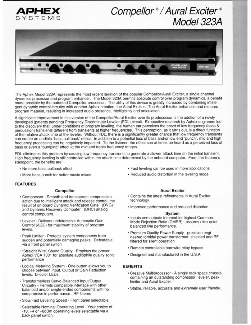
Aphex Compellor/Aural Exciter 323A Installation and operation manual

Aphex
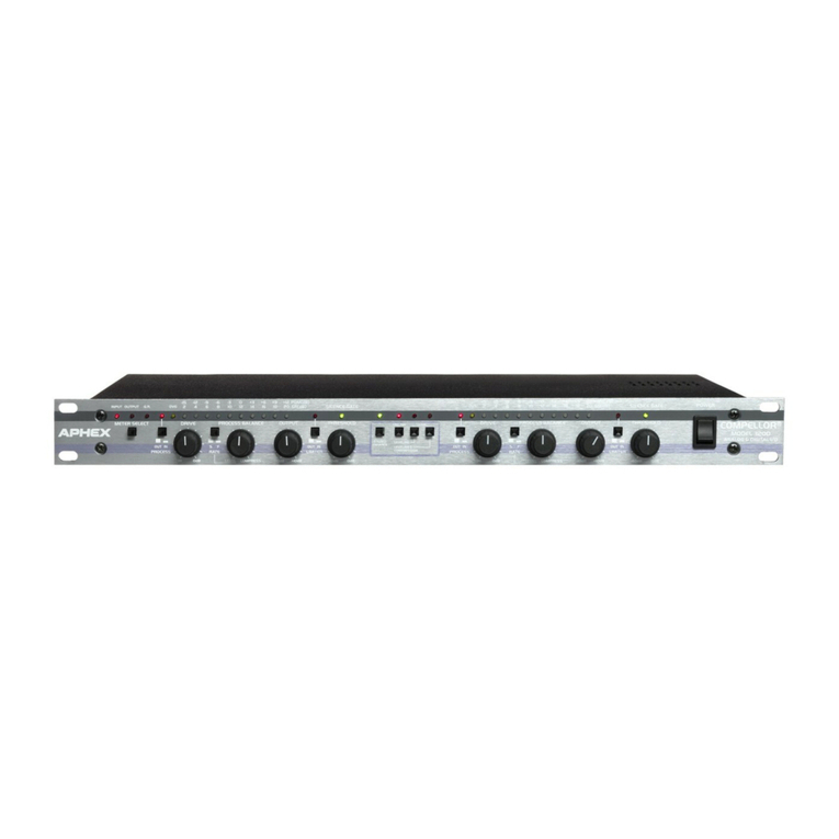
Aphex Compellor 320D User manual

Aphex
Aphex Anaconda User manual

Aphex
Aphex 5200 User manual
Aphex
Aphex EX-BB 500 User manual

Aphex
Aphex 228 User manual

Aphex
Aphex Compellor 320D User manual
Aphex
Aphex EQF 500 User manual