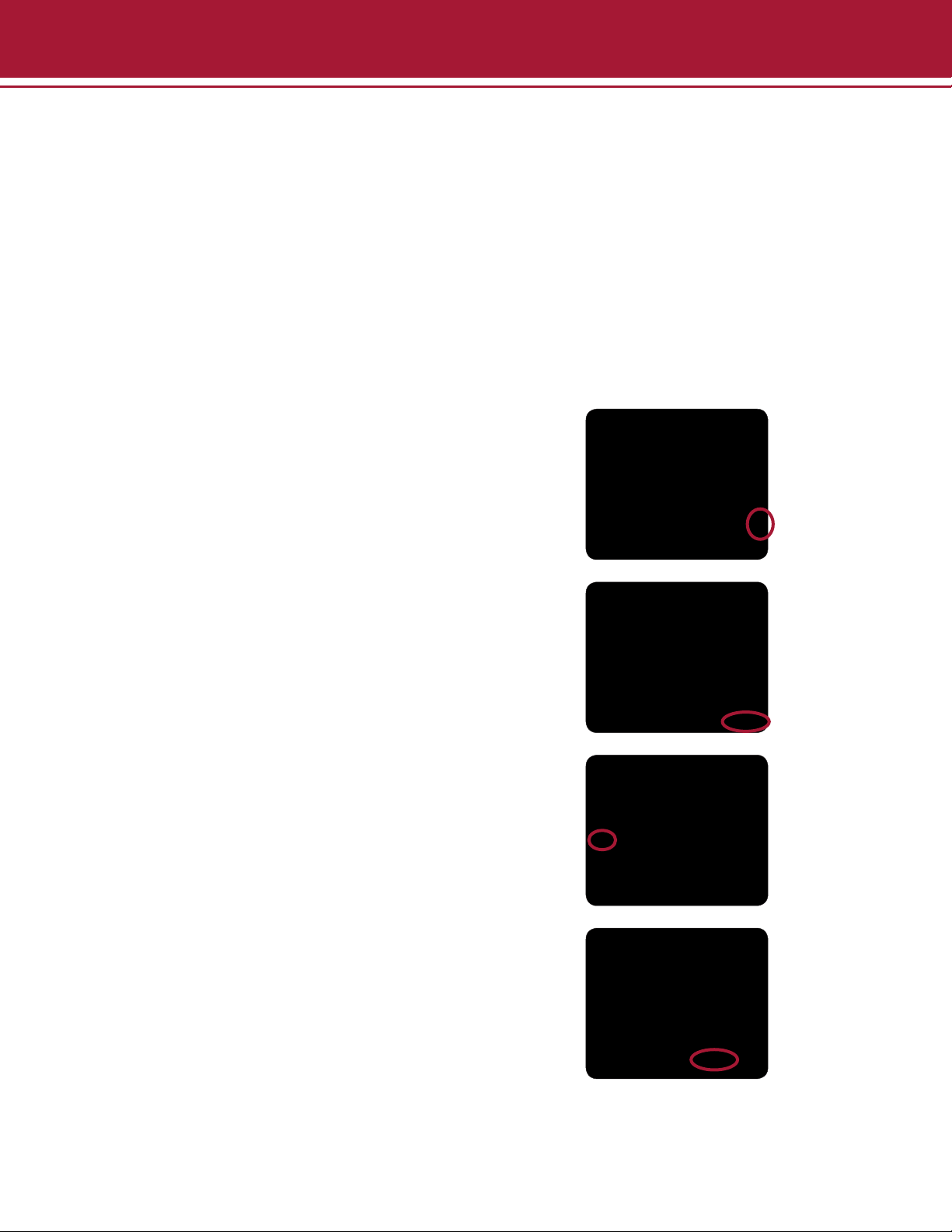
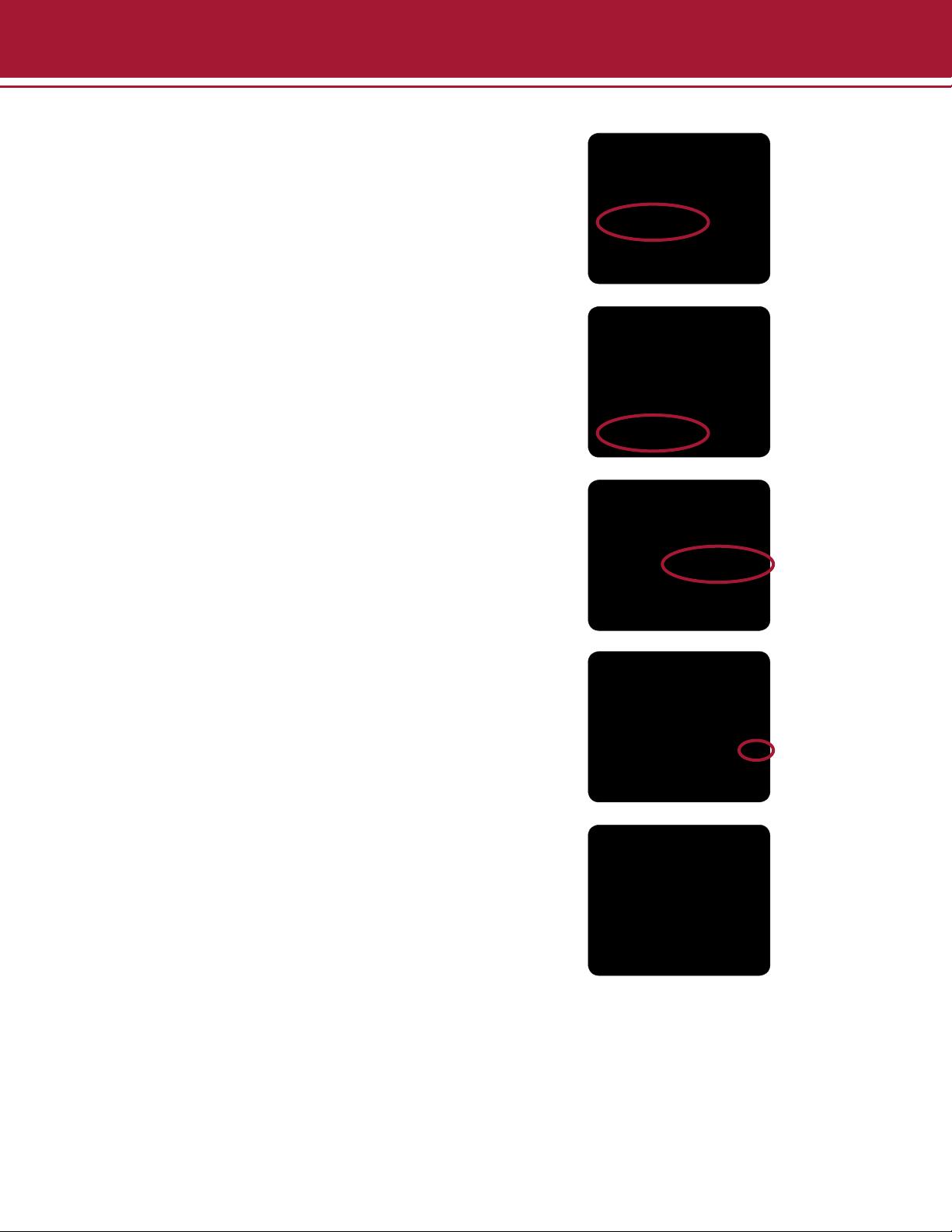
aplegen Omega Fluor User manual

Omega Fluor™and
Omega Fluor Plus™
Gel Documentation Systems
User Manual

2
01/2014
Table of Contents
Section Page
Omega Fluor
Introduction 3
Components and Parts 3
Omega Fluor System Specications 4
System Placement 5
Setup Illustrations 5
Software Installation 6
Omega Fluor Plus
Introduction 12
Components and Parts 12
Omega Fluor Plus System Specications 13
System Placement 14
Setup Illustrations 14
Omega Fluor and Omega Fluor Plus
Taking an Image 16
Omega Fluor
Taking an Image on the Omega Fluor 17
Selecting Your Light Source 17
Capturing Your Image 18
Omega Fluor Plus
Taking an Image on the Omega Fluor Plus 20
Selecting Your Light Source 20
Capturing Your Image 22
Omega Fluor and Omega Fluor Plus
Overview of Software Features 23
Omega Fluor UV Cutoff Switch 27
Common Imaging Questions 28
Appendix A—Ordering Information 29
Appendix B—Routine Maintenance 30
Appendix C—Regulatory 33
Appendix D—Mitsubishi Electric P-95D Printer Driver Installation 36
Omega Fluor
Appendix E—System Requirements 39
Omega Fluor Plus
Appendix F—Installing or Changing Emission Filters 40
Appendix G—USB Installation Guide 41
Appendix H—Basic Tablet Operations 43

3
01/2014
Introduction
Congratulations on purchasing your Aplegen Omega Fluor Gel Documentation System. The Omega Fluor is a powerful
yet simple tool for gel documentation and generating publication quality, 16bit tiff images. The Omega Fluor comes
completely assembled for quick startup. It includes Omega Fluor Acquisition Software which is compatible with Microsoft
Windows XP and Vista, Windows 7 (32 and 64 bit), and Windows 8 (32bit only). It has a clean user interface and
simple tools for annotations and contrast adjustments. For more in depth analysis, the data can be exported to a gel
analysis software.
Components and Parts
The Omega Fluor system includes the following
components:
• The cabinet—The cabinet is a light tight
imaging station. It includes a 302nm UV
transilluminator on a pull out tray. Samples
can be seen directly through the UV protected
viewport. The viewport includes an orange lter
for improved visual contrast. The cabinet also
contains an EPI white light.
• The camera—The Omega Fluor camera is
a 5MP and is pre-installed in the cabinet. The
590/50nm orange lter is pre-assembled on the
end of the lens
• The software—The Omega Fluor Acquisition
Software is included on the USB Drive and
can be loaded on any Windows™ compatible
computer.
Omega Fluor

4
01/2014
Specications
Camera •5MP for high resolution images
• USB connection for simple set up
• Fast refresh rate for live imaging
• High quality images ideal for downstream analysis
Lens 8mm F1.4 Lens
Field of View 20 cm by 24 cm
Cabinet •302 nm pull out UV transilluminator (or optional 365 nm)
•UV viewing port
•EPI white lights
Emission Filter 590 nm
Applications •Fluorescent gel imaging
•Visible gel imaging
•Gel documentation
Certications CE; CSA; UL compliant
Product Footprint 34.6cm x 31.1cm x 68.6cm
Computer Requirements Desktop Computers
•Supported OS:Windows 8 32 bit;Windows 7/Vista 32 or 64 bit,Windows XP
(with Microsoft .NET Framework 3.5)
• Minimum hardware requirements: 1.4 GHz processor speed, 2GB RAM, 16 GB
Free Hard Disk Space, 2 USB (camera and printer)
Laptop Computers
• Supported OS: Windows 8 32 bit; Windows 7/Vista 32 or 64 bit, Windows XP
(with Microsoft .NET Framework 3.5)
• Minimum hardware requirements: 1.4 GHz processor speed, 2GB RAM, 16 GB
Free Hard Disk Space, 2 USB (camera and printer)
Omega Fluor System Specications
Omega Fluor

5
01/2014
Setup Illustrations
• Begin by placing the Omega Fluor on a at, level
surface with adequate clearance on all sides.
• Plug the USB camera connection into the
computer.
• Connect the power supply and the AC adapter
cord.
• Plug the cord into a power outlet.
• Aplegen recommends a surge
protecting powerstrip to protect
against potential damage from power
surges.
• Install the Omega Fluor Software onto the
computer which will run the instrument.
Omega Fluor
System Placement
As with all electrical instruments, the Omega Fluor imaging system should be located away from water, solvents, or
corrosive materials, on a at and stable surface with adequate clearance on all sides. The top of the system should
have at least 10 cm clearance to allow sufcient air ow around the camera head.
The system is intended for indoor use with the following ambient conditions:
a. Altitude up to 2000 m;
b. Temperature 5 °C to 40 °C;
c. Maximum relative humidity 80% for temperatures up to 31 °C decreasing linearly to 50% relative humidity at
40 °C;
Further, the system should be placed away from interfering electrical signals and magnetic elds. If possible, a dedicated
electrical outlet should be used to eliminate electrical interference from other instrumentation in your laboratory.

6
01/2014
Software Installation
The Omega Fluor Acquisition Software is provided on the included USB drive. Installation should be completed by a
user with administrator rights. A complete list of system requirements can be found in Appendix D.
Windows 8, 32 Bit Installation
To install the software on a Windows 8, 32 bit operation system you will need to disable the Secure Boot feature
prior to installing the software and drivers. The Secure Boot feature is an advanced security feature new to the
Windows 8 operating system.
To disable the Secure Boot:
• Open the Charms Bar, swipe with your nger
from the far right side of the screen, to the left.
• Select Settings.
• Select Change PC Settings.
• Select General.
• Scroll down the list, Under Advanced Startup
select Restart Now. The system will restart.
Omega Fluor

7
01/2014
• Select Troubleshoot.
• Select Advanced Options.
• Select Startup Settings.
• Select Restart.
• Use the USB keyboard to select number 7
(hit F7 or the number 7 key). The system will
restart. You are now ready to install the printer
driver.
• To start, plug in the printer USB.
• Turn on the printer and follow the directions
that appear on the screen.
Omega Fluor

8
01/2014
With the Secure Boot disabled, plug in the USB.
• Select the Omega Fluor Setup Program
from the launch window.
• Follow the directions on the screen.
• You are now ready to use your Omega Fluor.
Omega Fluor

9
01/2014
Windows 7 Software Installation
• To complete Windows 7 software installation,
plug in the USB drive.
• Follow the instructions on the screen.
A pop up may appear that says the Omega Fluor Camera
has not passed Windows Logo testing. The camera
driver is a standard camera driver and has been
extensively tested to ensure compatibility. In addition, it
is currently in process of Windows Logo verication.
Click Continue Anyway to complete installation.
1
34
2
5
Omega Fluor

10
01/2014
Windows XP Software Installation
• To install the software on a Windows XP
machine, plug in the USB.
• When prompted, select Omega Fluor
Setup Program from the launch window.
• Follow the instructions on the screen. 1
3 4
2
5
Omega Fluor

11
01/2014
You may also navigate directly to the OmegaFluorGDS-
Setup.exe through the Computer menu.
• Select My Computer from the Application
Menu
• Select the Omega Fluor (G:) drive
• Select the OmegaFluorGDS-Setup.exe
and double click to run.
The rst time the camera is connected the Found New
Hardware Wizard will pop up to install the camera
driver.
• To complete the installation select No not
this time.
• Select Install Software Automatically
(Recommended).
• When prompted click Finish to complete
installation of the camera driver.
A pop up may appear that says the Omega Fluor Camera
has not passed Windows Logo testing. The camera
driver is a standard camera driver and has been
extensively tested to ensure compatibility. In addition, it
is currently in process of Windows Logo verication.
Click Continue Anyway to complete installation.
Omega Fluor

12
01/2014
Introduction
Congratulations on purchasing your Aplegen Omega Fluor Plus gel documentation system. The Omega Fluor Plus
is a powerful yet simple tool for gel documentation and generating publication quality, 16bit tiff images. The Omega
Fluor Plus comes completely assembled for quick startup, and includes Omega Fluor Acquisition Software. It has a clean
user interface and simple tools for annotations and contrast adjustments. For more in depth analysis, the data can be
exported to a gel analysis software.
Components and Parts
The Omega Fluor Plus system includes the following
components:
• The cabinet—The cabinet is a light tight imaging
station. It includes a 302nm UV transilluminator on a
pull out tray.The cabinet also contains an EPI white and
EPI Blue light.
• The camera—the Omega Fluor Plus camera is a
5MP, and comes installed on the cabinet. There is a 3
position lter wheel with an Orange 590/50 nm lter
standard.
• The software—The Omega Fluor Plus Acquisition
Software is included on the USB Drive and can be
loaded on any Windows™ compatible computer.
Omega Fluor Plus

13
01/2014
Specications
Camera •5MP for high resolution images
•USB connection for simple set up
•Fast refresh rate for live imaging
•High quality images ideal for downstream analysis
Lens 8mm F1.4 Lens
Field of View 20 cm by 24 cm
Cabinet •302 nm pull out UV transilluminator (or optional 365 nm)
•EPI white lights
Emisssion Filter 590 nm
Applications •Fluorescent gel imaging
•Visible gel imaging
•Gel documentation
Certications CE; CSA; UL compliant
Product Footprint 34.6cm x 31.1cm x 68.6cm
Omega Fluor Plus System Specications
Omega Fluor Plus

14
01/2014
Setup Illustrations
• Begin by placing the Omega Fluor Plus on a
at, level surface with adequate clearance on
all sides.
Make sure to check inside the system and
the tablet for additional packing materials and
remove them prior to use.
• Connect the camera cable. You will nd it just
below the tablet on the right side.
System Placement
As with all electrical instruments, the Omega Fluor Plus imaging system should be located away from water, solvents,
or corrosive materials, on a at and stable surface with adequate clearance on all sides. The top of the system should
have at least 10cm clearance to allow sufcient air ow around the camera head.
The system is intended for indoor use with the following ambient conditions:
a. Altitude up to 2000 m;
b. Temperature 5 °C to 40 °C;
c. Maximum relative humidity 80 % for temperatures up to 31 °C decreasing linearly to 50% relative humidity at
40 °C;
Further, the system should be placed away from interfering electrical signals and magnetic elds. If possible, a dedicated
electrical outlet should be used to eliminate electrical interference from other instrumentation in your laboratory.
Omega Fluor Plus

15
01/2014
• Turn on the power to the tablet computer.
Select the Omega Fluor tile from the startup
screen. You are now ready to start using your
Omega Fluor Plus.
1
2 3
4 5
• Connect the power supplies.
Aplegen recommends a surge
protecting powerstrip to protect
against potential damage from power
surges.
Omega Fluor Plus

16
01/2014
Taking an Image
The Omega Fluor Acquisition Software allows the user to take images with their Omega Fluor system, modify the visual
aspects such as contrast and saturation, make general annotations and has simple arithmetic
options. The user can also open and modify previously acquired images.
Basic Imaging involves:
1. Centering your sample
2. Selecting your lighting source
3. Capturing your image
Basic Applications
The Omega Fluor is compatible with multiple sample types. Use the table below as a guide.
UV Light White Light
Conversion Screen
Blue Light
Ethidium bromide
SYBR® Green
Coomassie blue
Protein gels
Visible light gels
Other UV gels
Omega Fluor & Omega Fluor Plus

17
01/2014
Centering Your Image
Place your gel either directly on the UV transilluminator
or in one of the optional sample trays available from
Aplegen.
• Gel Handling Tray for UV Applications
• Gel Handling Tray for White Light Applications
• Blue Light Conversion Screen
Taking an Image on the Omega Fluor
Omega Fluor
Selecting Your Light Source
Use this table to determine the lighting source for your application.
Dye Excitation Emission
Ethidium Bromide 302/365 nm 590 nm
Coomassie Blue White Light
Silver Stain White Light
SYBR® Gold Blue Light 540 nm
SYBR® Green Blue Light 520 nm
SYBR® Safe Blue Light 530 nm
GelStar® 302 nm 520 nm
SYPRO® Ruby 302 nm or Blue Light 610 nm
Deep Purple™ UV or Blue Light 610 nm

18
01/2014
The Omega Fluor UV transilluminator emits at a
wavelength of 302nm (365nm optional). It can be
controlled through the Image Capture Window. Once
you have selected the appropriate light source and
sample tray or conversion screen, launch the Omega
Fluor Acquisition Software.
• Click Acquire.
• Select UV light.
Omega Fluor
Capturing Your Image
• Click Auto Exposure or use the manual
exposure icons to adjust the image preview.
• When using Auto Exposure the rotating
marquee will appear in the bottom left of the
Image Capture window.

19
01/2014
• When the calculation is complete the marquee
will change from red to green.
• If satised with the preview, select Image
Capture. Your image will be captured and
open in a new window.
Once the image is captured it can be further
adjusted for contrast, annotations added, saved,
and printed.
Omega Fluor

20
01/2014
Centering Your Image
Place your gel either directly on the UV transilluminator
or in one of the optional sample trays available from
Aplegen.
• Gel Handling Tray—UV
• Gel Handling Tray—White Light Conversion Screen
Taking an Image on the Omega Fluor Plus
Omega Fluor Plus
Selecting Your Light Source
Use this table to determine the lighting source for your application.
Dye Excitation Emission
Ethidium Bromide 302/365 nm 590 nm
Coomassie Blue White Light
Silver Stain White Light
SYBR® Gold Blue Light 540 nm
SYBR® Green Blue Light 520 nm
SYBR® Safe Blue Light 530 nm
GelStar® 302 nm 520 nm
SYPRO® Ruby 302 nm or Blue Light 610 nm
Deep Purple™ UV or Blue Light 610 nm
This manual suits for next models
1
Table of contents
Popular Laboratory Equipment manuals by other brands

Thermo Scientific
Thermo Scientific 3960 Operating and maintenance manual

VistaLab
VistaLab MLA Micro D-Tipper Series operating instructions

Getinge
Getinge WD15 CLARO Technical manual

REITEL
REITEL RETOCAST I operating instructions

Thermo Scientific
Thermo Scientific OWL HEP-1 Operating and maintenance manual

CETAC
CETAC ASXPRESS PLUS installation guide