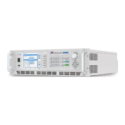
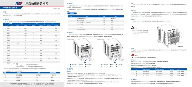
APM APM-SP-VDC-3U Series User manual

APM TECHNOLOGIES
PROFESSIONAL INNOVATIVE BRANDING SERVICE
High Power DC Power Supply
en.apmtech.cn
User Manual

01
Part NO. 18950-745-00
Contents
Contents
PROFESSIONAL INNOVATIVE BRANDING SERVICE
Preface ........................................................................................................................... 05
06Safety Notices .......................................................................................................................
071 About this Manual ...........................................................................................................
1.1 07Scope .........................................................................................................................................
1.2 07Targeted Audience .......................................................................................................
1.3 07Use of this Manual and Legal Notices .........................................................................
082 Unpacking .........................................................................................................................
2.1 08Scope of delivery .........................................................................................................
2.2 08Options ........................................................................................................................
2.3 09Checking for Shipping Damage ...................................................................................
2.4 Product Damage or Failure Repair 09..............................................................................
3 10Products Introduction .....................................................................................................
3.1 General Description 10.....................................................................................................
3.2 10Product Features .........................................................................................................
3.3 11Operation Instructions ..................................................................................................
3.4 11Operation Environments ...............................................................................................
3.5 11Product Storage ............................................................................................................
3.6 11Maintenance And Cleaning ...........................................................................................
3.7 Power Supply Voltage 11..................................................................................................
3.8 Fuse 12.............................................................................................................................
3.9 Warm-up Time 12.............................................................................................................
3.10 Unit Shutdown 12...........................................................................................................
3.11 Operation Precautions 12...............................................................................................
3.12 Start Procedure 13..........................................................................................................
4 Panel Description ............................................................................................................ 14
4.1 Front Panel Description ................................................................................................ 14
4.2 Rear Panel Description ................................................................................................ 7 1

03
02
PROFESSIONAL INNOVATIVE BRANDING SERVICE
Contents Contents
PROFESSIONAL INNOVATIVE BRANDING SERVICE
185 Menu Operation ................................................................................................................
5.1 Menu Structure 1............................................................................................................. 8
5.2 Main Screen ................................................................................................................... 21
5.3 Navigation Page........................................................................................................... 22
...................................................................................... 225.4 Operation Modes Introduction
5.5 Setting Menu ................................................................................................................ 23
5.5.1 Power/Sink Function.............................................................................................. 23
5.5.2 More Setting .......................................................................................................... 24
5.5.2.1 Vdc S/R ....................................................................................................... 24
5.5.2.2 Idc S/R ........................................................................................................ 25
5.5.2.3 Average ...................................................................................................... 25
5.5.2.4 CC/CV Prior ................................................................................................. 26
5.5.2.5 Hi-Variation .................................................................................................. 26
5.5.3 Load-2QO .............................................................................................................. 26
5.5.4 Sink On/Off ............................................................................................................ 26
5.5.5 Waveform ............................................................................................................. 27
5.5.6 Limitation .............................................................................................................. 27
5.5.6.1 Vlimit ........................................................................................................... 27
5.5.6.2 Ilimit ............................................................................................................. 28
5.5.6.3 Plimit ............................................................................................................ 28
5.5.6.4 Rlimit .......................................................................................................... 28
5.5.7 Protection .............................................................................................................. 29
5.5.7.1 OVP ............................................................................................................ 29
5.5.7.2 OCP ............................................................................................................ 29
5.5.7.3 OPP ............................................................................................................ 30
5.5.7.4 UVP ............................................................................................................. 30
5.5.7.5 Foldback ...................................................................................................... 30
5.5.8 Lock........................................................................................................................ 31
5.6 Parallel/Series ............................................................................................................... 31
5.7 Menu ............................................................................................................................. 31
5.7.1 Config ..................................................................................................................... 31
5.7.1.1 Remote Setup .............................................................................................. 32
5.7.1.1.1 RS232 Settings ............................................................................. 32
5.7.1.1.2 RS485 Settings ............................................................................ 33
5.7.1.1.3 USB/GPIB Setting ......................................................................... 33
5.7.1.1.4 LAN Setting ................................................................................. 34
5.7.1.1.5 CAN Setting ................................................................................. 34
5.7.1.2 System Setup ............................................................................................ 35
5.7.1.2.1 Buzzer .......................................................................................... 35
5.7.1.2.2 P/O Sta.......................................................................................... 35
5.7.1.2.3 P-Out ............................................................................................ 36
5.7.1.3 EXT Control ............................................................................................... 36
5.7.1.3.1 Setup ............................................................................................ 36
5.7.1.3.2 Monitor ......................................................................................... 37
5.7.1.4 System Info. .............................................................................................. 42
5.7.1.5 Run Info. ................................................................................................... 42
5.7.2 LCD Setup ........................................................................................................... 42
5.7.2.1 Display ....................................................................................................... 43
5.7.2.2 Date/Time .................................................................................................. 43
5.7.2.3 Color Test .................................................................................................. 43
5.7.3 Calibration ........................................................................................................... 43
5.7.4 Other ................................................................................................................... 44
5.7.4.1 Recall Def ................................................................................................. 44
5.7.4.2 Warning Log .............................................................................................. 44
5.7.4.3 Firmware Upd ........................................................................................... 45
5.8 Store/Recall ................................................................................................................. 45
5.9 Output Mode ................................................................................................................ 46
5.9.1 PLS Testing ......................................................................................................... 46
5.9.1.1 List mode ................................................................................................... 46
5.9.1.2 Program mode .......................................................................................... 49
5.9.1.3 Step mode ................................................................................................. 50
5.9.2 Special Func ....................................................................................................... 52
5.9.2.1 Test Mode .................................................................................................. 53
5.9.2.2 LV Mode .................................................................................................... 53
5.9.2.3 Short Mode ................................................................................................ 53
5.9.2.4 MCurr Share .............................................................................................. 54
5.9.2.5 Timer Func ................................................................................................ 54
5.9.2.6 Counting Func ........................................................................................... 55
5.10 Language ................................................................................................................... 56

80VDC
165VDC
250VDC
500VDC
750VDC
1000VDC
1500VDC
2250VDC
6000W
[1]
200A
-
-
32A
21A
-
-
-
12000W
[1]
400A
[1]
180A
-
64A
42A
32 A
21A
-
18000W
[1]
600A
-
[1]
180A
96A
63A
-
32A
21A
24000W
[1]
800A
[1]
360A
-
128A
84A
64A
42A
-
30000W
[1]
1000A
-
-
160A
105A
-
-
-
36000W
[1]
1200A
-
-
192A
126A
-
-
-
This series power supply in different power levels and either Advanced or Professional versions.
Please refer to the table below for the detailed difference between these configurations, optional
information as well.
Preface
Preface
Dear Customer,
Thank you for using this series High Power DC Power Supply, a product developed & manu-
factured by APM Technologies. We sincerely hope this product will meet your needs.
The sections outlined in this user manual are suitable for the following product models.
05
04
Contents
1
2
3
4
DDS arbitrary function generator
Solar panel I-V curve simulation function
Smart 3-stage charging algorithm simulation
Battery simulator function
Not supported
Supported
5Built-in Standard Automotive Power Network
Voltage Curves
6 Remote I/O control and monitor card
7 LAN & GPIB communication interface
NO. Description Advanced Version Professional Version
PROFESSIONAL INNOVATIVE BRANDING SERVICE PROFESSIONAL INNOVATIVE BRANDING SERVICE
Power
Voltage
3U Units 6U Units
Model guide
SP
Stands for Power
Stands for Voltage
For example: SP80VDC12000W
Note: SP stands for Switching Power.
Not supported
Not supported
Not supported
Not supported
Optional feature
Optional feature
Supported
Supported
Supported
Supported
Optional feature
Optional feature
8 Continuous source & sink function*Optional feature Optional feature
* This option must be specified at the time of order as they are installed at the factory prior to shipment.
[1] It is recommended that to decrease the output current to less than 90% of the rated current if the ambient
temperature exceeds 30℃.
Parallel/Series ...................................................................................................................6 57
6.1 Configuring All Slave Units .......................................................................................... 57
......................................................................................... 586.2 Configuring The Master Unit
6.3 .............................................................................. 60Parallel Mode Connection Diagram
6.4 ............................................................................... Series Mode Connection Diagram 61
627 Calibration .........................................................................................................................
7.1 Calibration Equipment required .................................................................................. 62
........................................................................................ 627.2 Calibration Equipment Setup
................................................................................................... 637.3 Calibration Procedure
7.3.1 Accessing Calibration Mode................................................................................... 63
7.3.2 Voltage Setting & Measurement Calibration........................................................... 64
5 7.3.3 Current Setting & Measurement Calibration........................................................... 6
7.3.4 Power Setting & Measurement Calibration 6............................................................. 6
67.3.5 Resistor Setting & Measurement Calibration.......................................................... 6
8 Installation 67 ........................................................................................................................
8.1 Product Dimensions .................................................................................................... 67
8.2 Installing Rack Mount Handles ..................................................................................... 67
8.3 Installation of An Optional Interface Card ..................................................................... 68
8.4 Shelf Mounting Diagram of The Unit ........................................................................... 69
70 8.5 Input Connection ..........................................................................................................
72 8.6 Connection to DC Loads ..............................................................................................
74 8.7 Remote Sensing ...........................................................................................................
9 Recycling and Disposal 75 .................................................................................................
10 Contact Us 75 .....................................................................................................................
Appendix A Specifications ................................................................................................ 76
Appendix B Warranty 100......................................................................................................
Appendix C Application Notes 102........................................................................................
Issue PA (2020-06)

About this Manual
07
1
1About this Manual
1-1
1.1 Scope
1.2 Targeted Audience
1.3 Use of this Manual and Legal Notices
This manual provides the reader with detailed product information as well as installation,
operation and maintenance instructions. This manual also provides our company contact
information so that you can tell us your suggestions and comments about the performance
of our products in order that we can continue to improve our product quality and our level of
service.
This manual is intended for product users and technical personnel that are involved with inst-
alling, operating and maintaining the product. Readers are required to have a certain degree
of electrical and mechanical knowledge and be familiar with basic electrical and mechanical
schematics.
All materials ( including but not limited to graphics, logos, symbols, data, etc.) in this manual
are owned by the APM Technologies. No part of this manual can be reproduced without prior
authorization from APM Technologies.
The content of this manual will continue to be updated and revised as inevitably there are slight
discrepancies or errors. Please check for updates at en.apmtech.cn and download the latest
version of this manual and information.
It is prohibited in any way to use all or part of the firmware or software developed by APM
Technologies for other commercial purposes. It is prohibited to decompile, decrypt or otherwise
damage the software developed by APM Technologies.
06
Safety Notices
Safety Notices
!
!
Warning!
Caution!
This symbol highlights operations that have the potential to endanger users, operation proce-
dures and instruction must be absolutely understood before use.
This symbol highlights precautions users need to take to avoid potential injury during equipment
operation.
This symbol highlights important instructions that need to be read before using the equipment.
This symbol indicates of high voltage risk aspects of the product or its use.
This symbol indicates parts that may be at a high temperature. Please do not touch this part
of the equipment to prevent scalding.
This symbol indicates that a grounded condition is required before operating the equipment;
the terminal with this label must be grounded to prevent electric shock.
Note
PROFESSIONAL INNOVATIVE BRANDING SERVICE PROFESSIONAL INNOVATIVE BRANDING SERVICE

Unpacking
09
2.4 Product Damage or Failure Repair
!
Caution!
2.3 Checking for Shipping Damage
All APM Technologies Company products have undergone stringent testing before delivery, but
inevitably damage can happen during transportation. Once you receive the product, please
immediately check if there is any packaging damage that may indicate damage to the product.
If you find damage related to product delivery, please immediately notify the transport company.
Make sure to take photos documenting the damage to the product, and send them to us so
that we can provide you with the best service.
In the unlikely event of product failure, please promptly contact APM Technologies or its dealer
and provide the serial number of the faulty DC power supply, detailed fault information and
pictures to help us identify the cause of the failure. If the power source requires repairing at the
factory or repair center, please pack it in the original packing material. Please assure to contact
APM to receive prior authorization for the product return and return instructions.
The handles on the front panel are for sliding in and out of the cabinet NOT for carrying.
08
Unpacking
1
2Unpacking
2.1 Scope of delivery
Item Included Quantity
Item
A
C
D
E
B
1
Power supply device
1 set
Screws to install Rack mount Handles
1
RS232 Serial Cable
USB Cable 1
2
Rack mount Handles (removable)
PROFESSIONAL INNOVATIVE BRANDING SERVICE PROFESSIONAL INNOVATIVE BRANDING SERVICE
The following accessories are included with each DC power supply. See table below for
reference.
2.2 Options
Item Included Quantity
Item
H
I
J
G
1
LAN & GPIB communication card
1
GPIB Cable
1
CAN communication card
Remote I/O control and monitor card 1
1
LAN Cable
K
L
1 set
Rack-mount slide kit and screws
Continuous source & sink function*As ordered
* This option must be specified at the time of order as they are installed at the factory prior to shipment.
Because of its weight, transport by hand should be avoided where possible. If unavoidable
then only the housing should be held and not on the exterior parts (handles, input/output
terminals or rotary knobs).
F
Quick Guide 1
M

Unpacking
09
2.4 Product Damage or Failure Repair
!
Caution!
2.3 Checking for Shipping Damage
All APM Technologies Company products have undergone stringent testing before delivery, but
inevitably damage can happen during transportation. Once you receive the product, please
immediately check if there is any packaging damage that may indicate damage to the product.
If you find damage related to product delivery, please immediately notify the transport company.
Make sure to take photos documenting the damage to the product, and send them to us so
that we can provide you with the best service.
In the unlikely event of product failure, please promptly contact APM Technologies or its dealer
and provide the serial number of the faulty DC power supply, detailed fault information and
pictures to help us identify the cause of the failure. If the power source requires repairing at the
factory or repair center, please pack it in the original packing material. Please assure to contact
APM to receive prior authorization for the product return and return instructions.
The handles on the front panel are for sliding in and out of the cabinet NOT for carrying.
08
Unpacking
1
2Unpacking
2.1 Scope of delivery
Item Included Quantity
Item
A
C
D
E
B
1
Power supply device
1 set
Screws to install Rack mount Handles
1
RS232 Serial Cable
USB Cable 1
2
Rack mount Handles (removable)
PROFESSIONAL INNOVATIVE BRANDING SERVICE PROFESSIONAL INNOVATIVE BRANDING SERVICE
The following accessories are included with each DC power supply. See table below for
reference.
2.2 Options
Item Included Quantity
Item
H
I
J
G
1
LAN & GPIB communication card
1
GPIB Cable
1
CAN communication card
Remote I/O control and monitor card 1
1
LAN Cable
K
L
1 set
Rack-mount slide kit and screws
Continuous source & sink function*As ordered
* This option must be specified at the time of order as they are installed at the factory prior to shipment.
Because of its weight, transport by hand should be avoided where possible. If unavoidable
then only the housing should be held and not on the exterior parts (handles, input/output
terminals or rotary knobs).
F
Quick Guide 1
M

11
Products Introduction
3.3 Operating Instructions
This product is a precision instrument, please read this manual carefully before use. In order
to ensure measurement accuracy it is recommended that a calibration check be performed on
this product every year.
3.4 Operating Environments
1. These power supplies must be used in a clean and dry laboratory or testing environment
with an ambient temperature of between 0°C and 40°C and the maximum relative humidity
is 95% at 35°C, 80% at 40°C.
2. Do not prolong the use of this power supply in a high temperature ambient.
3. Fans cool the power supply by drawing air through the front and exhausting it out the back.
Please assure that 20 cm space is present at the front and back of the unit for adequate air
circulation.
4. Do not operate this product in an environment that contains large amounts of dust, is subject
to strong shock and vibration, is in intense direct sunlight or contains corrosive gases.
3.5 Product Storage
Please store this product in an area with a temperature between -20 °C and 70 °C. If the
product is not in use for a long time, please keep it in the original carton or other similar
packaging and store it in a cool & dry place.
3.6 Maintenance and Cleaning
Before cleaning, you must disconnect the input power cord of this power supply. Using a brush
or sponge, gently wipe off any dust from the units exterior. To clean the products exterior use
only a small amount of non-aqueous cleaning solution such as isopropyl alcohol on a clean
cloth. Do not use a corrosive or abrasive cleaning solution to clean this product. The display
front panel can be cleaned with gauze damped in soft detergent. Cleaning of dust from the
interior of this product must be carried out with a low pressure air gun, and we prefer that such
a clean work be performed by an authorized dealer on behalf of the user.
1
3
This series of programmable power supply is high power density power supplies that can
provide stable output and accurate measurement parameter. 19'' enclosure design with
standard RS232/RS485/USB communication interfaces which is especially suitable for
automated test systems.
Large color touch screen with intuitive interface provides an excellent intuition operational ●
experience.
3-phase input voltage meets worldwide power distribution regulation, AC mains 180~240Vac/●
340~460Vac for optional.*
Constant voltage (CV), constant current (CC) and constant power (CP) operation mode, CC●
or CV working priority setting.
DDS arbitrary function generator.●
Solar panel I-V curve simulation function.●
Smart 3-stage charging algorithm simulation.●
Battery simulator function.●
Continuous source & sink function , with APM DC E-load to expand loading capability. ●*
List/Step mode programming.●
TTL/Analog control and monitoring.●
Built-in standard automotive power network voltage curves.●
Full protection: OVP, OCP, OPP and OTP protection.●
Supports master-slave mode, paralleling up to 16 units.●
Supports SCPI commands, provides web GUI function.●
10
Products Introduction
3.1 General Description
3.2 Product Features
PROFESSIONAL INNOVATIVE BRANDING SERVICE PROFESSIONAL INNOVATIVE BRANDING SERVICE
* This option must be specified at the time of order as they are installed at the factory prior to
shipment. Make sure that the AC input voltage is within the product's operating specification before plugging
in or connecting to the source, and that the power switch is in the OFF state.
3.7 Power Supply Voltage

13
12
!
Caution!
The protective safety earth/ground connection must connect first and disconnect after the
AC line and neutral wires. All approved AC power connectors are designed to meet this
requirement. If the input wires are directly connected to an AC mains circuit assure that
the AC source is deactivated prior to making or disconnecting the connection.
3.8 Fuse
The AC mains fuses installed inside the product are designed to protect the input from major
failures, and should not fail under normal operating conditions. Therefore, any sign of fuse
failure is an indication that other part(s) of the product is damaged. If fuse melting happens,
we recommend that the product be sent back to us for repair.
!
Warning!
No user serviceable components enclosed. Do not disassemble the power's enclosure/
case to replace the fuse, as there is a danger of sustaining an electric shock.
Products Introduction
3.9 Warm-up Time
Once the power supply is switched on, all features of the unit are operable after the start
routine has completed. However in order to achieve the specified operating accuracy, please
allow the power supply to operate for a warm-up time of 30 minutes.
Panel Description
PROFESSIONAL INNOVATIVE BRANDING SERVICE PROFESSIONAL INNOVATIVE BRANDING SERVICE
3.10 Unit Shutdown
When you no longer need to use this product, please make sure the front panel power switch
is set to the “OFF” state. After the AC power is switched off the internal fan will continue to run
for a few seconds to allow the internal capacitors to discharge. When discharging is completed,
the unit will automatically shut down.
3.11 Operation Precautions
1. When the unit is first turned on the DC output is in a deactivated state. It can be activated
by pressing the output turn on push button on the front panel or by remote control command.
2. Before turning on the DC power output, check that all the setting values of the power supply
are in accordance with the load requirements.
3.12 Start Procedure
The power source is turned ON using the power toggle switch located on the left hand side of
the front panel. A splash screen will appear as shown below.
After several seconds, the LCD will display the Diagnostics screen.
The diagnostics will take several seconds to complete. If all results are OK, the unit will revert
to the default main screen.
Please contact APM CS engineer for support if there is any failed item in this self-checking page.
DC Source
Self Checking
Model
Serial NO.
FPGA1 Ver.
FPGA2 Ver.
DSP Ver.
Display Ver.
Remote Ver.
Option Check
Protect Check
Control Check
EEPROM Check
SP80VDC6000W
0166481953000003
V100R100C11
V100R100C08
V100R001C13
V100R001C19
V100R001C06
Ext-I/O NA GPIB/LAN NA
FAN OK Temp OK
1. OK 2. OK 3. OK 4. OK
OK

15
14
3
Panel DescriptionPanel Description
Selection soft keys
PROFESSIONAL INNOVATIVE BRANDING SERVICE PROFESSIONAL INNOVATIVE BRANDING SERVICE
1
4Panel Description
4.1 Front Panel Description
2
1
Color touch screen
Power Switch
For 3U models, rotate power switch clockwise to turn on the unit. Rotate power switch count-
erclockwise to turn off the unit. The 6U product is fitted with a mains input circuit breaker on
the top left-hand side of the front panel. The power off position of the circuit breaker handle
is marked "O". The power on position of the circuit breaker is marked "I".
The color LCD touch screen displays all settings, measurements, menus and warning message.
It may also be used to enter parameter values and settings by using its touch screen function.
The user can use his fingertip or the built-in stylus inside the front panel directly to control the
unit.
There are six soft keys located along the right hand side of the LCD screen. The labels of these
key will change when selecting different screens. To select any of these soft keys, either press
the area on the touch LCD or press the actual button on the right hand side of the screen.
4
Voltage/Current & Power setting knob
Turning the shuttle to right (clockwise) increments a selected field value. Turning it to the left
(counter clockwise) decrements a selected field value. The setting value will be effective
immediately without pressing the [Enter] key.
The default location of the cursor after rotating knob is at the first digit after the decimal point.
All the yellow characters can be set. To enter parameter values using the LCD screen,
after touching the setting zone. An on-screen decimal keypad will pop up. Touch the relevant
number keys in screen to enter a value and press the [Enter] key when done. To abort, press
the [ESC] key instead and the previous value will appear.
1 2 3457 6

17
16
PROFESSIONAL INNOVATIVE BRANDING SERVICE PROFESSIONAL INNOVATIVE BRANDING SERVICE
Menu Keypad
Keys
Selects the function setting menu
Purpose Manual Reference
[Menu]
Selects value field or menu /Screen snapshot, importing
and firmware upgrade
Returns to the main screen
The second function key can be effective only when Shift key is pressed. And the Shift key will
be illuminated.
Menu
Cursor / IMAGE/FILE
Main
On/Off
Lock
Shift
RECALL
STORE
Enter
Toggles output on or off
Lock all the keys and rotary knob
Composite key, enables the second function indicated by
the word under/ on the function keys
Recalls the setup from internal memory
Stores the settings in non-volatile memory.
Up key
Down key
Confirm key
[Cursor]/[Shift]+[Cursor]
[Main]
[On/Off]
[Lock]
[Shift]
[Shift]+ [▲]
[Shift]+ [▼]
[◄]
[►]
[Enter]
6
USB Port
This USB port on the front panel is for data transfers and firmware upgrade.
7
Stylus
For accurately touching the touch screen display.
Panel DescriptionPanel Description
4.2 Rear Panel Description
1
LAN & GPIB communication interface (optional) .*
2
External TTL/Analog control interface.
3
System Bus, for master/slave system data transmission.
4
Termination resistor CAN-R.
5
Vs+/Vs- remote sense connections.
6
DC output negative/positive terminal.
7
AC mains input connector.
* These interface option installs in place of the standard RS485/RS232/USB interface,
occupies the same physical slot.
5
Numeric and functional keys
Decimal Keypad
Keys
Back to previous screen or entry
Purpose Manual Reference
[ESC]
[0]~[9]
[.] / ( [LOCAL] )
0 9
~
ESC
.
Allow direct entry of parameter values
/ ( LOCAL )
Decimal point key/Keypad unlock function key or press
this key to switch the control mode from remote control
back to the manual operating mode
If the front panel is locked (Lock is set to ON), the shuttle knob is disable.
Note
1 43 2 5 6 7
USB
RS 485
RS 232

19
18
Menu operation Menu operation
PROFESSIONAL INNOVATIVE BRANDING SERVICE PROFESSIONAL INNOVATIVE BRANDING SERVICE
1
5Menu Operation
5.1 Menu Structure
The table below shows the entire menu system at once. Each section will be covered in
subsequent sections in more detail.
There are three levels of nested menu under the Main Screen. The main screen is always the
first screen displayed after the power source is turned on. All sub screens can be accessed
using the front panel keys or touch screen.
Menu Description
Setting
Power/Sink
Power
Sink
Power+Sink
More Setting
Vdc S/R
Enable
Rise-V/ms
Fall-V/ms
Idc S/R
Enable
Rise-A/ms
Fall-A/ms
Average
SLOW
MID
FAST
CC/CV Prior
CC Prior
CV Prior
Delay Time
HI-Variation
ON
OFF
Enable power mode only
Enable sink mode only
Enable power and sink mode at the same time
Enable the slew setting
Voltage rise slew rate setting
Voltage fall slew rate setting
Enable the slew setting
Current rise slew rate setting
Current fall slew rate setting
Set average time at 200ms
Set average time at 50ms
Set average time at 10ms
Set CC mode in priority
Set CV mode in priority
Set the slew rate of voltage or current contrary to the
selected priority mode.
Enable the internal dummy load
Disable the internal dummy load
Load-2QO
Limitation
Vlimit
Vlimit-H/V
Vlimit-L/V
Ilimit
Plimit-H/W
Plimit-L/W
Rlimit
Rlimit-H/Ω
Rlimit-L/Ω
Protection
Enable
Enable
Delay/s
Set the maximum voltage
Set the minimum voltage
Set the maximum power
Set the minimum power
Set the maximum output programmable resistance
Set the minimum output programmable resistance
Enable over voltage protection
Enable over current protection
Set the delay time
Sink On/Off
Waveform
Ilimit-H/A
Ilimit-L/A
Set the maximum current
Set the minimum current
Plimit
OVP
Delay/s
Range/V
Set the delay time
Set the OVP value
OCP
Range/A Set the OCP value
Enable
Delay/s
Enable over power protection
Set the delay time
OPP
Range/W Set the OPP value
Enable
Delay/s
Enable the foldback protection
Set the delay time
Foldback
Range CV-CC or CC-CV, this function turns off the output when
the output mode is changed
Lock Lock the front panel keys and touch screen
Enable
Delay/s
Enable under voltage protection
Set the delay time
UVP
Range/V Set UVP value
This manual suits for next models
1
Table of contents
Other APM Power Supply manuals
Popular Power Supply manuals by other brands

Akyga
Akyga AK-PD-05 user manual

nextys
nextys NPSM40 Series instruction manual

Puls
Puls DIMENSION QS5-Series instruction manual

Pulsar
Pulsar AWO 205PU Assembly instructions

Emerson
Emerson Bristol ControlWave PAC Redundancy Product overview

Moser Systemelektrik
Moser Systemelektrik TerraMo instruction manual