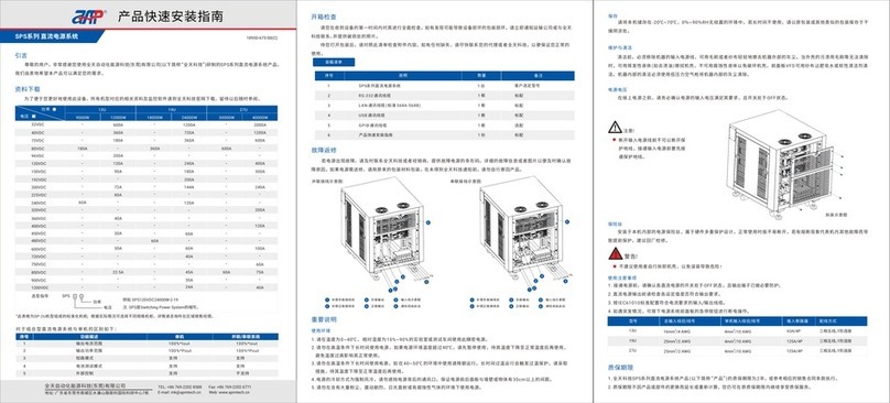
APM SP-300 Series User manual

APM TECHNOLOGIES
PROFESSIONAL INNOVATIVE BRANDING SERVICE
SP-300 Series
Single-phase Programmable AC Power Supply
en.apmtech.cn
User Manual

1
Contents
Contents
Preface ........................................................................................................................................... 4
Safety Notices ................................................................................................................................ 5
1 About this Manual ..................................................................................................................... 6
1.1 Scope .............................................................................................................................. 6
1.2 Targeted Audience ............................................................................................................... 6
1.3 Use of this Manual and Legal Notices ............................................................................... 6
2 Unpacking .................................................................................................................................... 7
2.1 Packing List ........................................................................................................................... 7
2.2 Checking for Shipping Damage .......................................................................................... 8
2.3 Failure Repair ....................................................................................................................... 8
3 Products Introduction ............................................................................................................... 8
3.1 Product Description ............................................................................................................ 8
3.2 Product Features ................................................................................................................. 9
3.3 Operation Instructions ...................................................................................................... 10
3.4 Operation Environments .................................................................................................... 10
3.5 Maintenance and Cleaning ................................................................................................ 10
3.6 Product Storage ............................................................................................................... 11
3.7 Power Supply Voltage ...................................................................................................... 11
3.8 Fuse ................................................................................................................................... 11
3.9 Warm-up Time ................................................................................................................... 11
3.10 Starting Procedure .......................................................................................................... 12
4 Panel Description ................................................................................................................... 13
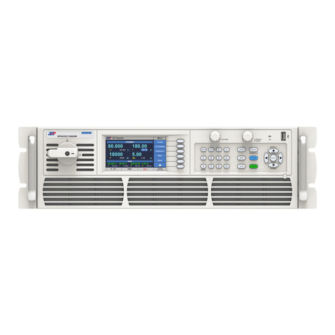
4.1 Front Panel Description .................................................................................................... 13
4.2 Rear Panel Description ..................................................................................................... 15
Part NO. 18950-677-00
PROFESSIONAL INNOVATIVE BRANDING SERVICE

2
PROFESSIONAL INNOVATIVE BRANDING SERVICE
3
Contents Contents
5 Menu Operation ....................................................................................................................... 18
5.1 Menu Introduction ............................................................................................................ 18
5.1.1 Menu Structure ............................................................................................................ 18
5.1.2 Introduction to Front Panel Operations .................................................................... 20
5.1.3 Key Operations and Touch Screen Operation ........................................................... 20
5.2 Menu Operation ................................................................................................................ 23
5.2.1 Setting Item ................................................................................................................ 23
5.2.1.1 Output & More Setting ........................................................................................ 23
5.2.1.2 Measurement Setting ......................................................................................... 28
5.2.1.3 Waveform Viewer Setting .................................................................................. 32
5.2.1.4 Limitation Setting ............................................................................................... 32
5.2.2 Menu Setting ............................................................................................................... 33
5.2.2.1 Config Setting ..................................................................................................... 33
5.2.2.2 LCD Setting ......................................................................................................... 41
5.2.2.3 Calibration ........................................................................................................... 43
5.2.2.4 Other Setting ....................................................................................................... 43
5.2.3 Output Mode .............................................................................................................. 44
5.2.3.1 PLD Testing ......................................................................................................... 44
5.2.3.2 Harmonics .......................................................................................................... 49
5.2.3.3 IEC Standard ........................................................................................................ 56
5.2.3.4 Special Func ........................................................................................................ 74
5.2.4 Parallel/Series/3-Phase ............................................................................................. 79
5.2.5 Store/Recall ................................................................................................................ 79
5.2.6 Lock ............................................................................................................................. 81
6 Master-slave Mode Operation ................................................................................................ 82
6.1 Setting the Units as Slave ................................................................................................. 82
6.2 Setting the Unit as Master ................................................................................................ 83
6.2.1 Parallel System ........................................................................................................... 82
6.2.2 Series System ............................................................................................................. 86
6.2.3 3-Phase System .......................................................................................................... 87
6.2.4 Error List of Master-slave Mode ................................................................................ 91
6.2.5 Function Instruction ................................................................................................... 91
7 Calibration ............................................................................................................................... 93
7.1 Calibration Equipment Required ...................................................................................... 93
7.2 Calibration Procedure ....................................................................................................... 93
7.2.1 Volt Setting & Measurement Calibration .................................................................. 94
7.2.2 Current Measurement Calibration ............................................................................. 95
7.2.2.1 I Range High, AC Low Current Coefficient ......................................................... 96
7.2.2.2 I Range High, AC High Current Coefficient ........................................................ 96
7.2.2.3 I Range High, DC Low Current Coefficient ......................................................... 97
7.2.2.4 I Range High, DC High Current Coefficient ....................................................... 97
7.2.3 Saving Calibration Coefficient ................................................................................... 98
8 Installation ................................................................................................................................ 99
8.1 Product Dimensions .......................................................................................................... 99
8.2 Installing Rack Mount Handles ...................................................................................... 100
8.3 Installing the Optional Interface Cards .......................................................................... 100
8.4 Shelf Mounting Diagram of AC Source ......................................................................... 102
8.5 Input Connection ............................................................................................................. 102
8.6 Output Connection .......................................................................................................... 104
8.7 Remote Compensation .................................................................................................. 105
9 Troubleshooting .................................................................................................................... 106
10 Recycling and Disposal ....................................................................................................... 108
11 Contact Us ........................................................................................................................... 108
Appendix A Specifications ....................................................................................................... 109
Appendix B Fixed Waveforms .................................................................................................. 113
Appendix C Warranty ................................................................................................................ 123
PROFESSIONAL INNOVATIVE BRANDING SERVICE

Preface
Dear Customer,
Thank you for using this SP-300 Series Single-phase Programmable AC Power Supply, a product
developed & manufactured by APM Technologies. We sincerely hope this product can meet
your needs.
The sections outlined in this user manual are suitable for the following product models:
150VAC
300VAC
600W 1000W 1500W 2000W
5.6A
2.8A
9.2A
4.6A
13.8A
6.9A
16A
8A
3000W
27.6A
13.8A
4000W
32A
16A
5000W
46A
23A
4U Units
Model guide SP
Power
Voltage
For example: SP300VAC2000W
Note: SP stands for Switching Power.
RU stands for Rack Unit 1 ¾” or 4.44 cm.
2U Units 3U Units
Advanced Version Professional Version
115~1000Hz 15~1200Hz
2IEC 61000-4-11
IEC 61000-4-11, IEC 61000-4-14,
IEC 61000-4-28, IEC 61000-4-13,
IEC 61000-3-2, IEC 61000-3-3
3
4
5Remote I/O & Parallel
Multiphase Link Card
6GPIB communication interface
Output impedance function
Harmonics/inter-harmonics
generation and measuring
function
SP-300 Series Programmable AC Power Supply are divided into Advanced Versions and Profe-
ssional Versions according to the expected needs of different power supply's application areas.
The following table lists the difference between the two versions and optional functions.
Voltage
Power
NO. Description
Output frequency range
IEC Standards met
Not supported
Not supported
Optional Feature
Optional Feature
Supported
Supported
Optional Feature
Optional Feature
4
Preface
Version G, updated February 2021
PROFESSIONAL INNOVATIVE BRANDING SERVICE
Safety Notices
!
!
Warning!
Caution!
This symbol highlights operations that have the potential to endanger users, operation proce-
dures and instructions must be completely understood before use.
Documentation must be consulted in all cases where this symbol is marked.
This symbol highlights important instructions that need to be read before using the equipment.
This symbol indicates of high voltage risk aspects of the product or its use.
This symbol indicates parts that may be at a high temperature. Please do not touch this part
of the equipment to prevent scalding.
This symbol indicates that a grounded condition is required before operating the equipment;
the terminal with this label must be grounded to prevent electric shock.
Note
5
Safety Notices
If the equipment is used in a manner not specified by the manufacturer, the protection provided
by the equipment may be impaired.
PROFESSIONAL INNOVATIVE BRANDING SERVICE

Preface
Dear Customer,
Thank you for using this SP-300 Series Single-phase Programmable AC Power Supply, a product
developed & manufactured by APM Technologies. We sincerely hope this product can meet
your needs.
The sections outlined in this user manual are suitable for the following product models:
150VAC
300VAC
600W 1000W 1500W 2000W
5.6A
2.8A
9.2A
4.6A
13.8A
6.9A
16A
8A
3000W
27.6A
13.8A
4000W
32A
16A
5000W
46A
23A
4U Units
Model guide SP
Power
Voltage
For example: SP300VAC2000W
Note: SP stands for Switching Power.
RU stands for Rack Unit 1 ¾” or 4.44 cm.
2U Units 3U Units
Advanced Version Professional Version
115~1000Hz 15~1200Hz
2IEC 61000-4-11
IEC 61000-4-11, IEC 61000-4-14,
IEC 61000-4-28, IEC 61000-4-13,
IEC 61000-3-2, IEC 61000-3-3
3
4
5Remote I/O & Parallel
Multiphase Link Card
6GPIB communication interface
Output impedance function
Harmonics/inter-harmonics
generation and measuring
function
SP-300 Series Programmable AC Power Supply are divided into Advanced Versions and Profe-
ssional Versions according to the expected needs of different power supply's application areas.
The following table lists the difference between the two versions and optional functions.
Voltage
Power
NO. Description
Output frequency range
IEC Standards met
Not supported
Not supported
Optional Feature
Optional Feature
Supported
Supported
Optional Feature
Optional Feature
4
Preface
Version G, updated February 2021
PROFESSIONAL INNOVATIVE BRANDING SERVICE
Safety Notices
!
!
Warning!
Caution!
This symbol highlights operations that have the potential to endanger users, operation proce-
dures and instructions must be completely understood before use.
Documentation must be consulted in all cases where this symbol is marked.
This symbol highlights important instructions that need to be read before using the equipment.
This symbol indicates of high voltage risk aspects of the product or its use.
This symbol indicates parts that may be at a high temperature. Please do not touch this part
of the equipment to prevent scalding.
This symbol indicates that a grounded condition is required before operating the equipment;
the terminal with this label must be grounded to prevent electric shock.
Note
5
Safety Notices
If the equipment is used in a manner not specified by the manufacturer, the protection provided
by the equipment may be impaired.
PROFESSIONAL INNOVATIVE BRANDING SERVICE
1About this Manual
1-1
1.1 Scope
1.2 Targeted Audience
1.3 Use of this Manual and Legal Notices
This manual provides the reader with detailed product information as well as installation,
operation and maintenance instructions. This manual also provides our company contact
information so that you can tell us your suggestions and comments about the performance
of our products in order that we can continue to improve our product quality and our level of
service.
This manual is intended for product users and technical personnel that are involved with inst-
alling, operating and maintaining the product. Readers are required to have a certain degree
of electrical and mechanical knowledge and be familiar with basic electrical and mechanical
schematics.
All materials ( including but not limited to graphics, logos, symbols, data, etc.) in this manual
are owned by the APM Technologies. No part of this manual can be reproduced without prior
authorization from APM Technologies.
The content of this manual will continue to be updated and revised as inevitably there are slight
discrepancies or errors. Please check for updates at en.apmtech.cn and download the latest
version of this manual and information.
It is prohibited in any way to use all or part of the firmware or software developed by APM
Technologies for other commercial purposes. It is prohibited to decompile, decrypt or otherwise
damage the software developed by APM Technologies.
6
About this Manual
PROFESSIONAL INNOVATIVE BRANDING SERVICE
2.1 Packing List
Unpacking
1
2
SP-300 Series Programmable AC Power Supply
Rack Mount Brackets
Output Terminal Cover Box
Input Terminal Cover Box
Screws
RS-232 Communication Cable
LAN communication Cable (568A-568B)
Power Cord
USB Communication Cable
GPIB Communication Cable
System Bus Communication Cable (DVI)
BNC Cable
Quick Guide
As ordered
Standard
Standard
Standard
Fasten item B
Standard
Standard
Standard
Standard
Optional
Optional
Optional
English Version
Descriptions
Item
A
B
C
D
E
F
G
H
I
J
K
L
[1] The LAN communication cable is optional for 2U units.
2U model is standard with three-pin plug power cable (16A). 3U/4U model is standard with power cable(1.5M). [2]
Quantity Remarks
1
2
1
1
12
1
1
1
1
1
1
1
1
M
7
Unpacking
[1]
[2]
PROFESSIONAL INNOVATIVE BRANDING SERVICE
A
GIJ
EA
K L
B C D F
H M

1About this Manual
1-1
1.1 Scope
1.2 Targeted Audience
1.3 Use of this Manual and Legal Notices
This manual provides the reader with detailed product information as well as installation,
operation and maintenance instructions. This manual also provides our company contact
information so that you can tell us your suggestions and comments about the performance
of our products in order that we can continue to improve our product quality and our level of
service.
This manual is intended for product users and technical personnel that are involved with inst-
alling, operating and maintaining the product. Readers are required to have a certain degree
of electrical and mechanical knowledge and be familiar with basic electrical and mechanical
schematics.
All materials ( including but not limited to graphics, logos, symbols, data, etc.) in this manual
are owned by the APM Technologies. No part of this manual can be reproduced without prior
authorization from APM Technologies.
The content of this manual will continue to be updated and revised as inevitably there are slight
discrepancies or errors. Please check for updates at en.apmtech.cn and download the latest
version of this manual and information.
It is prohibited in any way to use all or part of the firmware or software developed by APM
Technologies for other commercial purposes. It is prohibited to decompile, decrypt or otherwise
damage the software developed by APM Technologies.
6
About this Manual
PROFESSIONAL INNOVATIVE BRANDING SERVICE
2.1 Packing List
Unpacking
1
2
SP-300 Series Programmable AC Power Supply
Rack Mount Brackets
Output Terminal Cover Box
Input Terminal Cover Box
Screws
RS-232 Communication Cable
LAN communication Cable (568A-568B)
Power Cord
USB Communication Cable
GPIB Communication Cable
System Bus Communication Cable (DVI)
BNC Cable
Quick Guide
As ordered
Standard
Standard
Standard
Fasten item B
Standard
Standard
Standard
Standard
Optional
Optional
Optional
English Version
Descriptions
Item
A
B
C
D
E
F
G
H
I
J
K
L
[1] The LAN communication cable is optional for 2U units.
2U model is standard with three-pin plug power cable (16A). 3U/4U model is standard with power cable(1.5M). [2]
Quantity Remarks
1
2
1
1
12
1
1
1
1
1
1
1
1
M
7
Unpacking
[1]
[2]
PROFESSIONAL INNOVATIVE BRANDING SERVICE
A
GIJ
EA
K L
B C D F
H M

8
2.3 Product Damage or Failure Repair
2.2 Checking for Shipping Damage
All APM Technologies Company products have undergone stringent testing before delivery, but
inevitably damage can happen during transportation. Once you receive the product, please
immediately check if there is any packaging damage that may indicate damage to the product.
If you find damage related to product delivery, please immediately notify the transport company.
Make sure to take photos documenting the damage to the product, and send them to us so
that we can provide you with the best service.
In the unlikely event of product failure, please promptly contact APM Technologies or its dealer
and provide the serial number of the faulty AC power source, detailed fault information and
pictures to help us identify the cause of the failure. If the power source requires repairing at the
factory or repair center, please pack it in the original packing material. Please assure to contact
APM to receive prior authorization for the product return and return instructions.
Unpacking
This series of products are single phase programmable AC power sources, incorporate high
frequency PWM techniques, high speed DSP+CPLD control to provide low-distortion sine wave
output or other wave-shapes as needed. A isolated active input Power Factor Correction (PFC)
input power processing stage is used to efficiently provide a low THD high power factor input
characteristic.
3.1 Product Description
Products Introduction
1
3
!
Caution!
The handles on the front panel are for sliding in and out of the cabinet NOT for carrying.
Because of its weight, transport by hand should be avoided where possible. If unavoidable
then only the housing should be held and not on the exterior parts (handles, input/output
terminals or rotary knobs).
PROFESSIONAL INNOVATIVE BRANDING SERVICE
3.2 Products Features
Output voltage and frequency slope setting capability.
Turn ON / Turn OFF phase angle setting capability.
Transient mode function.
A large color easy to operate touch screen display that possess a complete set of functions.
Support for USB data import/export and screen snapshot from its' front panel.
AC and DC mixed or independent output modes for voltage DC offset simulation.
Maximum output voltage and current limit restriction setting capability. Support for constant
current output mode.
Sweep Function.
LIST / PULSE / STEP modes, which are suitable for simulation of power line disturbance
tests.
Phase Angle Dimmer simulation function.
Reverse current protection.
Built-in output metering capable of measuring 15 electrical parameters including output
voltage, current, frequency, etc.
Suitable for IEC 61000-3-2 and IEC 61000-3-2 tests.
The product includes comprehensive measurement functions and remote control and comm-
unications. The units feature standard 19'' (48.3 cm) rack or bench-top mounting, many system
based functions, local touch screen display and selector soft keys / knobs, remote analog and
digital input control of its' operation. It is designed to meet the needs of a wide range of app-
lications.
9
Products Introduction
PROFESSIONAL INNOVATIVE BRANDING SERVICE
IEC 61000-4-11 / IEC 61000-4-14 / IEC 61000-4-28 / IEC 61000-4-13 standard test requir-
ement waveforms are built-in.
Support for up to 2 units connected in series, 4 units connected in parallel and 3 units co-
mbined to provide a 3-phase output. Presently, 2U units can not support multi-unit mode.

8
2.3 Product Damage or Failure Repair
2.2 Checking for Shipping Damage
All APM Technologies Company products have undergone stringent testing before delivery, but
inevitably damage can happen during transportation. Once you receive the product, please
immediately check if there is any packaging damage that may indicate damage to the product.
If you find damage related to product delivery, please immediately notify the transport company.
Make sure to take photos documenting the damage to the product, and send them to us so
that we can provide you with the best service.
In the unlikely event of product failure, please promptly contact APM Technologies or its dealer
and provide the serial number of the faulty AC power source, detailed fault information and
pictures to help us identify the cause of the failure. If the power source requires repairing at the
factory or repair center, please pack it in the original packing material. Please assure to contact
APM to receive prior authorization for the product return and return instructions.
Unpacking
This series of products are single phase programmable AC power sources, incorporate high
frequency PWM techniques, high speed DSP+CPLD control to provide low-distortion sine wave
output or other wave-shapes as needed. A isolated active input Power Factor Correction (PFC)
input power processing stage is used to efficiently provide a low THD high power factor input
characteristic.
3.1 Product Description
Products Introduction
1
3
!
Caution!
The handles on the front panel are for sliding in and out of the cabinet NOT for carrying.
Because of its weight, transport by hand should be avoided where possible. If unavoidable
then only the housing should be held and not on the exterior parts (handles, input/output
terminals or rotary knobs).
PROFESSIONAL INNOVATIVE BRANDING SERVICE
3.2 Products Features
Output voltage and frequency slope setting capability.
Turn ON / Turn OFF phase angle setting capability.
Transient mode function.
A large color easy to operate touch screen display that possess a complete set of functions.
Support for USB data import/export and screen snapshot from its' front panel.
AC and DC mixed or independent output modes for voltage DC offset simulation.
Maximum output voltage and current limit restriction setting capability. Support for constant
current output mode.
Sweep Function.
LIST / PULSE / STEP modes, which are suitable for simulation of power line disturbance
tests.
Phase Angle Dimmer simulation function.
Reverse current protection.
Built-in output metering capable of measuring 15 electrical parameters including output
voltage, current, frequency, etc.
Suitable for IEC 61000-3-2 and IEC 61000-3-2 tests.
The product includes comprehensive measurement functions and remote control and comm-
unications. The units feature standard 19'' (48.3 cm) rack or bench-top mounting, many system
based functions, local touch screen display and selector soft keys / knobs, remote analog and
digital input control of its' operation. It is designed to meet the needs of a wide range of app-
lications.
9
Products Introduction
PROFESSIONAL INNOVATIVE BRANDING SERVICE
IEC 61000-4-11 / IEC 61000-4-14 / IEC 61000-4-28 / IEC 61000-4-13 standard test requir-
ement waveforms are built-in.
Support for up to 2 units connected in series, 4 units connected in parallel and 3 units co-
mbined to provide a 3-phase output. Presently, 2U units can not support multi-unit mode.

3.3 Operating Instructions
This product is a precision instrument, please read this manual carefully before using. In order
to ensure measurement accuracy it is recommended that this unit is calibrated annually by a
calibration laboratory.
To ensure the user safety, the input power cable, connector and accessories of this product
should be inspected at least annually.
3.4 Operating Environments
1. These power sources must be used in a clean and dry laboratory or testing environment
with an ambient temperature of between 0°C and 40°C and a relative humidity of between
5% and 95%.
2. Do not use this power source in a high temperature ambient for a prolonged period. Please
cease to use this product if its' case temperature of exceeds 45 degrees Celsius. Long term
operation of this product at a high ambient temperature may cause OTP (over temperature
protection) action.
3. For adequate air circulation please assure that 30 cm of space is present at the front and
back of the unit. Internal fans cool the power source by drawing air through the front and
exhausting it out the back.
4. Do not operate this product in an environment that contains large amounts of dust or corrosive
gases. Please do not subject the unit to strong shock and vibration or expose it to intense
direct sunlight.
3.5 Maintenance and Cleaning
Before cleaning, you must disconnect the input power cord of this power source. Gently wipe
off any dust from the units exterior using a brush or sponge or one can use only a small amount
of non-aqueous cleaning solution such as isopropyl alcohol on a clean cloth. Do not use a
corrosive or abrasive cleaning solution to clean this product. The display front panel can be
cleaned with cloth dampened in soft detergent. Cleaning of dust from the interior of this product
must be carried out with a low pressure air gun, and to prevent damage to internal components
we suggest that such cleaning be performed by an authorized dealer on behalf of the user.
10
Products Introduction
PROFESSIONAL INNOVATIVE BRANDING SERVICE
3.6 Product Storage
Please store this product in an area with a temperature between -40 °C and 85 °C and with a
relative humidity of between 5% and 95% non-condensing. If the product is not going to be
used for a long period, please keep it in the original carton or other similar packaging and store
it in a cool & dry place.
3.7 Power Supply Voltage
Make sure that the front panel power switch is in the OFF state and the AC input mains voltage
is within the product's operating specification before plugging in or connecting to the AC mains.
!
Caution!
The protective safety earth/ground connection must be connected first and disconnected
after the AC mains line and neutral wires. All approved AC power connectors are designed
to meet this requirement. If the input wires are directly connected to an AC mains circuit
assure that the AC source is deactivated prior to making or disconnecting the connection.
3.8 Fuse
The input AC fuses installed inside the product are designed to protect the units' input from
major component failures, and they should not fail under normal operating conditions. Accor-
dingly, any fuse failure is an indication that other parts of the product are damaged. If the input
fuses open circuit we recommend that the product be sent back to us for repair.
!
Warning!
Danger of electric shock. No user serviceable components enclosed. Do not disassemble
the power's enclosure / case to replace the fuse.
3.9 Warm-up Time
Once the power source is switched on the unit will enter a start-up routine that when completed
which will verify proper unit operation. All features of the unit are operable after this routine has
been successfully completed. In order to achieve the specified operating accuracy, it is reco-
mmended to allow the power supply to warm-up for a period of 30 minutes before use.
11
Products Introduction
PROFESSIONAL INNOVATIVE BRANDING SERVICE

3.3 Operating Instructions
This product is a precision instrument, please read this manual carefully before using. In order
to ensure measurement accuracy it is recommended that this unit is calibrated annually by a
calibration laboratory.
To ensure the user safety, the input power cable, connector and accessories of this product
should be inspected at least annually.
3.4 Operating Environments
1. These power sources must be used in a clean and dry laboratory or testing environment
with an ambient temperature of between 0°C and 40°C and a relative humidity of between
5% and 95%.
2. Do not use this power source in a high temperature ambient for a prolonged period. Please
cease to use this product if its' case temperature of exceeds 45 degrees Celsius. Long term
operation of this product at a high ambient temperature may cause OTP (over temperature
protection) action.
3. For adequate air circulation please assure that 30 cm of space is present at the front and
back of the unit. Internal fans cool the power source by drawing air through the front and
exhausting it out the back.
4. Do not operate this product in an environment that contains large amounts of dust or corrosive
gases. Please do not subject the unit to strong shock and vibration or expose it to intense
direct sunlight.
3.5 Maintenance and Cleaning
Before cleaning, you must disconnect the input power cord of this power source. Gently wipe
off any dust from the units exterior using a brush or sponge or one can use only a small amount
of non-aqueous cleaning solution such as isopropyl alcohol on a clean cloth. Do not use a
corrosive or abrasive cleaning solution to clean this product. The display front panel can be
cleaned with cloth dampened in soft detergent. Cleaning of dust from the interior of this product
must be carried out with a low pressure air gun, and to prevent damage to internal components
we suggest that such cleaning be performed by an authorized dealer on behalf of the user.
10
Products Introduction
PROFESSIONAL INNOVATIVE BRANDING SERVICE
3.6 Product Storage
Please store this product in an area with a temperature between -40 °C and 85 °C and with a
relative humidity of between 5% and 95% non-condensing. If the product is not going to be
used for a long period, please keep it in the original carton or other similar packaging and store
it in a cool & dry place.
3.7 Power Supply Voltage
Make sure that the front panel power switch is in the OFF state and the AC input mains voltage
is within the product's operating specification before plugging in or connecting to the AC mains.
!
Caution!
The protective safety earth/ground connection must be connected first and disconnected
after the AC mains line and neutral wires. All approved AC power connectors are designed
to meet this requirement. If the input wires are directly connected to an AC mains circuit
assure that the AC source is deactivated prior to making or disconnecting the connection.
3.8 Fuse
The input AC fuses installed inside the product are designed to protect the units' input from
major component failures, and they should not fail under normal operating conditions. Accor-
dingly, any fuse failure is an indication that other parts of the product are damaged. If the input
fuses open circuit we recommend that the product be sent back to us for repair.
!
Warning!
Danger of electric shock. No user serviceable components enclosed. Do not disassemble
the power's enclosure / case to replace the fuse.
3.9 Warm-up Time
Once the power source is switched on the unit will enter a start-up routine that when completed
which will verify proper unit operation. All features of the unit are operable after this routine has
been successfully completed. In order to achieve the specified operating accuracy, it is reco-
mmended to allow the power supply to warm-up for a period of 30 minutes before use.
11
Products Introduction
PROFESSIONAL INNOVATIVE BRANDING SERVICE

Programmable AC Source
Professional
SELF CHECKING
Model
Serial NO.
Control Version
Display Version
Remote Version
Loading System Parameters...
Self Testing
DRAM Check
Extern EEPROM Check
Extern RAM Check
Parallel Board Check
GPIB Check
PFC Check
Output Check
SP300VAC5000W
0134581738000004
V100R003C38
V100R003C28
V100R002C18
OK
OK
OK
OK
OK
100%
OK
OK
OK
OK
NA
OK
OK
3.10 Starting Procedure
Plug in the AC power and turn on the power switch on the front panel, the programmable AC
power source will execute a self-checking routine:
The company name APM Technologies will appear on the front panel display:
After 3 seconds, it will enter the self-testing mode;
DRAM Check, checks DRAM, if failed, shows as FAIL;
Extern EEPROM Check, checks the external EEPROM memory, if failed, shows as FAIL;
Extern RAM Check, checks the external RAM memory, if failed, shows as FAIL;
Parallel Board Check, checks whether remote I/O and parallel link board is installed and co-
nnected, if not, shows as NA.
GPIB Check, checks whether the GPIB communication board is being connected, if not, shows
as NA.
PFC Check, checks the units PFC board operation, if not operating correctly it shows as FAIL.
Output Check, checks the units output of 150V both 300V ranges, if the output voltage is not
within 100V± 8V and 200V±8V it shows as FAIL.
Note: If the PFC Check or Output Check shows a FAIL result, the power source will not operate.
If there is a FAIL result in any of the other tests, the power source is still operational. In this
case, press the [Enter] key to proceed to the MAIN screen.
12
Products Introduction
PROFESSIONAL INNOVATIVE BRANDING SERVICE
4.1 Front Panel Description
Panel Description
1
4
13
Panel Description
Front Panel of 2U Models
Front Panel of 3U Models
Front Panel of 4U Models
1 2 4 5 6 9 83 7
1 2 3 4 5 6 7 8 9
PROFESSIONAL INNOVATIVE BRANDING SERVICE

Programmable AC Source
Professional
SELF CHECKING
Model
Serial NO.
Control Version
Display Version
Remote Version
Loading System Parameters...
Self Testing
DRAM Check
Extern EEPROM Check
Extern RAM Check
Parallel Board Check
GPIB Check
PFC Check
Output Check
SP300VAC5000W
0134581738000004
V100R003C38
V100R003C28
V100R002C18
OK
OK
OK
OK
OK
100%
OK
OK
OK
OK
NA
OK
OK
3.10 Starting Procedure
Plug in the AC power and turn on the power switch on the front panel, the programmable AC
power source will execute a self-checking routine:
The company name APM Technologies will appear on the front panel display:
After 3 seconds, it will enter the self-testing mode;
DRAM Check, checks DRAM, if failed, shows as FAIL;
Extern EEPROM Check, checks the external EEPROM memory, if failed, shows as FAIL;
Extern RAM Check, checks the external RAM memory, if failed, shows as FAIL;
Parallel Board Check, checks whether remote I/O and parallel link board is installed and co-
nnected, if not, shows as NA.
GPIB Check, checks whether the GPIB communication board is being connected, if not, shows
as NA.
PFC Check, checks the units PFC board operation, if not operating correctly it shows as FAIL.
Output Check, checks the units output of 150V both 300V ranges, if the output voltage is not
within 100V± 8V and 200V±8V it shows as FAIL.
Note: If the PFC Check or Output Check shows a FAIL result, the power source will not operate.
If there is a FAIL result in any of the other tests, the power source is still operational. In this
case, press the [Enter] key to proceed to the MAIN screen.
12
Products Introduction
PROFESSIONAL INNOVATIVE BRANDING SERVICE
4.1 Front Panel Description
Panel Description
1
4
13
Panel Description
Front Panel of 2U Models
Front Panel of 3U Models
Front Panel of 4U Models
1 2 4 5 6 9 83 7
1 2 3 4 5 6 7 8 9
PROFESSIONAL INNOVATIVE BRANDING SERVICE

.
ESC
.
09
~
0
+/- ( Shift + )
LOCAL ( )
IMAGE/FILE ( Shift + )
PHASE ( Shift + )
Menu
Cursor
Main
On/Off
Shift
Lock
Cursor
Lock
Functional keys and multifunctional keys
6
[0]~[9]
[.]
[ESC]
[Shift]+[0]
Local([.])
[Menu]
[Cursor]
[Main]
[On/Off]
[Lock]
[Shift]
[Shift]+[Cursor]
[Shift]+[Lock]
To select front panel operation / keypad unlock
function key, used to unlock the panel buttons.
Keys Name and the function Manual Reference
To enter function setting items.
Press to return to the Main screen.
To turn the output of AC source On or Off.
Press to lock the front panel keys.
This shift key is used to select the alternate
operation of a key, indicated by the word under
the key.
Screen snapshot/importing/firmware upgrade.
1-phase mode or 3-phase mode.(unavailable)
Numeric keys.
Decimal point key.
Esc key.
To set the direction of DC offset.
Cursor to highlight desired selection.
14
Panel Description
1
Input power switch.
USB port is for data transfers and upgrading software.
Color touch screen.
Operation selection soft keys, to select displayed menu functions.
Numeric and functional keys.
2
3
4
5
PROFESSIONAL INNOVATIVE BRANDING SERVICE
15
Panel Description
8
Rotary knob, used to navigate menu items or for incrementing/decrementing values one step at a
time or to move cursor position.
Stylus (Touch pen) for accurately touching the touch screen display.
9
7
Confirm key and multifunctional keys.
RECALL ( Shift + )
STORE ( Shift + )
Enter
[Shift]+[ ]
[Shift]+[ ]
[ ]
[ ]
[Enter]
Keys Name and the function Manual Reference
Recall the setup from internal memory.
Store the settings in non-volatile memory.
Up/Left key.
Down/Right key.
Confirm key.
4.2 Rear Panel Description
1
AC/DC output terminals.
Voltage sensor terminals.
Remote I/O card (Optional).
2
3
Interface Description
SYNC
TTL/ANALOG TTL signal/analog input interface.
BNC connector input by external analog signal to control waveform amplitude.
Rear Panel of 2U Models
PROFESSIONAL INNOVATIVE BRANDING SERVICE
21 4
356

.
ESC
.
09
~
0
+/- ( Shift + )
LOCAL ( )
IMAGE/FILE ( Shift + )
PHASE ( Shift + )
Menu
Cursor
Main
On/Off
Shift
Lock
Cursor
Lock
Functional keys and multifunctional keys
6
[0]~[9]
[.]
[ESC]
[Shift]+[0]
Local([.])
[Menu]
[Cursor]
[Main]
[On/Off]
[Lock]
[Shift]
[Shift]+[Cursor]
[Shift]+[Lock]
To select front panel operation / keypad unlock
function key, used to unlock the panel buttons.
Keys Name and the function Manual Reference
To enter function setting items.
Press to return to the Main screen.
To turn the output of AC source On or Off.
Press to lock the front panel keys.
This shift key is used to select the alternate
operation of a key, indicated by the word under
the key.
Screen snapshot/importing/firmware upgrade.
1-phase mode or 3-phase mode.(unavailable)
Numeric keys.
Decimal point key.
Esc key.
To set the direction of DC offset.
Cursor to highlight desired selection.
14
Panel Description
1
Input power switch.
USB port is for data transfers and upgrading software.
Color touch screen.
Operation selection soft keys, to select displayed menu functions.
Numeric and functional keys.
2
3
4
5
PROFESSIONAL INNOVATIVE BRANDING SERVICE
15
Panel Description
8
Rotary knob, used to navigate menu items or for incrementing/decrementing values one step at a
time or to move cursor position.
Stylus (Touch pen) for accurately touching the touch screen display.
9
7
Confirm key and multifunctional keys.
RECALL ( Shift + )
STORE ( Shift + )
Enter
[Shift]+[ ]
[Shift]+[ ]
[ ]
[ ]
[Enter]
Keys Name and the function Manual Reference
Recall the setup from internal memory.
Store the settings in non-volatile memory.
Up/Left key.
Down/Right key.
Confirm key.
4.2 Rear Panel Description
1
AC/DC output terminals.
Voltage sensor terminals.
Remote I/O card (Optional).
2
3
Interface Description
SYNC
TTL/ANALOG TTL signal/analog input interface.
BNC connector input by external analog signal to control waveform amplitude.
Rear Panel of 2U Models
PROFESSIONAL INNOVATIVE BRANDING SERVICE
21 4
356

6
5
4
Cooling air outlet.
Standard communication interfaces, RS-485, RS-232 and USB. LAN and GPIB is optional.
Input terminals.
Panel Description
16
External Control Instruction
Pin 1
Pin 2
Pin 3
Pin 4
Pin 5
Pin 6
Pin 7
Pin 8~10
OUT OFF = Low (0~0.5V); OUT ON = High (4.5~5.5V)
KEEP OFF Disable = Low (0~0.5V); KEEP OFF Enable = High (4.5~5.5V)
RESET Active = Low (0~0.5V); RESET NOT Active = High (4.5~5.5V)
0 = Low (0~0.5V); 1 = High (4.5~5.5V)
Not Used
GND
ON/OFF
[1]
KEEP OFF
RESET
CALL 1
CALL 2
CALL 3
N/A
EXT. V
Pin 1~2 These two pins will connected internally when the unit passed the
test mode.
RELAY1-PASS
TTL
Pin 7~8
Pin 9~10
Pin 3~4
Pin 5~6
RELAY4
RELAY3-RUN
RELAY2-FAIL These two pins will connected internally when the unit failed the
test mode.
These two pins will connected internally when the unit is running.
Not Used
GND
[1] If the KEEP OFF signal keeps high (enable) there will be always no output.
PROFESSIONAL INNOVATIVE BRANDING SERVICE
7
6
5
1
AC/DC output terminals.
Voltage sensor terminals.
Cooling air outlets.
Remote I/O & Parallel Multiphase Link card (Optional).
2
3
4
Standard communication interfaces, RS-485, RS-232, USB and LAN.
GPIB communication interface, optional.
Input terminals.
Interface Description
SYNC
CAN-R
SYSTEM BUS
TTL/ANALOG
Used for communication between master and slaves.
TTL signal/analog input interface. (Refer to P18 for details.)
Connect CAN-R in parallel mode.
BNC connector input by external analog signal to control waveform amplitude.
Rear Panel of 3U Models
Rear Panel of 4U Models
Panel Description
17
PROFESSIONAL INNOVATIVE BRANDING SERVICE
2 3 4567
1

6
5
4
Cooling air outlet.
Standard communication interfaces, RS-485, RS-232 and USB. LAN and GPIB is optional.
Input terminals.
Panel Description
16
External Control Instruction
Pin 1
Pin 2
Pin 3
Pin 4
Pin 5
Pin 6
Pin 7
Pin 8~10
OUT OFF = Low (0~0.5V); OUT ON = High (4.5~5.5V)
KEEP OFF Disable = Low (0~0.5V); KEEP OFF Enable = High (4.5~5.5V)
RESET Active = Low (0~0.5V); RESET NOT Active = High (4.5~5.5V)
0 = Low (0~0.5V); 1 = High (4.5~5.5V)
Not Used
GND
ON/OFF
[1]
KEEP OFF
RESET
CALL 1
CALL 2
CALL 3
N/A
EXT. V
Pin 1~2 These two pins will connected internally when the unit passed the
test mode.
RELAY1-PASS
TTL
Pin 7~8
Pin 9~10
Pin 3~4
Pin 5~6
RELAY4
RELAY3-RUN
RELAY2-FAIL These two pins will connected internally when the unit failed the
test mode.
These two pins will connected internally when the unit is running.
Not Used
GND
[1] If the KEEP OFF signal keeps high (enable) there will be always no output.
PROFESSIONAL INNOVATIVE BRANDING SERVICE
7
6
5
1
AC/DC output terminals.
Voltage sensor terminals.
Cooling air outlets.
Remote I/O & Parallel Multiphase Link card (Optional).
2
3
4
Standard communication interfaces, RS-485, RS-232, USB and LAN.
GPIB communication interface, optional.
Input terminals.
Interface Description
SYNC
CAN-R
SYSTEM BUS
TTL/ANALOG
Used for communication between master and slaves.
TTL signal/analog input interface. (Refer to P18 for details.)
Connect CAN-R in parallel mode.
BNC connector input by external analog signal to control waveform amplitude.
Rear Panel of 3U Models
Rear Panel of 4U Models
Panel Description
17
PROFESSIONAL INNOVATIVE BRANDING SERVICE
2 3 4567
1

5Menu Operation
5.1 Menu Introduction
5.1.1 Menu Structure
18
Menu Operation
Main Page
Setting Output Mode Store/Recall
Parallel
Series
3-Phase Lock
Setting
Output &
More Setting
Measure
Setting
Waveform
Viewer Limitation
Coupling
Range
Waveform Preview
Zo Program
Waveform A/B
ON/OFF Degree
Vac S/R
Vdc S/R
F S/R
I Range
Average
Is Delay
Is Interval
Vac
F
Vdc(+)
Vdc(-)
Menu
PROFESSIONAL INNOVATIVE BRANDING SERVICE
19
Menu Operation
PLD Testing Harmonics IEC Standard Special Func
List Mode
Pulse Mode
Step Mode
Transient
Triac Dimmer
Synthesis
Inter-harmonics
Harmonic Measure
User
IEC 4-11
IEC 4-13
IEC 4-14
IEC 4-28
Output Mode
Test Mode
Config
Menu
LCD Setting
Display
Date/Time
Screen Calibration
Screen Color Test
Remote Control
System Setting
System Information
External Control
Protection
Calibration Other
Recall Default
Warning Log
License
Firmware Update
Single Parallel Series 3 Phase
Master
Slaver1
Slaver2
Slaver3
Master
Slaver1
Master (A Phase)
Slaver1 (B Phase)
Slaver2 (C Phase)
Parallel
Series
3-Phase
PROFESSIONAL INNOVATIVE BRANDING SERVICE
Table of contents
Other APM Power Supply manuals
Popular Power Supply manuals by other brands

EVGA
EVGA SuperNOVA 850W G6 user manual

TONGHER
TONGHER TH-TE05 Installation and user manual

Elektro-Automatik
Elektro-Automatik PSI 8000 3U HS PV Series operating guide

CARLO GAVAZZI
CARLO GAVAZZI SPD244801 Technical data, installation and operation

Folio
Folio ZERO40 user manual

ITW
ITW Simco-Ion D167Q Installation and operating instructions