ELC AL 991s User manual
ALIMENTATION STABILISEE
STABILIZED POWER-SUPPLY
STABILISIERENDE STROMVERSORGUNG
ALIMENTATORE STABILIZZATO
MANUEL D'INSTRUCTIONS
INSTRUCTIONS MANUAL
HANDBUCH ZUR GEBRAUCHSANWEISUNG
MANUALE D’ISTRUZIONI
0 - ±15V 1A
2V - 5.5V 3A
-15V - +15V 0.2A
AL 991s
ALIMENTATION STABILISEE
STABILIZED POWER-SUPPLY
STABILISIERENDE STROMVERSORGUNG
ALIMENTATORE STABILIZZATO
MANUEL D'INSTRUCTIONS
INSTRUCTIONS MANUAL
HANDBUCH ZUR GEBRAUCHSANWEISUNG
MANUALE D’ISTRUZIONI
0 - ±15V 1A
2V - 5.5V 3A
-15V - +15V 0.2A
AL 991s

- 2 -
- 2 -
15 14 13 12 11 10
987654213
15 14 13 12 11 10
987654213

- 3 -
- 3 -
4000 4 195_Rev1 - 07/16 4000 4 195_Rev1 - 07/16
TABLE DES MATIERES
1 RENSEIGNEMENTS PRÉLIMINAIRES Page 3
2 DESCRIPTION Page 3
2.1 PRÉSENTATION Page 3
2.2 CARACTÉRISTIQUES TECHNIQUES Page 3
2.3 AUTRES CARACTÉRISTIQUES Page 4
2.4 COMPOSITION DE L’ENSEMBLE Page 4
3 INSTRUCTIONS PRÉLIMINAIRES Page 4
3.1 DÉBALLAGE ET RÉEMBALLAGE Page 4
3.2 MONTAGE ET MISE EN PLACE DE L’APPAREIL Page 4
4 PRÉPARATION AU FONCTIONNEMENT Page 4
5 INSTRUCTIONS POUR L’UTILISATION Page 4
5.1 PRESCRIPTIONS DE SÉCURITÉ Page 4
5.2 ORGANES DE COMMANDE Page 5
5.3 FONCTIONNEMENT Page 5
5.4 APPLICATIONS Page 6
6 PILOTAGE PAR ORDINATEUR Page 6
7 MAINTENANCE Page 6
8 SERVICE APRÈS VENTE Page 6
9 DECLARATION DE CONFORMITE Page 6
1. RENSEIGNEMENTS PRELIMINAIRES
Constructeur : elc 59 avenue des Romains 74000 ANNECY
Téléphone : +33 (0)4 50 57 30 46 Télécopie : +33 (0)4 50 57 45 19
Instrument : ALIMENTATION STABILISEE
Marque : elc
Type : AL 991s
2. DESCRIPTION
2.1 PRESENTATION
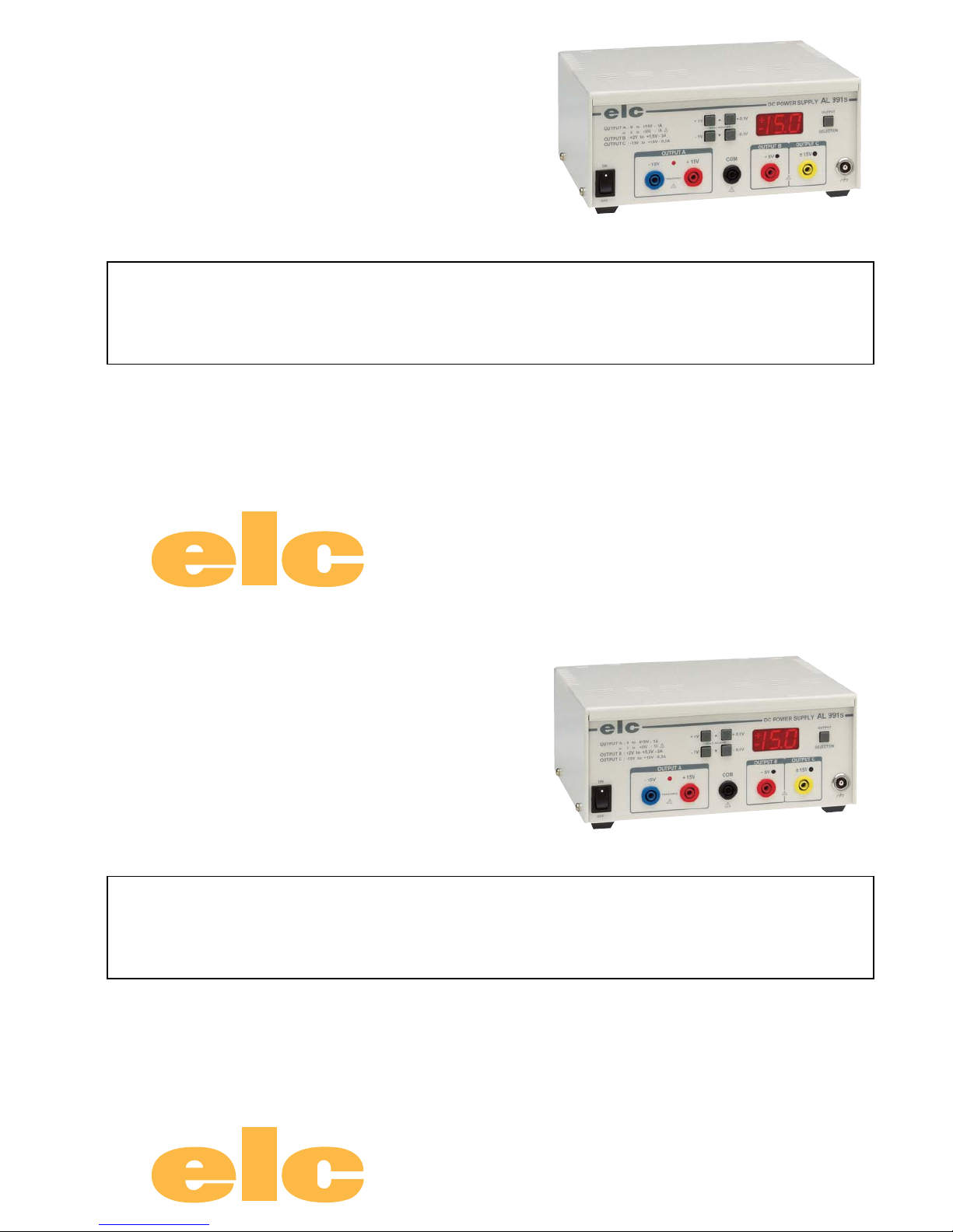
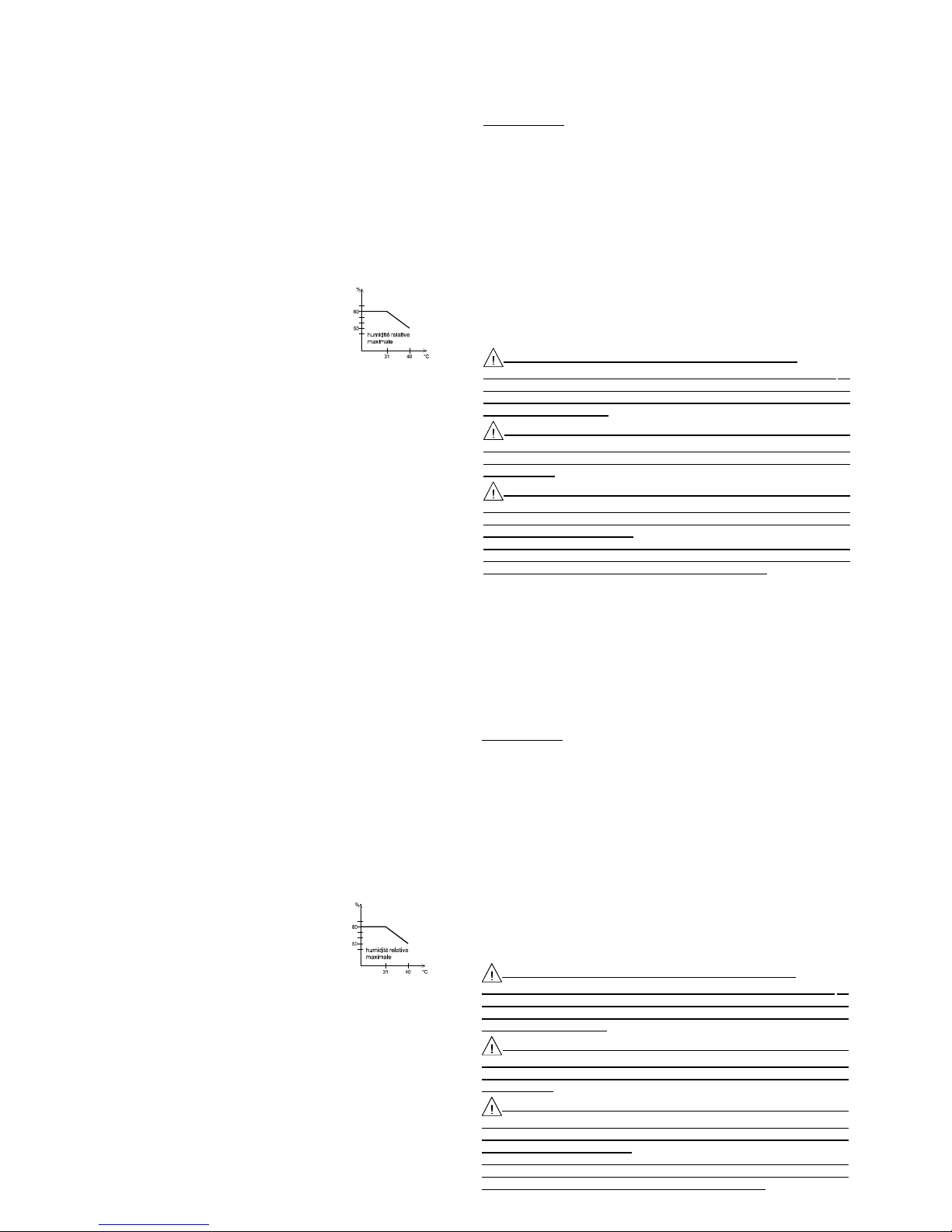
Vous venez d’acquérir l’ALIMENTATION STABILISEE elc type AL 991s. Nous vous
en remercions et vous félicitons de votre choix.
elc, c’est toute une gamme d’Alimentations mais aussi de nombreux appareils
électroniques : GÉNÉRATEURS DE FONCTIONS, FRÉQUENCEMÈTRE, APPAREILS DE TABLEAU...
Cet appareil a été construit conformément à la norme européenne EN 61010-1.
Leprésentmanueld’instructionscontientdestextesd’informationetd’avertissement
qui doivent être respectés par l’utilisateur, pour assurer un fonctionnement sûr et
pour maintenir l’appareil en bon état.
Cet appareil est destiné à un usage professionnel, industriel ou éducatif.
Cette alimentation à commande digitale se compose de trois alimentations.
2.2 CARACTERISTIQUES TECHNIQUES À 25° C
TENSION disponible en simultané
Trois alimentations : Alimentation A : réglable de 0 à ±15 Volts symétrique
Alimentation B : réglable de +2 à +5.5 Volts
Alimentation C : réglable de -15 à +15 Volts
Régulation : Alimentation A : < 20mV pour une variation de charge de 0 à100%
Alimentation B : < 30mV pour une variation de charge de 0 à100%
Alimentation C : < 400mV pour une variation de charge de 0 à100%
< 5mV pour une variation de ±10% secteur pour les trois
alimentations
Résistance interne : Alimentation A : < 20mΩ
Alimentation B : < 10mΩ
Alimentation C : < 200mΩ
Ondul. résiduelle : Alimentation A et C : < 4mV crête à crête ou 1,4mV efficace
Alimentation B : < 5mV crête à crête ou 1,8mV efficace
Visualisation : TroisLEDsrougesindiquentl'alimentationsélectionnéepour
l'affichage et le réglage.
Affichage : Afficheur numérique 3 digits de 14mm commun aux trois
alimentations
FRANCAIS
TABLE DES MATIERES
1 RENSEIGNEMENTS PRÉLIMINAIRES Page 3
2 DESCRIPTION Page 3
2.1 PRÉSENTATION Page 3
2.2 CARACTÉRISTIQUES TECHNIQUES Page 3
2.3 AUTRES CARACTÉRISTIQUES Page 4
2.4 COMPOSITION DE L’ENSEMBLE Page 4
3 INSTRUCTIONS PRÉLIMINAIRES Page 4
3.1 DÉBALLAGE ET RÉEMBALLAGE Page 4
3.2 MONTAGE ET MISE EN PLACE DE L’APPAREIL Page 4
4 PRÉPARATION AU FONCTIONNEMENT Page 4
5 INSTRUCTIONS POUR L’UTILISATION Page 4
5.1 PRESCRIPTIONS DE SÉCURITÉ Page 4
5.2 ORGANES DE COMMANDE Page 5
5.3 FONCTIONNEMENT Page 5
5.4 APPLICATIONS Page 6
6 PILOTAGE PAR ORDINATEUR Page 6
7 MAINTENANCE Page 6
8 SERVICE APRÈS VENTE Page 6
9 DECLARATION DE CONFORMITE Page 6
1. RENSEIGNEMENTS PRELIMINAIRES
Constructeur : elc 59 avenue des Romains 74000 ANNECY
Téléphone : +33 (0)4 50 57 30 46 Télécopie : +33 (0)4 50 57 45 19
Instrument : ALIMENTATION STABILISEE
Marque : elc
Type : AL 991s
2. DESCRIPTION
2.1 PRESENTATION
Vous venez d’acquérir l’ALIMENTATION STABILISEE elc type AL 991s. Nous vous
en remercions et vous félicitons de votre choix.
elc, c’est toute une gamme d’Alimentations mais aussi de nombreux appareils
électroniques : GÉNÉRATEURS DE FONCTIONS, FRÉQUENCEMÈTRE, APPAREILS DE TABLEAU...
Cet appareil a été construit conformément à la norme européenne EN 61010-1.
Leprésentmanueld’instructionscontientdestextesd’informationetd’avertissement
qui doivent être respectés par l’utilisateur, pour assurer un fonctionnement sûr et
pour maintenir l’appareil en bon état.
Cet appareil est destiné à un usage professionnel, industriel ou éducatif.
Cette alimentation à commande digitale se compose de trois alimentations.
2.2 CARACTERISTIQUES TECHNIQUES À 25° C
TENSION disponible en simultané
Trois alimentations : Alimentation A : réglable de 0 à ±15 Volts symétrique
Alimentation B : réglable de +2 à +5.5 Volts
Alimentation C : réglable de -15 à +15 Volts
Régulation : Alimentation A : < 20mV pour une variation de charge de 0 à100%
Alimentation B : < 30mV pour une variation de charge de 0 à100%
Alimentation C : < 400mV pour une variation de charge de 0 à100%
< 5mV pour une variation de ±10% secteur pour les trois
alimentations
Résistance interne : Alimentation A : < 20mΩ
Alimentation B : < 10mΩ
Alimentation C : < 200mΩ
Ondul. résiduelle : Alimentation A et C : < 4mV crête à crête ou 1,4mV efficace
Alimentation B : < 5mV crête à crête ou 1,8mV efficace
Visualisation : TroisLEDsrougesindiquentl'alimentationsélectionnéepour
l'affichage et le réglage.
Affichage : Afficheur numérique 3 digits de 14mm commun aux trois
alimentations
FRANCAIS
- 4 -
- 4 -
4000 4 195_Rev1 - 07/16 4000 4 195_Rev1 - 07/16
Résolution : 100mV
INTENSITE
I maximum : Alimentation A : 1 Ampère
Alimentation B : 3 Ampères à 5.5V et 1 Ampère à 2 V
Alimentation C : 0.2 Ampère
Visualisation : Clignotement de la ou les LEDS correpondant à (aux)
alimentation(s) en surcharge.
Affichage : La limitation d'intensité sur une alimentation provoque le
clignotement de l'afficheur. Celui-ci indique : Ic.A, Ic.B, Ic.C
+Ic. suivant la ou les sortie(s) en surcharge.
2.3 AUTRES CARACTERISTIQUES
Alimentation : Secteur 230V 50/60Hz. Fluctuation ±10%
Entrée secteur : Embase «EUROPE» CEE 22 avec cordon 2 pôles +
terre
Consommation max. : 130VA
Rigidité diélectrique : 2300VAC entre entrée et sortie
1350VAC entre entrée et châssis
500VDC entre sortie et châssis
Dimensions : L=215mm H=96mm P=200mm
Présentation : Façade polycarbonate sérigraphiée
Habillage ambre texturé
Masse : 3.9Kg
Condition d’utilisation : +5°C à +40°C
Condition de stockage : -10°C à +50°C
Condition d’humidité : Voir figure 1
PROTECTIONS
Classe de sécurité : I
Contre les courts-circuits : par limitation de courant.
Contre toute surintensité au transformateur : par fusible au primaire
NORMES
CEM EN 55011 groupe 1 Classe B
EN 50082-1 Critère d’aptitude A
SECURITE EN 61010-1
Catégorie de surtension II et degré de pollution 2
2.4 COMPOSITION DE L’ENSEMBLE
VotrealimentationAL991svousestlivréeavecsoncordonsecteurfiche«EUROPE»
2 pôles + terre et son manuel d’instructions.
3 INSTRUCTIONS PRELIMINAIRES
3.1 DEBALLAGE ET RÉEMBALLAGE
L’alimentation, lors de son transport, est protégée par un emballage cartonné afin
d’éviter tous dommages.
Conservez-le il pourra être utile ultérieurement.
Liste de colisage :
1 manuel d’instructions 1 sac plastique 1 cordon secteur
1 alimentation : AL991s 2 cales en carton
3.2 MONTAGE ET MISE EN PLACE DE L’APPAREIL
Pour une bonne convection naturelle, l’alimentation doit reposer sur ses 4 butées
caoutchouc et toutes les ouvertures d’aération doivent être largement dégagées.
Brancher le cordon secteur dans l’embase «EUROPE» CEE22 à l’arrière de
l’appareil.
4 PREPARATION AU FONCTIONNEMENT
Raccorder l’alimentation au réseau 230V et mettre sous tension avec l’interrupteur
Marche/Arrêt.
5 INSTRUCTIONS POUR L’UTILISATION
5.1 PRESCRIPTIONS DE SECURITE
Aucune intervention n’est autorisée à l’intérieur de l’appareil.
L’appareil doit être utilisé conformément aux instructions de ce document. La
prise du cordon secteur étant utilisée comme le dispositif de sectionnement,
l’appareil doit être raccordé sur un socle de prise aisément accessible et
devant comporter la terre.
Lorsque cet appareil doit être alimenté par l’intermédiaire d’un
autotransformateur séparé en vue d’une réduction de la tension, veiller à ce
que la borne commune soit raccordée au pôle mis à la terre du circuit
d’alimentation.
Toutes les sorties sont flottantes par rapport à la terre. La tension
maximale de mode commun admissible entre la terre et les sorties est de 50V
efficace. Une tension jugée dangereuse (> 60 Vdc) peut être atteinte entre l’une
des bornes de sortie et la terre.
Dans ce cas, il est impératif d’utiliser des cordons de sécurité pour le
raccordement aux sorties de l’appareil. De plus, les appareils raccordés ne
doivent pas présenter de parties conductrices accessibles.
FRANCAIS
Fig. 1
- 5 -
- 5 -
4000 4 195_Rev1 - 07/16 4000 4 195_Rev1 - 07/16
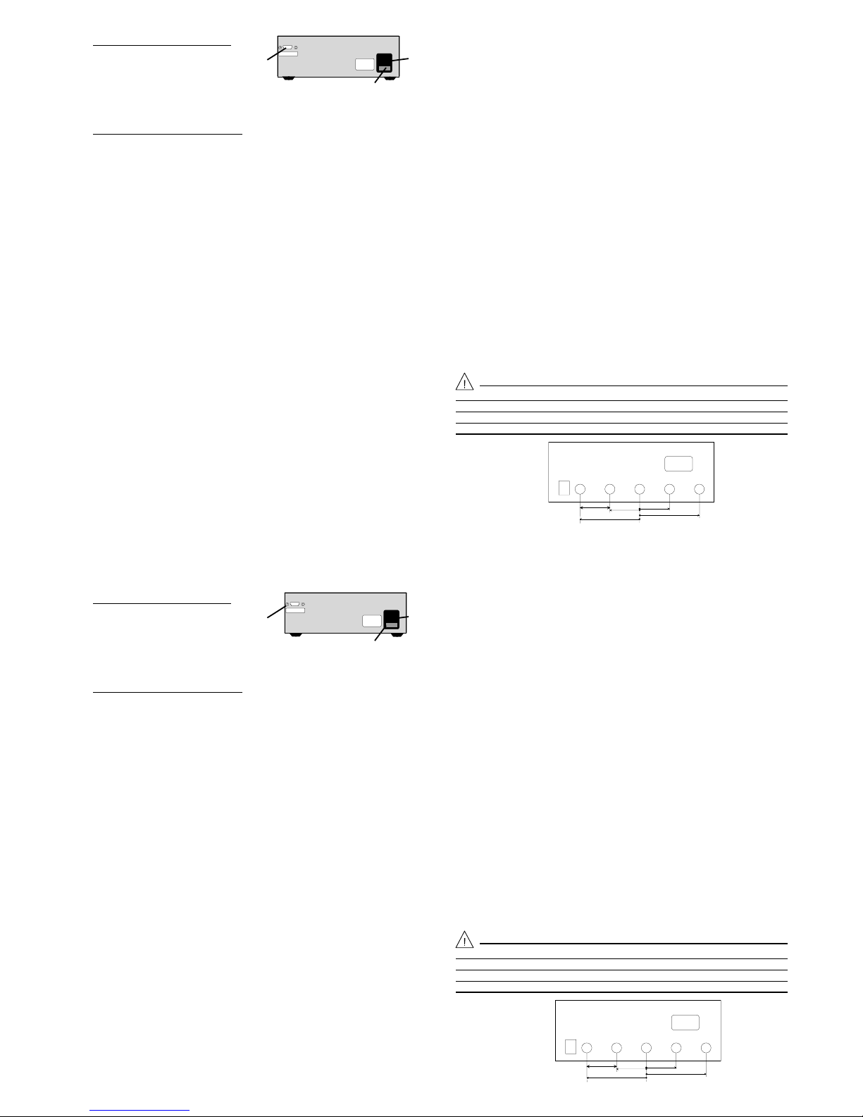
5.2 ORGANES DE COMMANDE
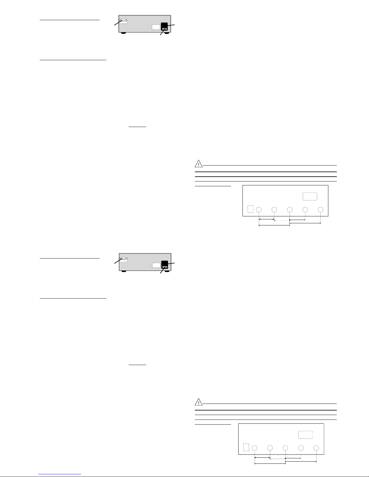
5.2.1 Description de la face arrière
A: PRISE LIAISON SERIE RS232
B: EMBASE SECTEUR
C: PORTE FUSIBLE avec FUSIBLE T1.6A
Le fusible (5 x 20mm T1.6A) doit être remplacé par
un fusible de même type et de mêmes caractéristiques.
5.2.2 Vue d’ensemble de la face avant
(1) INTERRUPTEUR MARCHE / ARRET. Position on, l'alimentation est sous
tension. Position off, l'alimentation est arrêtée.
(2) DOUILLES DE SORTIE A. Elles fournissent deux tensions symétriques
réglables de 0 à ±15V avec un courant de 1A par rapport à la borne COM
(4) ou 0 à +30V par rapport à la borne -15V .
(3) TEMOIN DE SELECTION SORTIE A. Le témoin éclairé indique que la sortie
A est sélectionnée pour le réglage et la visualisation de sa valeur sur
l'afficheur (10).Indiqueégalementparsonclignotementquecettesortie est en
surcharge.
(4) DOUILLE COMMUNE. Borne de référence commune à toute les sorties.
(5) DOUILLE DE SORTIE B. Fournit une tension réglable de +2V à +5.5V
avec un courant max. compris entre 1A et 3A.
(6) TEMOIN DE SELECTION SORTIE B. Le témoin éclairé indique que la sortie
B est sélectionnée pour le réglage et la visualisation de sa valeur sur
l'afficheur (10). Indique également par son clignotement que cette sortie est
en surcharge.
(7) DOUILLE DE SORTIE C. Fournit une tension réglable de -15V à +15V
avec un courant max. de 0.2A.
(8) TEMOINDE SELECTION SORTIE C. Letémoin éclairé indique que la sortie
C est sélectionnée pour le réglage et la visualisation de sa valeur sur
l'afficheur (10). Indique également par son clignotement que cette sortie est
en surcharge.
(9) DOUILLE DE TERRE FONCTIONNELLE INVERSEE. Permet de
référencer votre montage à la terre. Cette douille est directement reliée à la
terre par le chassis.
(10) SELECTION DES SORTIES. Permet le choix de la sortie à afficher. Une
impulsion sur le bouton décale d'une sortie dans le sens A - B - C - A ...
(11) AFFICHEUR. Affiche la valeur de la sortie sélectionée par (9). Indique
également si les sorties sont en surcharge.
(12) REGLAGE DE TENSION + 0.1V. Une impulsion sur le bouton augmente la
tension de la sortie sélectionnée de 0.1V.
(13) REGLAGE DE TENSION - 0.1V. Une impulsion sur le bouton diminue la
tension de la sortie sélectionnée de 0.1V.
(14) REGLAGE DE TENSION + 1V. Une impulsion sur le bouton augmente la
tension de la sortie sélectionnée de 1V.
(15) REGLAGE DE TENSION - 1V. Une impulsion sur le bouton diminue la
tension de la sortie sélectionnée de 1V.
5.3 FONCTIONNEMENT
- A la mise sous tension, l'alimentation se positionne sur la sortie qui était
sélectionnée lors de l'utilisation précédente. Toutes les tensions réglées sont
mémorisées automatiquement. Ainsi en cas d'arrêt imprévu ou de coupure
secteur, les réglages sont conservés lors de la remise sous tension.
- Sélectionner la sortie à régler avec le bouton (10) et les témoins (3), (6) et (8).
- Régler la tension avec les boutons (12) à (15).
- Connecter la charge entre la borne COM et celle de la sortie réglée.
- Répéter l'opération pour les autres sorties.
Toutes les sorties sont disponibles simultanément. Vous pouvez régler une sortie
pendant que les autres sont en fonctionnement.
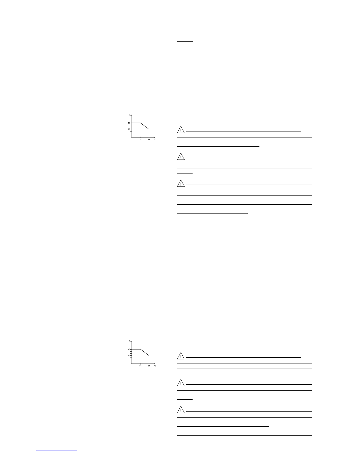
Pour disposer d'une alimentation réglable de 0 à +30V, il faut se connecter
entre les douilles -15V et +15V. Dans cette configuration, vous ne pouvez plus
utiliser les deux autres alimentations sur le même montage, car la référence
n'est plus la même. La valeur sur l'afficheur ainsi que le réglage sont à
multiplier par deux.
FRANCAIS
C
Fig. 2
AB
COMSORTIE A SORTIE B SORTIE C
0 à +15V
0 à -15V
+2V à +5.5V
-15V à +15V
0 à +30V
5.2 ORGANES DE COMMANDE
5.2.1 Description de la face arrière
A: PRISE LIAISON SERIE RS232
B: EMBASE SECTEUR
C: PORTE FUSIBLE avec FUSIBLE T1.6A
Le fusible (5 x 20mm T1.6A ) doit être remplacé par
un fusible de même type et de mêmes caractéristiques.
5.2.2 Vue d’ensemble de la face avant
(1) INTERRUPTEUR MARCHE / ARRET. Position on, l'alimentation est sous
tension. Position off, l'alimentation est arrêtée.
(2) DOUILLES DE SORTIE A. Elles fournissent deux tensions symétriques
réglables de 0 à ±15V avec un courant de 1A par rapport à la borne COM
(4) ou 0 à +30V par rapport à la borne -15V .
(3) TEMOIN DE SELECTION SORTIE A. Le témoin éclairé indique que la sortie
A est sélectionnée pour le réglage et la visualisation de sa valeur sur
l'afficheur (10).Indique également par sonclignotementquecettesortie est en
surcharge.
(4) DOUILLE COMMUNE. Borne de référence commune à toute les sorties.
(5) DOUILLE DE SORTIE B. Fournit une tension réglable de +2V à +5.5V
avec un courant max. compris entre 1A et 3A.
(6) TEMOIN DE SELECTION SORTIE B. Le témoin éclairé indique que la sortie
B est sélectionnée pour le réglage et la visualisation de sa valeur sur
l'afficheur (10). Indique également par son clignotement que cette sortie est
en surcharge.
(7) DOUILLE DE SORTIE C. Fournit une tension réglable de -15V à +15V
avec un courant max. de 0.2A.
(8) TEMOINDE SELECTION SORTIE C. Letémoin éclairé indique que la sortie
C est sélectionnée pour le réglage et la visualisation de sa valeur sur
l'afficheur (10). Indique également par son clignotement que cette sortie est
en surcharge.
(9) DOUILLE DE TERRE FONCTIONNELLE DE SECURITE. Permet de
référencer votre montage à la terre. Cette douille est directement reliée à la
terre par le chassis.
(10) SELECTION DES SORTIES. Permet le choix de la sortie à afficher. Une
impulsion sur le bouton décale d'une sortie dans le sens A - B - C - A ...
(11) AFFICHEUR. Affiche la valeur de la sortie sélectionée par (9). Indique
également si les sorties sont en surcharge.
(12) REGLAGE DE TENSION + 0.1V. Une impulsion sur le bouton augmente la
tension de la sortie sélectionnée de 0.1V.
(13) REGLAGE DE TENSION - 0.1V. Une impulsion sur le bouton diminue la
tension de la sortie sélectionnée de 0.1V.
(14) REGLAGE DE TENSION + 1V. Une impulsion sur le bouton augmente la
tension de la sortie sélectionnée de 1V.
(15) REGLAGE DE TENSION - 1V. Une impulsion sur le bouton diminue la
tension de la sortie sélectionnée de 1V.
5.3 FONCTIONNEMENT
- A la mise sous tension, l'alimentation se positionne sur la sortie qui était
sélectionnée lors de l'utilisation précédente. Toutes les tensions réglées sont
mémorisées automatiquement. Ainsi en cas d'arrêt imprévu ou de coupure
secteur, les réglages sont conservés lors de la remise sous tension.
- Sélectionner la sortie à régler avec le bouton (10) et les témoins (3), (6) et (8).
- Régler la tension avec les boutons (12) à (15).
- Connecter la charge entre la borne COM et celle de la sortie réglée.
- Répéter l'opération pour les autres sorties.
Toutes les sorties sont disponibles simultanément. Vous pouvez régler une sortie
pendant que les autres sont en fonctionnement.
Pour disposer d'une alimentation réglable de 0 à +30V, il faut se connecter
entre les douilles -15V et +15V. Dans cette configuration, vous ne pouvez plus
utiliser les deux autres alimentations sur le même montage, car la référence
n'est plus la même. La valeur sur l'afficheur ainsi que le réglage sont à
multiplier par deux.
FRANCAIS
C
Fig. 2
AB
COMSORTIE A SORTIE B SORTIE C
0 à +15V
0 à -15V
+2V à +5.5V
-15V à +15V
0 à +30V

- 6 -
- 6 -
4000 4 195_Rev1 - 07/16 4000 4 195_Rev1 - 07/16
En cas de surcharge, le témoin de la (des) sortie(s) concernée(s) clignote ainsi que
l'afficheur. Celui-ci affiche Ic.A, Ic.B, Ic.C ou +Ic. suivant la (les) sortie(s) en
surcharge, même si la sortie en surcharge n'était pas celle sélectionnée.
5.3.1 Précautions
Toujoursrégler l’alimentation avantd’appliquer la charge.Connecter lacharge avec
des cordons isolés de diamètre suffisant. Déconnecter la charge avant l’arrêt de
l’alimentation. Stocker l’appareil à l’abri de la poussière.
Toute interruption du conducteur de protection, à l’extérieur de l’appareil,
ou débranchement de la borne de terre risque de rendre l’appareil dangereux.
L’interruption intentionnelle est interdite.
5.4 APPLICATIONS
Votrealimentation,deparsaconception,répondàlagrandemajoritédevosbesoins.
AveclasortieA,vouspouvezalimentertouslesmontagesnécéssitantdeuxtensions
symétriques comme les circuits à amplificateur opérationnel ou les composants de
convertion numérique - analogique (et inversement) qui sont de plus en plus utilisés.
En configuration 30V, vous disposez d'une alimentation universelle. Dans ce cas,
n'oubliez pas que votre montage est alimenté par rapport au bornes -15V et +15V.
Vous ne pourrez plus utiliser les alimentations B et C sur le même montage, car elles
n'auront pas la même référence.
La sortie B répond à la demande des composants de nouvelle génération type
microprocesseuroulogique programmable. Ces composants s'alimentent sous des
tensions de plus en plus faibles avec des courants parfois élevés.Les commandes
digitales apportent un confort pour régler des tensions de 3.3V ou 2.7V par exemple.
Elle pourra aussi alimenter, plus classiquement, tous les composants de type TTL.
Enfinla sortie C vous permetde disposer d'unetension négative oupositive très utile
pour caractériser des composants tels que diode ou transistor par exemple.
Les alimentations A+B+C vous permettent donc d'alimenter directement des cartes
mixtes (analogique / digitale), où des tensions comme +12V, -12V +5V et -5V sont
souvent requises.
6 PILOTAGE PAR ORDINATEUR
Vous pouvez piloter votre alimentation grâce aux logiciels LG 991S (à télécharger
sur le site elc.fr) et la liaison RS232 située à l'arrière de l'appareil. Pour la connection
il faut vous munir d'un câble NULL-MODEM blindé d'une longueur maximale de 15
mètres. Le brochage du connecteur se trouve à l'arrière de l'appareil. Après avoir
effectué les connections, installer le logiciel en suivant les instructions. Mettre
l'alimentation sous tension et démarrer le logiciel. Vous pouvez alors commander
votre alimentation depuis votre ordinateur et créer des séquences automatisées.
Pour la maîtrise du logiciel et la définition des codes commandes reportez-vous à
l'aide en ligne.
7 MAINTENANCE
Aucun entretien particulier n’est à envisager pour cet appareil.
Eviter la poussière, l’humidité, les chocs, votre appareil vous en sera reconnaissant.
Pour le nettoyage, utiliser un chiffon doux à poussière.
Si l'afficheur ne s’allume pas à la mise sous tension, vérifier :
- Si l’interrupteur on-off est enfoncé
- La présence de la tension secteur
- Le raccordement au réseau
- Le fusible de protection (5x20 T1.6A).
8 SERVICE APRES-VENTE
Le Service après-vente est assuré par la Société elc.
La période de garantie est de deux ans pièces et main-d’oeuvre. Ne sont toutefois
pasgarantislespannesoudéfautsprovenantd’unemauvaiseutilisationdel’appareil
(tensionsecteur non conforme, chocs ...)ou ayant étédépanné hors de nosservices
ou des ateliers de nos agences autorisées.
9 DECLARATION UE DE CONFORMITE
Fabricant : elc
Adresse : 59 avenue des Romains 74000 Annecy France
déclare que le produit
Nom : Alimentation stabilisée
Numéro : AL 991s
est conforme aux exigences des Directives : Basse Tension 2014/35/UE,
Compatibilité Electromagnétique 2014/30/UE et RoHs 2011/65/UE.
Les normes harmonisées suivantes ont été appliquées :
Sécurité : EN61010-1:2010
CEM : EN61326-1:2013
Annecy le 06/07/2016 Henri Curri, gérant
FRANCAIS

- 7 -
- 7 -
4000 4 195_Rev1 - 07/16 4000 4 195_Rev1 - 07/16
TABLE OF CONTENTS
1 PRELIMINARY INFORMATION Page 7
2 DESCRIPTION Page 7
2.1 INTRODUCTION Page 7
2.2TECHNICAL SPECIFICATIONS Page 7
2.3 OTHER SPECIFICATIONS Page 8
2.3 ACCESSORIES OF THE INSTRUMENT Page 8
3 PRELIMINARY INSTRUCTIONS Page 8
3.1 PACKAGING Page 8
3.2 MOUNTING AND PLACING OF THE INSTRUMENT Page 8
4 BEFORE USE Page 8
5 INSTRUCTIONS FOR USE Page 8
5.1 SAFETY INSTRUCTIONS Page 8
5.2 CONTROLS Page 9
5.3 WORKING Page 9
5.4 APPLICATIONS Page 10
6 REMOTE SENSING AND VOLTAGE PROGRAMMING Page 10
7 MAINTENANCE Page 10
8 AFTER SALES SERVICE Page 10
9 DECLARATION OF CONFORMITY Page 10
1. PRELIMINARY INFORMATION
Manufacturer : elc 59 avenue des Romains 74000 ANNECY - FRANCE
Phone : + 33 (0)4 50 57 30 46 Fax : +33 (0)4 50 57 45 19
Instrument : STABILIZED POWER-SUPPLY
Trademark : elc
Type : AL 991s
2. DESCRIPTION
2.1 INTRODUCTION
You just bought the POWER SUPPLY Type elc AL 991s. We thank you and
congratulate you for your good choice.
The elc company proposes a wide range of POWER SUPPLIES and many other
electronic test instruments : LF AND FUNCTION GENERATORS, FREQUENCYMETER, ....
This instrument has been conceived according to the European standard EN 61010-1
and supplied in good condition. This instructions manual contains information and
notes, which must be respected by the user, in order to ensure a safe working and
to maintain the instrument in good condition.
This instrument is intended for a professional, industrial and educational use.
This power supply with digital display is made up of three power supplies.
2.2 TECHNICAL SPECIFICATIONS AT 25°C
VOLTAGE available simultaneously
3 Power Supplies : Output A : adjustable from 0 to ±15 Volts tracking
Output B: adjustable from +2 to +5.5 Volts
Output C: adjustable from -15 to +15 Volts
Regulation : Output A: < 20mV for a load variation from 0 à100%
Output B: < 30mV for a load variation from 0 à100%
Output C: < 400mV for a load variation from 0 à100%
< 5mVfor a mainsvariation of±10% forthe 3power supplies
Internal resistance : Output A: < 20mΩ
Output B: < 10mΩ
Output C: < 200mΩ
Ripple : Output A and C : < 3mV peak to peak or 1mV rms
Output C : < 5mV peak to peak or 1.8mV rms
Signalling : Three red LEDs indicate the power supply selected for
display and setting
Display : Digital indicator with 3 digits of 14mm, common to the 3
power supplies
ENGLISH

- 8 -
- 8 -
4000 4 195_Rev1 - 07/16 4000 4 195_Rev1 - 07/16
Resolution : 100mV
CURRENT
Maxi I : Output A: 1 A
Output B: 3 A at 5.5V and 1 A at 2 V
Output C: 0.2 A
Signalling : Flashing of the LED(s) relating to the power supply(ies) in
overload.
Display : The curentlimitinginonepower supply makes the indicatorflash
It indicates : Ic.A, Ic.B, Ic.C or +Ic depending on the output(s)
in overload.
2.3 OTHER SPECIFICATIONS
Mains : 230V 50 / 60Hz. Variation of ±10%
Mains input : «EUROPE» CEE 22 receptacle with bipolar cord + Earth
Maxi consumption : 130VA
Electric strength : 2300VAC between input and output
1350VAC between input and frame
500VDC between output and frame
Dimensions : L = 215mm H = 96mm D = 200mm
Appearance : Polycarbonate front silk-screen printed, amber coloured
face
Weight : 3.9 kg
Condition of use : +5°C to +40°C
Condition of storage : -10°C to +50°C
Condition of moisture : See diagram
PROTECTIONS
Safety class : I
Against short-circuits : by current limiting.
Against any overcurrent
in the transformer : by fuse in the primary winding.
STANDARD
EMC EN 55011 group 1 class B
EN 55082-1 performance criterion A
SAFETY EN 61010-1
Overvoltage category II and pollution degree 2
2.4 ACCESSORIES OF THE INSTRUMENT
Your AL 991s power-supply is delivered with its mains cord «EUROPE» bipolar plug
+ Earth and its instructions manual.
3. PRELIMINARY INSTRUCTIONS
3.1 PACKAGING
During its transport, the power-supply is protected by a cardboard box avoiding any
damage. Keep this material ; you may use it later on.
Packing list :
1 instructions manual 1 plastic bag 1 mains cord
1 power-supply : AL991s 2 cardboard packing pieces
3.2 MOUNTING AND PLACING OF THE INSTRUMENT
For a natural and correct cooling, the power supply must stand on its four rubber
thrusts and all ventilation openings must be widely cleared.
Connect the mains cord in the «EUROPE» CEE22 receptacle at the rear of the
instrument.
4. BEFORE USE
To connect the power supply to mains (230V) and to switch on with the «On/Off»
switch.
5. INSTRUCTIONS FOR USE
5.1 SAFETY INSTRUCTIONS
None intervention is authorized inside the casing.
The instrument must be used according to the instructions of this manual. The
plug of the mains cord being used as the switch off device, the instrument must
be connected to a socket easily accessible, which has an earth connection.
When this instrument has to be powered using a separated autotransformer
in order to get a voltage reduction, make sure that the common terminal is
connected to the earthed pole of the feeding circuit.
All the outputs float with reference to the earth. The maximum permissible
common mode voltage between Earth and outputs amounts to 50V rms. A
voltage judged dangerous (>60V =) can be reached between one of the output
terminals and earth.
In this case, it is necessary to use safety cords for the connection to the
instrument’s outputs. Moreover, the instruments connected mustn’t give
access to conductive parts.
maximum relative
moisture
ENGLISH

- 9 -
- 9 -
4000 4 195_Rev1 - 07/16 4000 4 195_Rev1 - 07/16
5.2 CONTROLS
5.2.1 Description of the rear panel
A: RS 232 SOCKET
A: MAINS RECEPTACLE
B: FUSEHOLDER with T1.6A FUSE
The fuse (5 x 20mm T1.6A ) can be replaced by a
fuse of same type and features.
5.2.2 Controls description of the front panel
(1) «ON-OFF» SWITCH. "On" position, the power supply can work. "OFF"
position, the power supply can not work.
(2) A OUTPUT SOCKETS. They give 2 symmetrical voltages, adjustable from
0 to ±15V with a current of 1A with reference to the COM terminal (4) or from
0 to 30V with reference to the -15V terminal.
(3) SELECTION WARNING LED OF THE A OUTPUT. The switched on led
indicates the selection of the A output for setting and display of its value with
the indicator (10). Indicates also by its flashing that this output is in overload.
(4) COMMON SOCKET. Reference terminal common to all outputs.
(5) B OUTPUT SOCKET. Provides a voltage adjustable from +2V to +5.5V with
a maxi current between 1 and 3A.
(6) SELECTION WARNING LED OF THE B OUTPUT. The switched on led
indicates the selection of the B output for setting and display of its value with
the indicator (10). Indicates also by its flashing that this output is in overload.
(7) C OUTPUT SOCKET. Provides a voltage adjustable from -15V to +15V with
a maxi current of 0.2A.
(8) SELECTION WARNING LED OF THE C OUTPUT. The switched on led
indicates the selection of the C output for setting and display of its value with
the indicator (10). Indicates also by its flashing that this output is in overload.
(9) SAFETY FUNCTIONAL EARTH SOCKET. Allows to take the Earth as
reference for your mounting. This socket is directly earthed from the frame.
(10) OUTPUTS SELECTION. Allows to choose the output to be displayed. A
press on the button makes the selection move in the way A - B - C - A - ...
(11) INDICATOR. Displays the value of the output selected by (9). Indicates also
if the outputs are in overload.
(12) +0.1V VOLTAGE SETTING. A press on the button increases the voltage
of the selected output of 0.1V.
(13) -0.1V VOLTAGE SETTING. A press on the button decreases the voltage
of the selected output of 0.1V.
(14) +1V VOLTAGE SETTING. A press on the button increases the voltage
of the selected output of 1V.
(15) -1V VOLTAGE SETTING. A press on the button decreases the voltage
of the selected output of 1V.
5.3 WORKING
On the swiching on, the power supply provides the output value, which was selected
on the previous use. All adjusted voltages are stored automatically. So, in the case
of an unforeseen stop or a supply disconnection, the settings are maintained, when
the power supply is switched on again.
- To select the output to set with the (9) button and the (3), (6), and (8) warning leds.
- To select the voltage with the (11) to (14) buttons.
- To connect the load between the COM terminal and the one of the adjusted output.
- To repeat the process for the other outputs.
All outputs are available simultaneously. An output can be adjusted, while the other
ones work.
In order to have a power supply adjustable from 0 to+30V, you have to
connect the load between the -15V and +15V sockets. In this configuration, you
can not use the 2 other power supplies with the same mounting anymore,
because the reference is not the same. You have to multiply the value on the
indicator, as well as the setting by two.
A
B
C
COMOUTPUT A OUTPUT B OUTPUT C
0 to +15V
0 to -15V
+2V t o +5.5V
-15V to +15V
0 to 30V
ENGLISH
5.2 CONTROLS
5.2.1 Description of the rear panel
A: RS 232 SOCKET
A: MAINS RECEPTACLE
B: FUSEHOLDER with T1.6A FUSE
The fuse (5 x 20mm T1.6A ) can be replaced by a
fuse of same type and features.
5.2.2 Controls description of the front panel
(1) «ON-OFF» SWITCH. "On" position, the power supply can work. "OFF"
position, the power supply can not work.
(2) A OUTPUT SOCKETS. They give 2 symmetrical voltages, adjustable from
0 to ±15V with a current of 1A with reference to the COM terminal (4) or from
0 to 30V with reference to the -15V terminal.
(3) SELECTION WARNING LED OF THE A OUTPUT. The switched on led
indicates the selection of the A output for setting and display of its value with
the indicator (10). Indicates also by its flashing that this output is in overload.
(4) COMMON SOCKET. Reference terminal common to all outputs.
(5) B OUTPUT SOCKET. Provides a voltage adjustable from +2V to +5.5V with
a maxi current between 1 and 3A.
(6) SELECTION WARNING LED OF THE B OUTPUT. The switched on led
indicates the selection of the B output for setting and display of its value with
the indicator (10). Indicates also by its flashing that this output is in overload.
(7) C OUTPUT SOCKET. Provides a voltage adjustable from -15V to +15V with
a maxi current of 0.2A.
(8) SELECTION WARNING LED OF THE C OUTPUT. The switched on led
indicates the selection of the C output for setting and display of its value with
the indicator (10). Indicates also by its flashing that this output is in overload.
(9) SAFETY FUNCTIONAL EARTH SOCKET. Allows to take the Earth as
reference for your mounting. This socket is directly earthed from the frame.
(10) OUTPUTS SELECTION. Allows to choose the output to be displayed. A
press on the button makes the selection move in the way A - B - C - A - ...
(11) INDICATOR. Displays the value of the output selected by (9). Indicates also
if the outputs are in overload.
(12) +0.1V VOLTAGE SETTING. A press on the button increases the voltage
of the selected output of 0.1V.
(13) -0.1V VOLTAGE SETTING. A press on the button decreases the voltage
of the selected output of 0.1V.
(14) +1V VOLTAGE SETTING. A press on the button increases the voltage
of the selected output of 1V.
(15) -1V VOLTAGE SETTING. A press on the button decreases the voltage
of the selected output of 1V.
5.3 WORKING
On the swiching on, the power supply provides the output value, which was selected
on the previous use. All adjusted voltages are stored automatically. So, in the case
of an unforeseen stop or a supply disconnection, the settings are maintained, when
the power supply is switched on again.
- To select the output to set with the (9) button and the (3), (6), and (8) warning leds.
- To select the voltage with the (11) to (14) buttons.
- To connect the load between the COM terminal and the one of the adjusted output.
- To repeat the process for the other outputs.
All outputs are available simultaneously. An output can be adjusted, while the other
ones work.
In order to have a power supply adjustable from 0 to+30V, you have to
connect the load between the -15V and +15V sockets. In this configuration, you
can not use the 2 other power supplies with the same mounting anymore,
because the reference is not the same. You have to multiply the value on the
indicator, as well as the setting by two.
A
B
C
COMOUTPUT A OUTPUT B OUTPUT C
0 to +15V
0 to -15V
+2V to +5.5V
-15V to +15V
0 to 30V
ENGLISH

- 10 -
- 10 -
4000 4 195_Rev1 - 07/16 4000 4 195_Rev1 - 07/16
In the case of an overload, the warning Led of the output(s) concerned flashes, as
well as the indicator. This one displays Ic.A, Ic.B, Ic.C or +Ic. according to the
output(s) in overload, even if the output in overload is not the selected one.
5.3.1 Cautions
Before applying the load, to always set the power supply. To connect the load using
insulated cords with sufficient diameter. To disconnect the load, before switching off
the power supply. To keep the instrument away from dust.
Any interruption of the protective conductor outside the case or any
disconnecting of the earth terminal may render the instrument dangerous.
The intentional interruption is forbidden.
5.4 APPLICATIONS
Your power supply type AL 991s meets most of your needs.
With the A output, you can feed all mountings requiring 2 symmetrical voltages, like
circuitswith operational amplifier or digitalto analogue conversion components(and
inversely), which are more and more used.
Inthe30Vconfiguration,youhaveauniversalpowersupply.Inthiscase,donotforget
that your mounting is feeded with reference to the -15V or +15V terminals.
You will not be able to use the B and C power supplies with the same mounting
anymore, because they will not have the same reference.
The B output meets the requirement of the components of new generation type
microprocessor or programmable logic. These components feed themselves with
lower and lower voltages and sometimes high currents. The digital controls bring
ease in the adjustment of 3.3V or 2.7V voltages for example.
More classically, it will also be able to feed all TTL components.
The C output enables you to have a very useful negative or positive voltage, in order
to characterize components, such as diode or transistor for example.
The A+B+C power supplies enable you to feed directly combined analogue/digital
boards, where voltages like +12V, -12V, +5V and -5V are often required.
6. REMOTE SENSING - VOLTAGE PROGRAMMING
Youcanuseyourpower supply in this way thanks to the softwareLG991S (download
the software in our website : elc.fr) and to the socket RS232 mounted in the
instrument's rear. For the connection, you have to use a screened cable NULL-
MODEM with a maximum lenght of 15 meters. The connector has to be pinned in the
instrument's rear. After the connection have been done, to install the software
accordingtotheinstructions. To switch the power supply on andto start the software.
Then, you can use your power supply from your computer and generate automated
events.Inordertomasterthesoftwareandthedefinitionofthecontrolscodes,please
refer to the help on line.
7. MAINTENANCE
No particular maintenance is required for this instrument.
To avoid dust, moisture, shocks ; your instrument will be grateful for that.
For the cleaning, please use a smooth duster.
If indicator do not light up on switching on, to check :
- That the «ON/OFF» switch is pressed
- The mains voltage
- The connection to mains
- The protective fuse (5x20 T1.6A).
8. AFTER SALES SERVICE
The after sales Service is ensured by the elc company.
Duringtwoyears, spare parts and workmanship are guaranteed.Thisguaranteedoes
not apply to instruments presenting defects or failures caused by an improper use
(wrong mains voltage, shocks ...) or which have been repaired outside our factory or
the repair shops of our authorized agencies.
9. EU DECLARATION OF CONFORMITY
Manufacturer : elc
Address : 59, av. des Romains - 74000 Annecy - France
declares the product
Name : StabilizedPower-supply
Number : AL991s
conformable to the requirements of the directives :
Low voltage 2014/35/UE, Electromagnetic Compatibility 2014/30/UE and
RoHs2011/65/UE.
The following harmonized standards have been applied :
Safety : EN61010-1:2010
EMC : EN61326-1:2013
Annecy, on July 6, 2016 H. CURRI Manager
ENGLISH
Inthecaseofanoverload,thewarningLedoftheoutput(s)concernedflashes,aswell
as the indicator. This one displays Ic.A, Ic.B, Ic.C or +Ic. according to the output(s)
in overload, even if the output in overload is not the selected one.
5.3.1 Cautions
Before applying the load, to always set the power supply. To connect the load using
insulated cords with sufficient diameter. To disconnect the load, before switching off
the power supply. To keep the instrument away from dust.
Any interruption of the protective conductor outside the case or any
disconnecting of the earth terminal may render the instrument dangerous.
The intentional interruption is forbidden.
5.4 APPLICATIONS
Your power supply type AL 991s meets most of your needs.
With the A output, you can feed all mountings requiring 2 symmetrical voltages, like
circuitswith operational amplifier or digitalto analogue conversion components(and
inversely), which are more and more used.
Inthe30Vconfiguration,youhaveauniversalpowersupply.Inthiscase,donotforget
that your mounting is feeded with reference to the -15V or +15V terminals.
You will not be able to use the B and C power supplies with the same mounting
anymore, because they will not have the same reference.
The B output meets the requirement of the components of new generation type
microprocessor or programmable logic. These components feed themselves with
lower and lower voltages and sometimes high currents. The digital controls bring
ease in the adjustment of 3.3V or 2.7V voltages for example.
More classically, it will also be able to feed all TTL components.
The C output enables you to have a very useful negative or positive voltage, in order
to characterize components, such as diode or transistor for example.
The A+B+C power supplies enable you to feed directly combined analogue/digital
boards, where voltages like +12V, -12V, +5V and -5V are often required.
6. REMOTE SENSING - VOLTAGE PROGRAMMING
Youcanuseyourpower supply in this way thanks to the softwareLG991S (download
the software in our website : elc.fr) and to the socket RS232 mounted in the
instrument's rear. For the connection, you have to use a screened cable NULL-
MODEM with a maximum lenght of 15 meters. The connector has to be pinned in the
instrument's rear. After the connection have been done, to install the software
accordingtotheinstructions. To switch the power supply on andto start the software.
Then, you can use your power supply from your computer and generate automated
events.Inordertomasterthesoftwareandthedefinitionofthecontrolscodes,please
refer to the help on line.
7. MAINTENANCE
No particular maintenance is required for this instrument.
To avoid dust, moisture, shocks ; your instrument will be grateful for that.
For the cleaning, please use a smooth duster.
If indicator do not light up on switching on, to check :
- That the «ON/OFF» switch is pressed
- The mains voltage
- The connection to mains
- The protective fuse (5x20 T1.6A).
8. AFTER SALES SERVICE
The after sales Service is ensured by the elc company.
Duringtwoyears, spare parts and workmanship are guaranteed.Thisguaranteedoes
not apply to instruments presenting defects or failures caused by an improper use
(wrong mains voltage, shocks ...) or which have been repaired outside our factory or
the repair shops of our authorized agencies.
9. EU DECLARATION OF CONFORMITY
Manufacturer : elc
Address : 59, av. des Romains - 74000 Annecy - France
declares the product
Name : StabilizedPower-supply
Number : AL991s
conformable to the requirements of the directives :
Low voltage 2014/35/UE, Electromagnetic Compatibility 2014/30/UE and
RoHs2011/65/UE.
The following harmonized standards have been applied :
Safety : EN61010-1:2010
EMC : EN61326-1:2013
Annecy, on July 6, 2016 H. CURRI Manager
ENGLISH

- 11 -
- 11 -
4000 4 195_Rev1 - 07/16 4000 4 195_Rev1 - 07/16
INHALT
1 VORINFORMATIONEN Seite 11
2 BESCHREIBUNG Seite 11
2.1VORSTELLUNG Seite 11
2.2TECHNISCHE MERKMALE Seite 11
2.3 ANDERE MERKMALE Seite 12
2.3 ZUBEHÖR DES GERÄTS Seite 12
3 VORANWEISUNGEN Seite 12
3.1 AUS- UND WIEDERVERPACKUNG Seite 12
3.2 AUFBAU UND AUFSTELLEN DES GERÄTS Seite 12
4 VORBEREITUNG ZUR INBETRIEBNAHME Seite 12
5 GEBRAUCHSANWEISUNGEN Seite 12
5.1 SICHERHEITSANWEISUNGEN Seite 12
5.2 BETRIEBSELEMENTE Seite 13
5.3 FUNKTIONSWEISE Seite 13
5.4 ANWENDUNGEN Seite 14
6 STEUERUNG PER COMPUTER Seite 14
7 WARTUNG Seite 14
8 KUNDENDIENST Seite 14
9 KONFORMITÄTSERKLÄRUNG Seite 14
1. VORINFORMATIONEN
Hersteller : elc 59 avenue des Romains 74000 ANNECY
Telefon : +33 (0)4 50 57 30 46 Telefax: +33 (0)4 50 57 45 19
Gerät : STABILISIERENDE STROMVERSORGUNG
Marke : elc
Typ : AL 991s
2. BESCHREIBUNG
2.1VORSTELLUNG
Sie haben soeben die STABILISIERENDE STROMVERSORGUNG elc des Typs
AL 991s erworben. Wir bedanken uns dafür und gratulieren Ihnen zu Ihrer Wahl.
elc bietet Ihnen eine große Auswahl an Stromversorgungen aber auch viele andere
elektronischeGeräte,wieFUNKTIONSGENERATOREN,FREQUENZMESSER,...
Dieses Gerät ist der europäischen Norm EN 61010-1 entsprechend gebaut. Das
vorliegende Handbuch zur Gebrauchsanweisung liefert Informationen und
Anweisungen, die vom Benutzer eingehalten werden müssen, um ein sicheres
Funktionieren und Instandhalten des Geräts zu gewährleisten.
Dieses Gerät ist für den professionellen, industriellen und edukativen Gebrauch
bestimmt.
Diese Stromversorgung mit digitalem Display besteht aus drei Stromversorgungen.
2.2 TECHNISCHE MERKMALE BEI 25° C
SPANNUNG gleichzeitig vorhanden als
Drei Stromversorgungen : Ausgang A: symmetrisch regulierbar von 0 bis ±15 Volt
Ausgang B: regulierbar von +2 bis +5.5 Volt
Ausgang C: regulierbar von -15 bis +15 Volt
Regelung : Ausgang A: < 20mV für Ladungsvariationen von 0 bis 100%
Ausgang B: < 30mV für Ladungsvariationen von 0 bis 100%
Ausgang C: < 400mV für Ladungsvariationen von 0 bis 100%
<5mV für eineVariationvon± 10% für die dreiStromversorgungen
Interner Widerstand : Ausgang A: < 20mΩ
Ausgang B: < 10mΩ
Ausgang C: < 200mΩ
Restwellen : Ausgang A und C: < 4mV von Scheitelpunkt bis Scheitelpunkt
oder 1,4 mV rms
Ausgang B: < 5mV von Scheitelwert bis Scheitelwert oder
1,8 mV rms
Anzeige : Drei rote LEDs zeigen die gewählte Stromversorgung zur Veran-
schaulichung und Regulierung an.
Display : 3-stellige Anzeige von 14mm, bei allen drei Stromver-
sorgungen
DEUTSCH
- 12 -
- 12 -
4000 4 195_Rev1 - 07/16 4000 4 195_Rev1 - 07/16
Resolution : 100mV
STROMSTÄRKE
Maximale I : Ausgang A: 1 Ampere
Ausgang B: 3 Ampere zu 5.5V und 1 Ampere zu 2V
Ausgang C: 0.2 Ampere
Anzeige : Blinken der LED(s) entspricht der oder den Überlastung(en)
derStromversorgung(en).
Display : Die Begrenzung der Stromstärke einer der Stromversorgungen löst
ein Blinken der Anzeige aus. Sie zeigt Ic.A, Ic.B, Ic.C oder +Ic an,
entsprechend dem oder der Ausgänge, die überlastet sind.
2.3 ANDERE MERKMALE
Stromversorgung : Netz von 230V 50/60Hz. Schwankung ±10%
Netzeingang : «EUROPE»CEE22 Buchse mit bipolarem Anschluss
+ Erde
Maximaler Verbrauch : 130VA
Dielektrische Stärke : 2300VAC zwischen Ein- und Ausgang
1350VAC zwischen Eingang und Gehäuse
500VDC zwischen Ausgang und Gehäuse
Abmessungen : L=215mm H=96mm T=200mm
Aussehen : Frontseite mit Seidensiebdruck aus Polykarbonat,
bernsteinfarbenesGehäuse
Gewicht : 3,9kg
Gebrauchsbedingungen : 5°C bis +40°C
Lagerbedingungen : -10°C bis +50°C
Feuchtigkeitsbedingungen : Siehe Abbildung 1
SICHERHEIT
Sicherheitsklasse : I
Gegen Kurzschluss : durch Strombegrenzung
Gegen jegliche Stromüber-lastung des Transformators : durch eine Sicherung im
Primärstromkreis
NORMEN
CEM EN 55011 Gruppe 1 Klasse B
EN 50082-1 Eignungskriterium A
SICHERHEIT EN 61010-1
Überlastungskategorie II Verschmutzungsgrad 2
2.4 ZUBEHÖR DES GERÄTS
Ihre Stromversorgung AL 991s wird Ihnen mit dem bipolarem Netzsteckerkabel +
Erde und dem Handbuch zur Gebrauchsanweisung geliefert.
Abb. 1
max. relative
Feuchtigkeit
3 VORANWEISUNGEN
3.1 AUS-UND WIEDERVERPACKUNG
Die Stromversorgung befindet sich während des Transports in einer
Kartonverpackung, um Beschädigungen zu vermeiden.
Bewahren Sie die Verpackung für spätere Verwendungszwecke auf.
Packliste:
1 Handbuch zur Gebrauchsanweisung 1 Plastiktüte 1 Anschlusskabel
1 Stromversorgung: AL 991s 2 Kartonkeile
3.2 AUFBAU UND AUFSTELLEN DES GERÄTS
Um eine natürlich Belüftung der Stromversorgungs zu gewährleisten, muss er auf
den vier Gummifüßen stehen und alle Belüftungsschlitze müssen frei bleiben.
Schließen Sie das Netzkabel an der „EUROPE“ CEE 22 Buchse auf der Rückseite
des Geräts an.
4 VORBEREITUNG ZUR INBETRIEBNAHME
Schließen Sie die Stromversorgung an das Stromnetz mit 230V an und drücken Sie
auf den AN/AUS (ON/OFF) Schalter.
5 GEBRAUCHSANWEISUNGEN
5.1 SICHERHEITSANWEISUNGEN
Es darf kein Eingriff innerhalb des Geräts vorgenommen werden.
Das Gerät muss streng nach den Anweisungen des vorliegenden Handbuchs
benutzt werden. Die Steckdose, die für das Netzkabel als Anschluss genutzt
wird, muss leicht zugänglich und geerdet sein.
Wenn das Gerät durch einen Autotransformatoren gespeist wird, um eine
niedrigere Stromspannung zu erlangen, ist darauf zu achten, dass der
gemeinsame Anschluss sich an der geerdeten Steckdose des Stromnetzes
befindet.
Alle Ausgänge stehen in Bezug zur Erde. Die maximal erlaubte Spannung
zwischen der Erde und den Ausgängen beträgt 50V rms. Eine als gefährlich
einzustufende Spannung (>60V Gleichstrom) kann zwischen einem der
Ausgangsanschlüsse und der Erde erreicht werden.
In diesem Falle müssen Sicherheitskabel für den Anschluss der Ausgänge des
Geräts benutzt werden. Außerdem dürfen die angeschlossenen Geräte keine
leitenden zugänglichen Teile aufweisen.
DEUTSCH
- 13 -
- 13 -
4000 4 195_Rev1 - 07/16 4000 4 195_Rev1 - 07/16
5.2 BETRIEBSELEMENTE
5.2.1 Beschreibung der Rückseite
A: RS 232 Anschlussbuchse
B: Netzgerätbuchse
C: Sicherungshalter mit T1.6A Sicherung
Die Sicherung (5 x 20mm T1.6A ) muss durch eine Sicherung des gleichen
Typs mit gleichen Merkmalen ersetzt werden.
5.2.2 Gesamtansicht der Vorderseite
(1) AN / AUS SCHALTER. Position on, die Stromzufuhr ist gewährleistet. Position
off, die Stromzufuhr ist unterbrochen.
(2) AUSGANGSBUCHSEN A. Sie liefern zwei symmetrische Stromspannungen,
die von 0 bis ± 15V mit einer Stromstärke von 1A in Bezug auf die COM Buchse
(4) regulierbar sind, oder von 0 bis + 30V in Bezug auf die -15V Buchse.
(3) ANZEIGELÄMPCHEN ZUR AUSWAHL DES AUSGANGS A. Wenn das
Anzeigelämpchen leuchtet, dann wurde der Ausgang A zur Regulierung und
Anzeige der Werte auf dem Diplay (10) gewählt. Blickt das Lämpchen, so ist
dieser Ausgang überlastet.
(4) GEMEINSAME BUCHSE. Gemeinsame Bezugsbuchse für alle Ausgänge.
(5) AUSGANGSBUCHSE B. Sie liefert eine regulierbare Stromspannung von +2V
bis + 5.5V mit einer einschließlich maximalen Stromstärke von zwischen 1A und
3A.
(6) ANZEIGELÄMPCHEN ZUR AUSWAHL DES AUSGANGS B. Wenn das
Anzeigelämpchen leuchtet, dann wurde der Ausgang B zur Regulierung und
Anzeige der Werte auf dem Diplay (10) gewählt. Blickt das Lämpchen, so ist
dieser Ausgang überlastet.
(7) AUSGANGSBUCHSE C. Sie liefert eine regulierbare Stromspannung von -15V
bis + 15V mit einer einschließlich maximalen Stromstärke von 0.2A.
(8) ANZEIGELÄMPCHEN ZUR AUSWAHL DES AUSGANGS C. Wenn das
Anzeigelämpchen leuchtet, dann wurde der Ausgang C zur Regulierung und
Anzeige der Werte auf dem Diplay (10) gewählt. Blickt das Lämpchen, so ist
dieser Ausgang überlastet.
(9) FUNKTIONELLE SICHERHEITS-ERDUNGSBUCHSE. Sie ermöglicht es, die
MontageaufdieErdezu beziehen. Diese Buchse ist direkt über dasGehäuse mit
der Erde verbunden.
(10) AUSWAHL DER AUSGÄNGE. Ermöglicht die Wahl des Ausgangs, der
angezeigt werden soll. Ein Druck auf den Knopf verschiebt die Auswahl des
C
AB
Ausgangs in folgender Reihenfolge A - B - C - A ...
(11) DISPLAY. Zeigt den Wertdes durch (9) gewähltenAusgangs an, und auchdie
Überlastung der Ausgänge.
(12) STROMSPANNUNGSREGULIERUNG + 0.1V. Ein Druck auf den Knopf
erhöht die Spannung des gewählten Ausgangs um 0.1V.
(13) STROMSPANNUNGSREGULIERUNG - 0.1V. Ein Druck auf den Knopf ver-
mindert die Spannung des gewählten Ausgangs um 0.1V.
(14) STROMSPANNUNGSREGULIERUNG + 1V. Ein Druck auf den Knopf erhöht
die Spannung des gewählten Ausgangs um 1V.
(15) STROMSPANNUNGSREGULIERUNG - 1V. Ein Druck auf den Knopf ver-
mindert die Spannung des gewählten Ausgangs um 1V.
5.3 FUNKTIONSWEISE
- Beim Einschalten stellt sich der Stromerzeuger auf den Ausgang ein, der bei der
vorhergehenden Benutzung gewählt worden ist. Alle eingestellten Spannungen
werden automatisch gespeichert. Auf diese Weise werden die Einstellungen auch
bei unvorhergesehenen Unterbrechungen oder bei Stromunterbrechung bis zum
nächsten Einschalten gespeichert.
- Auswahl des zu regulierenden Ausgangs mit dem Knopf (10) und den
Anzeigelämpchen (3), (6) und (8).
- Einstellen der Stromspannung mit den Knöpfen (12) und (15).
- Verbinden der Ladung zwischen der COM Buchse und der des eingestellten Aus-
gangs.
- Wiederholung des Vorgangs für die anderen Ausgänge.
Alle Ausgänge sind gleichzeitig verfügbar. Einer der Ausgänge kann eingestellt
werden, während die anderen in Funktion sind.
Um über eine regulierbare Stromerzeugung von 0 bis +30v zu verfügen,
muss die Ladung zwischen den Buchsen -15V und +15V angeschlossen
werden. In dieser Einstellung können Sie die zwei anderen Buchsen der selben
Anlage nicht mehr benutzen, da der Bezug nicht der gleiche ist. Der Wert auf
dem Display, so wie die Einstellungen müssen mit zwei multipliziert werden.
Abb. 2 COMAUSGANG A AUSGANG B AUSGANG
C
0 à +15V
0 à -15V
+2V à +5 .5V
-15V à +15V
0 à +30V
DEUTSCH
5.2 BETRIEBSELEMENTE
5.2.1 Beschreibung der Rückseite
A: RS 232 Anschlussbuchse
B: Netzgerätbuchse
C: Sicherungshalter mit T1.6A Sicherung
Die Sicherung (5 x 20mm T1.6A ) muss durch eine Sicherung des gleichen
Typs mit gleichen Merkmalen ersetzt werden.
5.2.2 Gesamtansicht der Vorderseite
(1) AN / AUS SCHALTER. Position on, die Stromzufuhr ist gewährleistet. Position
off, die Stromzufuhr ist unterbrochen.
(2) AUSGANGSBUCHSEN A. Sie liefern zwei symmetrische Stromspannungen,
die von 0 bis ± 15V mit einer Stromstärke von 1A in Bezug auf die COM Buchse
(4) regulierbar sind, oder von 0 bis + 30V in Bezug auf die -15V Buchse.
(3) ANZEIGELÄMPCHEN ZUR AUSWAHL DES AUSGANGS A. Wenn das
Anzeigelämpchen leuchtet, dann wurde der Ausgang A zur Regulierung und
Anzeige der Werte auf dem Diplay (10) gewählt. Blickt das Lämpchen, so ist
dieser Ausgang überlastet.
(4) GEMEINSAME BUCHSE. Gemeinsame Bezugsbuchse für alle Ausgänge.
(5) AUSGANGSBUCHSE B. Sie liefert eine regulierbare Stromspannung von +2V
bis + 5.5V mit einer einschließlich maximalen Stromstärke von zwischen 1A und
3A.
(6) ANZEIGELÄMPCHEN ZUR AUSWAHL DES AUSGANGS B. Wenn das
Anzeigelämpchen leuchtet, dann wurde der Ausgang B zur Regulierung und
Anzeige der Werte auf dem Diplay (10) gewählt. Blickt das Lämpchen, so ist
dieser Ausgang überlastet.
(7) AUSGANGSBUCHSE C. Sie liefert eine regulierbare Stromspannung von -15V
bis + 15V mit einer einschließlich maximalen Stromstärke von 0.2A.
(8) ANZEIGELÄMPCHEN ZUR AUSWAHL DES AUSGANGS C. Wenn das
Anzeigelämpchen leuchtet, dann wurde der Ausgang C zur Regulierung und
Anzeige der Werte auf dem Diplay (10) gewählt. Blickt das Lämpchen, so ist
dieser Ausgang überlastet.
(9) FUNKTIONELLE SICHERHEITS-ERDUNGSBUCHSE. Sie ermöglicht es, die
MontageaufdieErdezu beziehen. Diese Buchse ist direkt über dasGehäuse mit
der Erde verbunden.
(10) AUSWAHL DER AUSGÄNGE. Ermöglicht die Wahl des Ausgangs, der
angezeigt werden soll. Ein Druck auf den Knopf verschiebt die Auswahl des
C
AB
Ausgangs in folgender Reihenfolge A - B - C - A ...
(11) DISPLAY. Zeigt den Wertdes durch (9) gewähltenAusgangs an, und auchdie
Überlastung der Ausgänge.
(12) STROMSPANNUNGSREGULIERUNG + 0.1V. Ein Druck auf den Knopf
erhöht die Spannung des gewählten Ausgangs um 0.1V.
(13) STROMSPANNUNGSREGULIERUNG - 0.1V. Ein Druck auf den Knopf ver-
mindert die Spannung des gewählten Ausgangs um 0.1V.
(14) STROMSPANNUNGSREGULIERUNG + 1V. Ein Druck auf den Knopf erhöht
die Spannung des gewählten Ausgangs um 1V.
(15) STROMSPANNUNGSREGULIERUNG - 1V. Ein Druck auf den Knopf ver-
mindert die Spannung des gewählten Ausgangs um 1V.
5.3 FUNKTIONSWEISE
- Beim Einschalten stellt sich der Stromerzeuger auf den Ausgang ein, der bei der
vorhergehenden Benutzung gewählt worden ist. Alle eingestellten Spannungen
werden automatisch gespeichert. Auf diese Weise werden die Einstellungen auch
bei unvorhergesehenen Unterbrechungen oder bei Stromunterbrechung bis zum
nächsten Einschalten gespeichert.
- Auswahl des zu regulierenden Ausgangs mit dem Knopf (10) und den
Anzeigelämpchen (3), (6) und (8).
- Einstellen der Stromspannung mit den Knöpfen (12) und (15).
- Verbinden der Ladung zwischen der COM Buchse und der des eingestellten Aus-
gangs.
- Wiederholung des Vorgangs für die anderen Ausgänge.
Alle Ausgänge sind gleichzeitig verfügbar. Einer der Ausgänge kann eingestellt
werden, während die anderen in Funktion sind.
Um über eine regulierbare Stromerzeugung von 0 bis +30v zu verfügen,
muss die Ladung zwischen den Buchsen -15V und +15V angeschlossen
werden. In dieser Einstellung können Sie die zwei anderen Buchsen der selben
Anlage nicht mehr benutzen, da der Bezug nicht der gleiche ist. Der Wert auf
dem Display, so wie die Einstellungen müssen mit zwei multipliziert werden.
Abb. 2
DEUTSCH
COMAUSGANG A AUSGANG B AUSGANG
C
0 à +15V
0 à -15V
+2V à +5 .5V
-15V à +15V
0 à +30V

- 14 -
- 14 -
4000 4 195_Rev1 - 07/16 4000 4 195_Rev1 - 07/16
Im Falle der Überlastung blinkt sowohl das Anzeigelämpchen des/der betroffenen
Ausgangs/Ausgänge und auch das Display. Dieses zeigt Ic.A, Ic.B, Ic.C oder Ic. an,
je nachdem welche(r) Ausgänge (Ausgang) überlastet sind, selbst wenn der
überlastete Ausgang nicht der ausgewählte ist.
5.3.1Vorsichtsmaßnahmen
DieStromversorgungimmervorder Zufuhr von Ladung einstellen. Schließen Sie die
Ladungmit isolierten Kabeln mitausreichendgroßemDurchmesser an. Unterbrechen
Sie die Ladung bevor Sie die Stromversorgung ausschalten. Lagern Sie das Gerät
vor Staub geschützt.
Jegliche Unterbrechung der Schutzleitung, außerhalb des Geräts, oder
das Unterbrechen des Kontakts mit der Erde kann dazu führen, dass das Gerät
gefährlich wird. Jede absichtliche Unterbrechung ist verboten
5.4 ANWENDUNGEN
Ihre Stromversorgung erfüllt durch ihre Konzeption die Mehrheit Ihrer Wünsche. Mit
dem Ausgang A können Sie alle Installationen, die zwei symmetrische Spannungen
benötigen,wie Stromkreisläufe von einsatzfähigen VerstärkernoderdigitalenGeräte,
die Digitalstrom in Analogstrom umwandeln (oder umgekehrt), die immer häufiger
eingesetztwerden. Mit einer Konfiguration von 30VverfügenSieübereineuniverselle
Stromversorgung. In diesem Falle sollten Sie nicht vergessen, dass Ihr Gerät in
BezugaufdieBuchsen-15Vund+15Vversorgtwird.Sie könnedieStromversorgungen
nicht gleichzeitig verwenden, da sie nicht die gleiche Referenz haben.
Der Ausgang B entspricht der Nachfrage der Komponenten der neuen Generation
wieMikroprozessorenoderprogrammierbare Logistik. Diese Komponenten werden
mit immer schwächeren Spannungen versorgt mit manchmal starkem Strom. Die
digitalen Befehle liefern einen Komfort zum Beispiel zur Einstellung von 3.3V oder
2.7V. Der Ausgang kann ebenfalls alle Komponenten des Typs TTL versorgen. Der
Ausgang C ermöglicht es Ihnen, über eine positive oder negative Spannung zu
verfügen, was sehr nützlich für Komponenten wie zum Beispiel Dioden oder
Transistoren sein kann.
Die Stromversorgungen A, B und C ermöglichen es Ihnen direkt gemischte Karten
(analog / digital)zu versorgen, bei denen Spannungen wie +12V, -12V, +5V und -5V
oft erforderlich sind.
6 STEUERUNG PER COMPUTER
Sie können Ihre Stromversorgung mit Hilfe der LG 991s Software (Download der
Software auf unserer Webseite: elc.fr) und der Verbindung RS232, die sich auf der
RückseitedesGeräts befindet, steuern. Für die Verbindung brauchenSie ein NULL-
MODEMKabelmiteinermaximalenLängevon15m. Der Anschluss befindet sich auf
der Geräterückseite. Nachdem Sie den Anschluss durchgeführt haben, installieren
Siedie SoftwareundfolgenSie denAnweisungen.SchließenSie die Stromversorgung
an und starten Sie die Software. Auf diese Weise können Sie die Stromversorgung
vonIhrem Computer aus bedienenundautomatisierteSequenzenherstellen. Um Ihre
Software und die Befehlsdefinitionen zu beherrschen, wenden Sie sich an die
Hilfsfunktion.
7 WARTUNG
Für dieses Gerät ist keine besondere Wartung vorzusehen.
Zu vermeiden sind Staub, Feuchtigkeit, Stöße - ihr Gerät wird es Ihnen danken.
Zur Reinigung benutzen Sie einen weichen Lappen.
Wenn beim Anschalten des Geräts die Anzeige nicht leuchtet, überprüfen Sie:
- ob der EIN/AUS Schalter richtig gedrückt ist
- ob Strom vorhanden ist
- den Anschluss an das Stromnetz
- die Schutzsicherung (5x20 T1.6A).
8 KUNDENDIENST
Der Kundendienst wird von der Firma elc gewährleistet.
Die Garantiedauer beträgt zwei Jahr für Einzelteile und Qualitätsgüte. Pannen oder
Fehler, die aufgrund eines fehlerhaften Gebrauchs des Geräts entstehen (nicht
konformeNetzspannung,Stöße...),oder die von einem fremden Kundendienst oder
von uns nicht zugelassenen Werkstätten behandelt wurden, fallen nicht unter die
Garantie.
9 KONFORMITÄTSERKLÄRUNG
Hersteller : elc
Adresse : 59 avenue des Romains 74000 Annecy - FRANKREICH
erklärt, dass das Produkt
Name : Stabilisierende Stromerzeugung
Nummer : AL 991s
erfüllt die Anforderungen der Richtlinien:
Niederspannung 2014/35 / UE, Verträglichkeit Elektromagnetische 2014/30 / UE
und RoHs 2011/65 / UE.
Die folgenden Normen angewandt wurden :
Sicherheit : EN61010-1:2010
EMV : EN 61326-1:2013
Annecy, 6. Juli 2016 Henri Curri, Geschäftsführer
DEUTSCH
Im Falle der Überlastung blinkt sowohl das Anzeigelämpchen des/der betroffenen
Ausgangs/Ausgänge und auch das Display. Dieses zeigt Ic.A, Ic.B, Ic.C oder Ic. an,
je nachdem welche(r) Ausgänge (Ausgang) überlastet sind, selbst wenn der
überlastete Ausgang nicht der ausgewählte ist.
5.3.1Vorsichtsmaßnahmen
DieStromversorgungimmervorder Zufuhr von Ladung einstellen. Schließen Sie die
Ladungmit isolierten Kabeln mitausreichendgroßemDurchmesser an. Unterbrechen
Sie die Ladung bevor Sie die Stromversorgung ausschalten. Lagern Sie das Gerät
vor Staub geschützt.
Jegliche Unterbrechung der Schutzleitung, außerhalb des Geräts, oder
das Unterbrechen des Kontakts mit der Erde kann dazu führen, dass das Gerät
gefährlich wird. Jede absichtliche Unterbrechung ist verboten
5.4 ANWENDUNGEN
Ihre Stromversorgung erfüllt durch ihre Konzeption die Mehrheit Ihrer Wünsche. Mit
dem Ausgang A können Sie alle Installationen, die zwei symmetrische Spannungen
benötigen,wie Stromkreisläufe von einsatzfähigen VerstärkernoderdigitalenGeräte,
die Digitalstrom in Analogstrom umwandeln (oder umgekehrt), die immer häufiger
eingesetztwerden. Mit einer Konfiguration von 30VverfügenSieübereineuniverselle
Stromversorgung. In diesem Falle sollten Sie nicht vergessen, dass Ihr Gerät in
BezugaufdieBuchsen-15Vund+15Vversorgtwird.Sie könnedieStromversorgungen
nicht gleichzeitig verwenden, da sie nicht die gleiche Referenz haben.
Der Ausgang B entspricht der Nachfrage der Komponenten der neuen Generation
wieMikroprozessorenoderprogrammierbare Logistik. Diese Komponenten werden
mit immer schwächeren Spannungen versorgt mit manchmal starkem Strom. Die
digitalen Befehle liefern einen Komfort zum Beispiel zur Einstellung von 3.3V oder
2.7V. Der Ausgang kann ebenfalls alle Komponenten des Typs TTL versorgen. Der
Ausgang C ermöglicht es Ihnen, über eine positive oder negative Spannung zu
verfügen, was sehr nützlich für Komponenten wie zum Beispiel Dioden oder
Transistoren sein kann.
Die Stromversorgungen A, B und C ermöglichen es Ihnen direkt gemischte Karten
(analog / digital)zu versorgen, bei denen Spannungen wie +12V, -12V, +5V und -5V
oft erforderlich sind.
6 STEUERUNG PER COMPUTER
Sie können Ihre Stromversorgung mit Hilfe der LG 991s Software (Download der
Software auf unserer Webseite: elc.fr) und der Verbindung RS232, die sich auf der
RückseitedesGeräts befindet, steuern. Für die Verbindung brauchenSie ein NULL-
MODEMKabelmiteinermaximalenLängevon15m. Der Anschluss befindet sich auf
der Geräterückseite. Nachdem Sie den Anschluss durchgeführt haben, installieren
Siedie SoftwareundfolgenSie denAnweisungen.SchließenSie die Stromversorgung
an und starten Sie die Software. Auf diese Weise können Sie die Stromversorgung
vonIhrem Computer aus bedienenundautomatisierteSequenzenherstellen. Um Ihre
Software und die Befehlsdefinitionen zu beherrschen, wenden Sie sich an die
Hilfsfunktion.
7 WARTUNG
Für dieses Gerät ist keine besondere Wartung vorzusehen.
Zu vermeiden sind Staub, Feuchtigkeit, Stöße - ihr Gerät wird es Ihnen danken.
Zur Reinigung benutzen Sie einen weichen Lappen.
Wenn beim Anschalten des Geräts die Anzeige nicht leuchtet, überprüfen Sie:
- ob der EIN/AUS Schalter richtig gedrückt ist
- ob Strom vorhanden ist
- den Anschluss an das Stromnetz
- die Schutzsicherung (5x20 T1.6A).
8 KUNDENDIENST
Der Kundendienst wird von der Firma elc gewährleistet.
Die Garantiedauer beträgt zwei Jahr für Einzelteile und Qualitätsgüte. Pannen oder
Fehler, die aufgrund eines fehlerhaften Gebrauchs des Geräts entstehen (nicht
konformeNetzspannung,Stöße...),oder die von einem fremden Kundendienst oder
von uns nicht zugelassenen Werkstätten behandelt wurden, fallen nicht unter die
Garantie.
9 KONFORMITÄTSERKLÄRUNG
Hersteller : elc
Adresse : 59 avenue des Romains 74000 Annecy - FRANKREICH
erklärt, dass das Produkt
Name : Stabilisierende Stromerzeugung
Nummer : AL 991s
erfüllt die Anforderungen der Richtlinien:
Niederspannung 2014/35 / UE, Verträglichkeit Elektromagnetische 2014/30 / UE
und RoHs 2011/65 / UE.
Die folgenden Normen angewandt wurden :
Sicherheit : EN61010-1:2010
EMV : EN61326-1:2013
Annecy, 6. Juli 2016 Henri Curri, Geschäftsführer
DEUTSCH

- 15 -
- 15 -
4000 4 195_Rev1 - 07/16 4000 4 195_Rev1 - 07/16
TAVOLA DELLE MATERIE
1 INFORMAZIONI PRELIMINARI Pagina 15
2 DESCRIZIONE Pagina 15
2.1 PRESENTAZIONE Pagina 15
2.2 CARATTERISTICHETECNICHE Pagina 15
2.3 ALTRE CARATTERISTICHE Pagina 16
2.4 COMPOSIZIONE DELL’INSIEME Pagina 16
3 ISTRUZIONI PRELIMINARI PAGINA 16
3.1 IMBALLAGGIO Pagina 16
3.2 MONTAGGIO E MESSA IN FUNZIONE Pagina 16
DELL’APPARECCHIO
4 PREPARAZIONE AL FUNZIONAMENTO Pagina 16
5 ISTRUZIONI PER L’USO Pagina 16
5.1 PRESCRIZIONI DI SICUREZZA Pagina 16
5.2 ORGANI DI COMANDO Pagina 17
5.3 FUNZIONAMENTO Pagina 17
5.4 APPLICAZIONI Pagina 18
6 PILOTAGGIO VIA COMPUTER Pagina 18
7 MANUTENZIONE Pagina 18
8 SERVIZIO DOPO VENDITA Pagina 18
9 DICHIARAZIONE DI CONFORMITA’ Pagina 18
1. INFORMAZIONI PRELIMINARI
Costruttore : elc 59, avenue des Romains 74000 ANNECY
Telefono : +33(0)4 50 57 30 46 Fax : +33(0)4 50 57 45 19
Apparecchio : ALIMENTATORE STABILIZZATO
Marca : elc
Tipo : AL 991s
2. DESCRIZIONE
2.1 PRESENTAZIONE
Avete appena acquistato l’ ALIMENTATORE STABILIZZATO elc tipo AL 991s.
Vi ringraziamo e vi felicitiamo per la vostra scelta.
elc è una gamma di Alimentatori ma anche di numerosi apparecchi elettronici :
Generatori di Funzioni, Frequenzimetri, Apparecchi di Tabella ….
Questoapparecchioèstatocostruitoconformementeallanormaeuropea EN 61010-
1. Questo manuale di istruzioni contiene i testi di informazione e di avvertimento che
devono essere rispettati dall’utilizzatore per assicurare un funzionamento sicuro e
per conservare l’apparecchio in buono stato.
Questo apparecchio è destinato ad un uso professionale, industriale o educativo.
Questo alimentatore a comando digitale si compone di tre alimentazioni.
2.2 CARATTERISTICHETECNICHE A 25° C
TENSIONE disponibile in simultanea
Tre alimentazioni : Alimentazione A : regolabile da 0 a ±15 Volt simmetrica
Alimentazione B : regolabile da +2 a + 5.5 Volt
Alimentazione C : regolabile da -15 a +15 Volt
Regolazione : Alimentazione A : < 20mV per una variazione di carica da 0 a 100%
Alimentazione B : < 30mV per una variazione di carica da 0 a 100%
Alimentazione C : < 400mV per una variazione di carica da 0 a 100%
< 5mV per una variazione di ±10 % settore per le tre
alimentazioni
Resistenza interna : Alimentazione A : < 20mΩ
Alimentazione B : < 10mΩ
Alimentazione C : < 200mΩ
Ondul. residuale : Alimentazione A e C:<4mVcrestaa cresta o 1.4mV efficace
Alimentazione B : < 5mV cresta acresta o1.8mV efficace
Visualizzazione : Tre LED rossi indicano l’alimentazione selezionata per la
visualizzazione e la regolazione.
Visualizzatore : Visualizzatore numerico 3 digit di 14 mm comuni alle tre
alimentazioni
Risoluzione : 100mV
ITALIANO
1. INFORMAZIONI PRELIMINARI
Costruttore : elc 59, avenue des Romains 74000 ANNECY
Telefono : +33(0)4 50 57 30 46 Fax : +33(0)4 50 57 45 19
Apparecchio : ALIMENTATORE STABILIZZATO
Marca : elc
Tipo : AL 991s
2. DESCRIZIONE
2.1 PRESENTAZIONE
Avete appena acquistato l’ ALIMENTATORE STABILIZZATO elc tipo AL 991s.
Vi ringraziamo e vi felicitiamo per la vostra scelta.
elc è una gamma di Alimentatori ma anche di numerosi apparecchi elettronici :
Generatori di Funzioni, Frequenzimetri, Apparecchi di Tabella ….
QuestoapparecchioèstatocostruitoconformementeallanormaeuropeaEN61010-
1.Questo manuale di istruzioni contiene i testi di informazione e di avvertimento che
devono essere rispettati dall’utilizzatore per assicurare un funzionamento sicuro e
per conservare l’apparecchio in buono stato.
Questo apparecchio è destinato ad un uso professionale, industriale o educativo.
Questo alimentatore a comando digitale si compone di tre alimentazioni.
2.2 CARATTERISTICHETECNICHE A 25° C
TENSIONE disponibile in simultanea
Tre alimentazioni : Alimentazione A : regolabile da 0 a ±15 Volt simmetrica
Alimentazione B : regolabile da +2 a + 5.5 Volt
Alimentazione C : regolabile da -15 a +15 Volt
Regolazione : Alimentazione A : < 20mV per una variazione di carica da 0 a 100%
Alimentazione B : < 30mV per una variazione di carica da 0 a 100%
Alimentazione C : < 400mV per una variazione di carica da 0 a 100%
< 5mV per una variazione di ±10 % settore per le tre
alimentazioni
Resistenza interna : Alimentazione A : < 20mΩ
Alimentazione B : < 10mΩ
Alimentazione C : < 200mΩ
Ondul. residuale : Alimentazione A e C:< 4mV cresta acrestao1.4mVefficace
Alimentazione B : < 5mV crestaa cresta o1.8mV efficace
Visualizzazione : Tre LED rossi indicano l’alimentazione selezionata per la
visualizzazione e la regolazione.
Visualizzatore : Visualizzatore numerico 3 digit di 14 mm comuni alle tre
alimentazioni
Risoluzione : 100mV
ITALIANO
TAVOLA DELLE MATERIE
1 INFORMAZIONI PRELIMINARI Pagina 15
2 DESCRIZIONE Pagina 15
2.1 PRESENTAZIONE Pagina 15
2.2 CARATTERISTICHETECNICHE Pagina 15
2.3 ALTRE CARATTERISTICHE Pagina 16
2.4 COMPOSIZIONE DELL’INSIEME Pagina 16
3 ISTRUZIONI PRELIMINARI PAGINA 16
3.1 IMBALLAGGIO Pagina 16
3.2 MONTAGGIO E MESSA IN FUNZIONE Pagina 16
DELL’APPARECCHIO
4 PREPARAZIONE AL FUNZIONAMENTO Pagina 16
5 ISTRUZIONI PER L’USO Pagina 16
5.1 PRESCRIZIONI DI SICUREZZA Pagina 16
5.2 ORGANI DI COMANDO Pagina 17
5.3 FUNZIONAMENTO Pagina 17
5.4 APPLICAZIONI Pagina 18
6 PILOTAGGIO VIA COMPUTER Pagina 18
7 MANUTENZIONE Pagina 18
8 SERVIZIO DOPO VENDITA Pagina 18
9 DICHIARAZIONE DI CONFORMITA’ Pagina 18
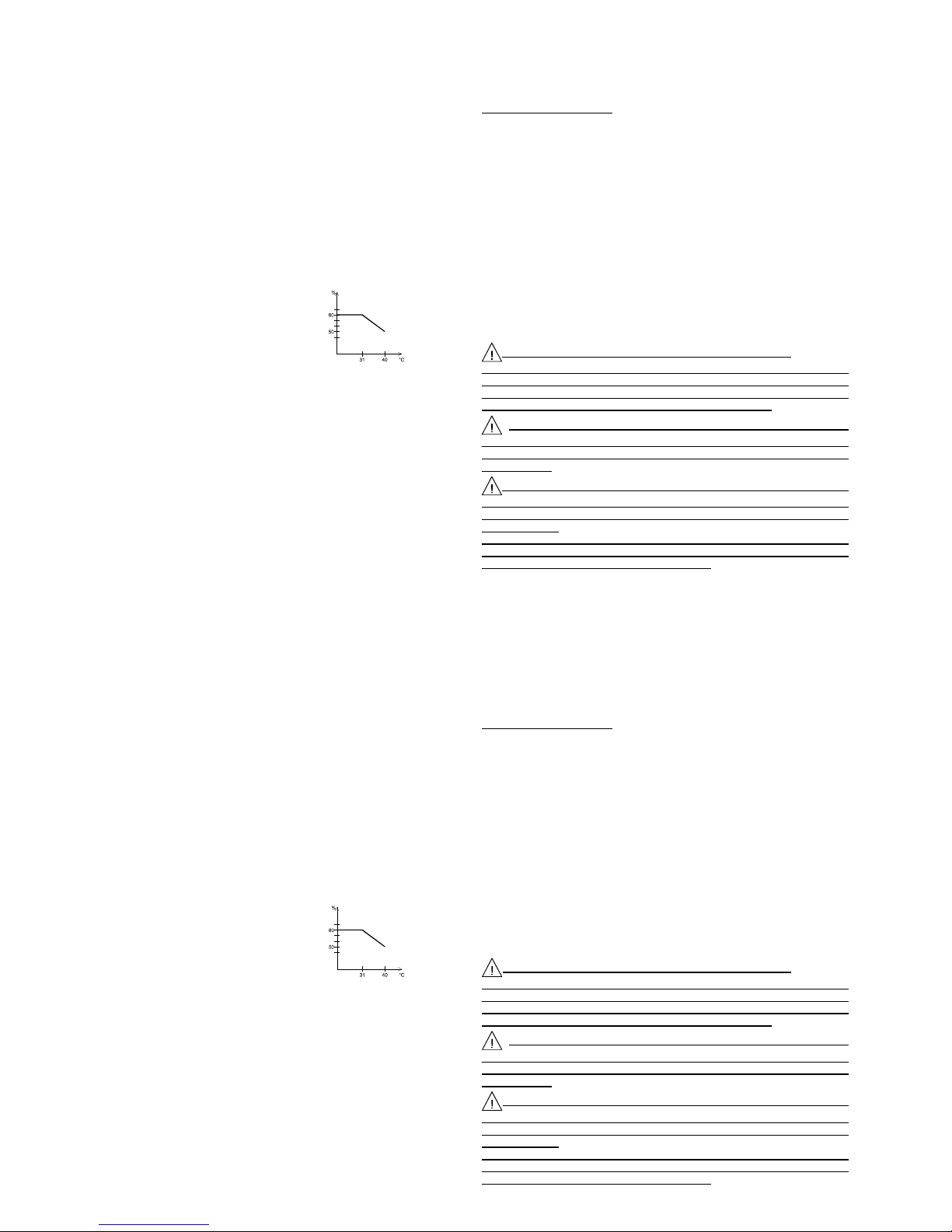
- 16 -
- 16 -
4000 4 195_Rev1 - 07/16 4000 4 195_Rev1 - 07/16
INTENSITA’
I massimo : Alimentazione A : 1 Ampere
Alimentazione B : 3 Ampere a 5.5 V e 1 Ampere a 2 V
Alimentazione C : 0.2 Ampere
Visualizzazione : Lampeggiamento della o delle LED corrispondente alla(e)
alimentazione(i) in sovraccarico.
Visualizzatore : La limitazione d’intensità su un’alimentazione provoca il
lampeggiamento del visualizzatore. Quest’ultimo indica : Ic.A,
Ic.B, Ic.C +1c. secondo la(e) uscita(e) in sovraccarico.
2.3 ALTRE CARATTERISTICHE
Alimentazione : Settore 230V 50/60Hz. Fluttuazione ±10%
Entrata settore : Basamento “EUROPA” CEE 22 con cordone 2 poli +
terra
Consumo massimo : 130VA
Rigidità dielettrica : 2300VAC tra entrata ed uscita
1350VAC tra entrata e telaio
500VDC tra entrata e telaio
Dimensioni : L=215mm, H=96mm, P=200mm
Presentazione : Facciata in policarbonato serigrafata
Rivestimento ambra granulata
Massa : 3.9Kg
Condizioni di utilizzazione : +5°C a +40°C
Condizioni di stoccaggio : -10°C a +50°C
Condizioni di umidità : vedere figura 1
PROTEZIONI
Classe di sicurezza : I
Contro i cortocircuiti : tramite limitazione della corrente
Contro ogni sopra intensità del trasformatore : tramite fusibile al circuito primario
NORME
CEM EN 55011 gruppo 1 classe B
EN 50082-1 Criterio d’attitudine A
SICUREZZA EN 61010-1
Categoria di sovratensione II e grado di inquinamento 2
2.4 COMPOSIZIONE DELL’INSIEME
Il vostro alimentatore AL991s vi è consegnato con il suo cordone settore scheda
“EUROPA”, 2 poli+terra e il suo manuale di istruzioni.
Fig. 1
umidità relativa
massima
3 ISTRUZIONI PRELIMINARI
3.1 IMBALLAGGIO
L’alimentatore,duranteiltrasporto,èprotettodaunimballaggiodicartoneperevitare
qualsiasidanneggiamento.
Conservatelo vi potrà essere utile in futuro
Lista del contenuto del collo :
1 manuale di istruzioni 1 sacco di plastica 1 cordone settore
1 alimentatore : AL991s 2 cali di cartone
3.2 MONTAGGIO E MESSA IN FUNZIONE DELL’APPARECCHIO
Per una buona conversione naturale, l’alimentatore deve essere posato sui suoi 4
piedi di gomma e tutte le aperture di aereazione devono essere pienamente
sgomberate. Collegate il cordone settore nella presa “EUROPA” CEE22 situata
dietro l’apparecchio.
4 PREPARAZIONE AL FUNZIONAMENTO
Raccordare l’alimentatore alla rete 230V e mettere sotto tensione con l’interruttore
On/Off.
5 ISTRUZIONI PER L’UTILIZZAZIONE
5.1 PRESCRIZIONI DI SICUREZZA
Nessun intervento è autorizzato all’interno dell’apparecchio
L’apparecchio deve essere utilizzato conformemente alle istruzioni di questo
documento. Poiché la presa del cordone settore e il dispositivo di
selezionamento sono utilizzati, l’apparecchio deve essere raccordato ad una
presa facilmente accessibile che deve comportare una terra.
Poiché questo apparecchio deve essere alimentato tramite un
autotrasformatore a parte per effettuare una riduzione di tensione, garantitevi
che il terminale comune sia raccordato al polo messo alla terra del circuito di
alimentazione.
Tutte le uscite sono fluttuanti rispetto alla terra. La tensione massima di
modo comune ammessa tra la terra e le uscite è di 50V efficace. Una tensione
giudicata pericolosa (> 60Vdc) può essere raggiunta tra un dei terminali di
uscita e la terra.
In questo caso, bisogna assolutamente utilizzare dei cordoni di sicurezza per
il raccordo con le uscite dell’apparecchio. Inoltre, gli apparecchi raccordati non
devono presentare parti conduttrici accessibili.
ITALIANO

- 17 -
- 17 -
4000 4 195_Rev1 - 07/16 4000 4 195_Rev1 - 07/16
5.2 ORGANI DI COMANDO
5.2.1 Descrizione della parte posteriore
A: PRESA COLLEGAMENTO SERIE RS232
B: BASAMENTO SETTORE
C: PORTA FUSIBILI con FUSIBILE T1.6A
Il fusibile (5 x 20mm T1.6A ) deve essere sostituito da un fusibile di stesso tipo
e di stesse caratteristiche.
5.2.2 Vista d’insieme della facciata avanti
(1) INTERRUTTORE ON/OFF. Posizione on, l’alimentatore è sotto tensione.
Posizione off, l’alimentatore è spento.
(2) PRESE DI USCITA A. Esse forniscono due tensioni simmetriche regolabili da 0
a±15Vconunacorrentedi1A rispetto al terminale COM (4) o da 0 a +30V rispetto
al terminale –15V.
(3) TESTIMONE DI SELEZIONE USCITA A. Il testimone illuminato indica che
l’uscita A è selezionata per la regolazione e la visualizzazione del suo valore sul
visualizzatore (10). Indica anche quando lampeggia che questa uscita è in
sovraccarico.
(4) PRESA COMUNE. Terminale di referenza comune a tutte le uscite.
(5) PRESA DI USCITA B. Fornisce una tensione regolabile di +2V a +5.5V con una
corrente massima compresa tra 1A e 3A.
(6) TESTIMONE SELEZIONE USCITA B. Il testimone illuminato indica che l’uscita
B è selezionata per la regolazione e la visualizzazione del suo valore sul
visualizzatore (10). Indica anche quando lampeggia che questa uscita è in
sovraccarico.
(7) PRESA DI USCITA C. Fornisce una tensione regolabile di -15V a +15V con una
corrente massima di 0.2A.
(8) TESTIMONE SELEZIONE USCITA C. Il testimone illuminato indica che l’uscita
B è selezionata per la regolazione e la visualizzazione del suo valore sul
visualizzatore (10). Indica anche quando lampeggia che questa uscita è in
sovraccarico.
(9) PRESA DI TERRA FUNZIONALE DI SICUREZZA. Permette di referenziare il
vostro montaggio alla terra. Questa presa è direttamente collegata alla terra
tramite il telaio.
C
AB
(10) SELEZIONE DELLE USCITE. Permette la scelta dell’uscita da visualizzare.
Un’ implosione sul tasto scala di un’uscita nel senso A – B – C – A ….
(11) VISUALIZZATORE. Visualizza il valore dell’uscita selezionata da (9). Indica
anche se le uscite sono in sovraccarico.
(12) REGOLAZIONE DI TENSIONE +0.1V. Un’impulsione sul tasto aumenta la
tensione dell’uscita selezionata di 0.1V.
(13) REGOLAZIONE DI TENSIONE -0.1V. Un’impulsione sul tasto diminuisce la
tensione dell’uscita selezionata di 0.1V.
(14) REGOLAZIONE DI TENSIONE +0.1V. Un’impulsione sul tasto aumenta la
tensione dell’uscita selezionata di 0.1V
(15) REGOLAZIONE DI TENSIONE -0.1V. Un’impulsione sul tasto diminuisce la
tensione dell’uscita selezionata di 0.1V.
5.3 FUNZIONAMENTO
- Con la messa sotto tensione, l’alimentatore si posiziona sull’uscita che era stata
selezionata nell’ultima utilizzazione. Tutte le tensioni regolate sono memorizzate
automaticamente. Quindi in caso di arresto improvviso o di taglio settore le
regolazioni sono conservate con la rimessa sotto tensione.
- Selezionare l’uscita da regolare con il tasto (10) e i testimoni (3), (6) e (8).
- Regolare la tensione con i tasti (12) a (15).
- Collegare la carica tra il terminale COM e quella dell’uscita regolata.
- Ripetere l’operazione per le altre uscite.
Tutteleuscitesono disponibili simultaneamente. Potete regolare un’uscita mentre
le altre sono in funzione.
Per disporre di un’alimentazione regolabile da 0 a +30V, bisogna collegarsi
tra le prese –15V e +15V. In questa configurazione, non potete più utilizzare le
due altre alimentazioni sullo stesso montaggio, poiché la referenza non è più
la stessa. Il valore sul visualizzatore e la regolazione sono da moltiplicarsi per
due.
COMUSCITA A USCITA B USCITA C
0 à +15V
0 à -15V
+2V à +5.5V
-15V à +15V
0 à +30V
ITALIANO
5.2 ORGANI DI COMANDO
5.2.1 Descrizione della parte posteriore
A: PRESA COLLEGAMENTO SERIE RS232
B: BASAMENTO SETTORE
C: PORTA FUSIBILI con FUSIBILE T1.6A
Il fusibile (5 x 20mm T1.6A ) deve essere sostituito da un fusibile di stesso tipo
e di stesse caratteristiche.
5.2.2 Vista d’insieme della facciata avanti
(1) INTERRUTTORE ON/OFF. Posizione on, l’alimentatore è sotto tensione.
Posizione off, l’alimentatore è spento.
(2) PRESE DI USCITA A. Esse forniscono due tensioni simmetriche regolabili da 0
a±15Vconunacorrentedi1A rispetto al terminale COM (4) o da 0 a +30V rispetto
al terminale –15V.
(3) TESTIMONE DI SELEZIONE USCITA A. Il testimone illuminato indica che
l’uscita A è selezionata per la regolazione e la visualizzazione del suo valore sul
visualizzatore (10). Indica anche quando lampeggia che questa uscita è in
sovraccarico.
(4) PRESA COMUNE. Terminale di referenza comune a tutte le uscite.
(5) PRESA DI USCITA B. Fornisce una tensione regolabile di +2V a +5.5V con una
corrente massima compresa tra 1A e 3A.
(6) TESTIMONE SELEZIONE USCITA B. Il testimone illuminato indica che l’uscita
B è selezionata per la regolazione e la visualizzazione del suo valore sul
visualizzatore (10). Indica anche quando lampeggia che questa uscita è in
sovraccarico.
(7) PRESA DI USCITA C. Fornisce una tensione regolabile di -15V a +15V con una
corrente massima di 0.2A.
(8) TESTIMONE SELEZIONE USCITA C. Il testimone illuminato indica che l’uscita
B è selezionata per la regolazione e la visualizzazione del suo valore sul
visualizzatore (10). Indica anche quando lampeggia che questa uscita è in
sovraccarico.
(9) PRESA DI TERRA FUNZIONALE DI SICUREZZA. Permette di referenziare il
vostro montaggio alla terra. Questa presa è direttamente collegata alla terra
tramite il telaio.
C
AB
(10) SELEZIONE DELLE USCITE. Permette la scelta dell’uscita da visualizzare.
Un’ implosione sul tasto scala di un’uscita nel senso A – B – C – A ….
(11) VISUALIZZATORE. Visualizza il valore dell’uscita selezionata da (9). Indica
anche se le uscite sono in sovraccarico.
(12) REGOLAZIONE DI TENSIONE +0.1V. Un’impulsione sul tasto aumenta la
tensione dell’uscita selezionata di 0.1V.
(13) REGOLAZIONE DI TENSIONE -0.1V. Un’impulsione sul tasto diminuisce la
tensione dell’uscita selezionata di 0.1V.
(14) REGOLAZIONE DI TENSIONE +0.1V. Un’impulsione sul tasto aumenta la
tensione dell’uscita selezionata di 0.1V
(15) REGOLAZIONE DI TENSIONE -0.1V. Un’impulsione sul tasto diminuisce la
tensione dell’uscita selezionata di 0.1V.
5.3 FUNZIONAMENTO
- Con la messa sotto tensione, l’alimentatore si posiziona sull’uscita che era stata
selezionata nell’ultima utilizzazione. Tutte le tensioni regolate sono memorizzate
automaticamente. Quindi in caso di arresto improvviso o di taglio settore le
regolazioni sono conservate con la rimessa sotto tensione.
- Selezionare l’uscita da regolare con il tasto (10) e i testimoni (3), (6) e (8).
- Regolare la tensione con i tasti (12) a (15).
- Collegare la carica tra il terminale COM e quella dell’uscita regolata.
- Ripetere l’operazione per le altre uscite.
Tutteleuscitesono disponibili simultaneamente. Potete regolare un’uscita mentre
le altre sono in funzione.
Per disporre di un’alimentazione regolabile da 0 a +30V, bisogna collegarsi
tra le prese –15V e +15V. In questa configurazione, non potete più utilizzare le
due altre alimentazioni sullo stesso montaggio, poiché la referenza non è più
la stessa. Il valore sul visualizzatore e la regolazione sono da moltiplicarsi per
due.
ITALIANO
COMUSCITA A USCITA B USCITA C
0 à +15V
0 à -15V
+2V à +5.5V
-15V à +15V
0 à +30V

- 18 -
- 18 -
4000 4 195_Rev1 - 07/16 4000 4 195_Rev1 - 07/16
Incasodi sovraccarico, il testimone della (e) uscita(e) e ilvisualizzatorelampeggiano.
Quest’ultimo visualizza Ic.A, Ic.B, Ic.C o Ic. A seconda dell’uscita(e) in sovraccarico
anche se l’uscita in sovraccarico non è quella selezionata.
5.3.1 Precauzioni
Regolare sempre l’alimentatore prima di applicare la carica. Collegare la carica con
i cordoni isolati di diametro sufficiente. Sconnettere la carica prima dell’arresto
dell’alimentazione. Stoccare l’apparecchio al riparo dalla polvere.
Ogni interruzione delconduttore di protezione,all’esterno dell’apparecchio,
o ogni sconnessione del terminale di terra rischia di rendere l’apparecchio
pericoloso. L’interruzione intenzionale è vietata.
5.4 APPLICAZIONI
Il vostro alimentatore, grazie al suo concepimento, risponde alla maggior parte dei
vostri bisogni. Con l’uscita A, potete alimentare tutti i montaggi che necessitano due
tensioni simmetriche come i circuiti ad amplificatore operazionale o i componenti di
conversione numerici – analogico (e inversamente) che sono sempre più utilizzati.
Inconfigurazione30V,disponetediun’alimentazioneuniversale.Inquestocaso,non
dimenticatecheilvostromontaggioèalimentato in rapporto ai terminali –15V e +15v.
Non potrete più utilizzare le alimentazioni B e C sullo stesso montaggio, poiché non
avranno la stessa referenza. L’uscita B risponde alla domanda dei componenti della
nuovagenerazione tipo microprocessore o logicaprogrammabile.Questicomponenti
si alimentano sotto tensione sempre più deboli con delle correnti a volte elevate. I
comandi digitali apportano un confronto per risolvere le tensioni di 3.3V o 2.7V per
esempio. Essa potrà anche alimentare più generalmente, tutti i componenti di tipo
TTL. Per concludere l’uscita C permette di disporre di una tensione negativa o
positiva molto utile per caratterizzare dei componenti come diodo o transistor per
esempio.Le alimentazioni A+B+C vi permettono dunquedi alimentare direttamente
delle carte miste (analogica/digitale), o delle tensioni come +12V, -12V, +5V e –5V
sono spesso richieste.
6. PILOTAGGIO VIA COMPUTER
Potetepilotare il vostro alimentatore graziealsoftwareLG991s (software da scaricare
sul nostro sito web: elc.fr) e il collegamento RS232 situato dietro l’apparecchio. Per
ilcollegamentobisognamunirsidi un cavo NULL-MODEM blindato di una lunghezza
massima di 15 metri. L’attacco del connettore si trova nella parte posteriore
dell’apparecchio.Dopoavereffettuatoicollegamenti, installate il software seguendo
le istruzioni. Mettere l’alimentatore sotto tensione e attivare il software. Potere allora
comandare il vostro alimentatore con il vostro computer e creare delle sequenze
automatizzate.
Per conoscere il software e la definizione dei codici di comando riferitevi all’aiuto in
linea.
7 MANUTENZIONE
Nessuna manutenzione particolare è da effettuare in questo apparecchio.
Evitate la polvere, l’umidità, i colpi, il vostro apparecchio ve ne sarà grato.
Per la pulizia, utilizzare un panno soffice per la polvere.
Se il visualizzatore non si accende alla messa in tensione, verificare :
- Se l’interruttore on/off è connesso
- La presenza della tensione settore
- Il raccordo alla rete
- Il fusibile di protezione (5x20 T1.6A)
8 SERVIZIO DOPO VENDITA
Il servizio dopo vendita è assicurato dalla società elc.
Ilperiodo di garanziaèdidue annosV pezzi emanod’opera.Non sono tuttaviagarantiti
iguastiodifetticausatidaunacattivautilizzazionedell’apparecchio(tensione settore
non conforme, choc …) o che sono stati riparati da terzi o dalle officine non
autorizzate dai nostri agenti.
9 DICHIARAZIONE DI CONFORMITA UE
Fabbricante : elc
Indirizzo : 59, avenue des Romains 74000 Annecy France
Dichiara che questo prodotto
Nome : Alimentatore stabilizzato
Numero : AL 991s
è conforme alle requisiti delle direttive: Bassa Tensione 2014/35 / UE,
Compatibilità elettromagnetica 2014/30 / EU e RoHS 2011/65 / UE.
Le seguenti norme sono state applicate:
Sicurezza: EN 61010-1: 2010
EMC: EN 61326-1: 2013
Annecy il 2016/07/06 Henry Curri, direttore
ITALIANO
Incasodi sovraccarico, il testimone della (e) uscita(e) e ilvisualizzatorelampeggiano.
Quest’ultimo visualizza Ic.A, Ic.B, Ic.C o Ic. A seconda dell’uscita(e) in sovraccarico
anche se l’uscita in sovraccarico non è quella selezionata.
5.3.1 Precauzioni
Regolare sempre l’alimentatore prima di applicare la carica. Collegare la carica con
i cordoni isolati di diametro sufficiente. Sconnettere la carica prima dell’arresto
dell’alimentazione. Stoccare l’apparecchio al riparo dalla polvere.
Ogni interruzione delconduttore di protezione,all’esterno dell’apparecchio,
o ogni sconnessione del terminale di terra rischia di rendere l’apparecchio
pericoloso. L’interruzione intenzionale è vietata.
5.4 APPLICAZIONI
Il vostro alimentatore, grazie al suo concepimento, risponde alla maggior parte dei
vostri bisogni. Con l’uscita A, potete alimentare tutti i montaggi che necessitano due
tensioni simmetriche come i circuiti ad amplificatore operazionale o i componenti di
conversione numerici – analogico (e inversamente) che sono sempre più utilizzati.
Inconfigurazione30V,disponetediun’alimentazioneuniversale.Inquestocaso,non
dimenticatecheilvostromontaggioèalimentato in rapporto ai terminali –15V e +15v.
Non potrete più utilizzare le alimentazioni B e C sullo stesso montaggio, poiché non
avranno la stessa referenza. L’uscita B risponde alla domanda dei componenti della
nuovagenerazione tipo microprocessore o logicaprogrammabile.Questicomponenti
si alimentano sotto tensione sempre più deboli con delle correnti a volte elevate. I
comandi digitali apportano un confronto per risolvere le tensioni di 3.3V o 2.7V per
esempio. Essa potrà anche alimentare più generalmente, tutti i componenti di tipo
TTL. Per concludere l’uscita C permette di disporre di una tensione negativa o
positiva molto utile per caratterizzare dei componenti come diodo o transistor per
esempio.Le alimentazioni A+B+C vi permettono dunquedi alimentare direttamente
delle carte miste (analogica/digitale), o delle tensioni come +12V, -12V, +5V e –5V
sono spesso richieste.
6. PILOTAGGIO VIA COMPUTER
Potetepilotare il vostro alimentatore graziealsoftwareLG991s (software da scaricare
sul nostro sito web: elc.fr) e il collegamento RS232 situato dietro l’apparecchio. Per
ilcollegamentobisognamunirsidi un cavo NULL-MODEM blindato di una lunghezza
massima di 15 metri. L’attacco del connettore si trova nella parte posteriore
dell’apparecchio.Dopoavereffettuatoicollegamenti, installate il software seguendo
le istruzioni. Mettere l’alimentatore sotto tensione e attivare il software. Potere allora
comandare il vostro alimentatore con il vostro computer e creare delle sequenze
automatizzate.
Per conoscere il software e la definizione dei codici di comando riferitevi all’aiuto in
linea.
7 MANUTENZIONE
Nessuna manutenzione particolare è da effettuare in questo apparecchio.
Evitate la polvere, l’umidità, i colpi, il vostro apparecchio ve ne sarà grato.
Per la pulizia, utilizzare un panno soffice per la polvere.
Se il visualizzatore non si accende alla messa in tensione, verificare :
- Se l’interruttore on/off è connesso
- La presenza della tensione settore
- Il raccordo alla rete
- Il fusibile di protezione (5x20 T1.6A)
8 SERVIZIO DOPO VENDITA
Il servizio dopo vendita è assicurato dalla società elc.
Ilperiododigaranziaèdidueannospezziemanod’opera.Non sono tuttavia garantiti
iguastiodifetticausatidaunacattivautilizzazionedell’apparecchio(tensione settore
non conforme, choc …) o che sono stati riparati da terzi o dalle officine non
autorizzate dai nostri agenti.
9 DICHIARAZIONE DI CONFORMITA UE
Fabbricante : elc
Indirizzo : 59, avenue des Romains 74000 Annecy France
Dichiara che questo prodotto
Nome : Alimentatore stabilizzato
Numero : AL 991s
è conforme alle requisiti delle direttive: Bassa Tensione 2014/35 / UE,
Compatibilità elettromagnetica 2014/30 / EU e RoHS 2011/65 / UE.
Le seguenti norme sono state applicate:
Sicurezza: EN 61010-1: 2010
EMC: EN 61326-1: 2013
Annecy il 2016/07/06 Henry Curri, direttore
ITALIANO

- 19 -
- 19 -
4000 4 195_Rev1 - 07/16 4000 4 195_Rev1 - 07/16
SMALTIMENTO DEI RIFIUTI DA PARTE DEGLI UTENTI NEL
FAMIGLIENELL’UNIONEEUROPEA.
Questo simbolo sul prodotto o sulla sua confezione indica che
il prodotto non deve essere scartata con gli altri rifiuti domestici.
E ‘vostra responsabilità per sbarazzarsi del vostro rifiuti,
fornendo un punto di raccolta designato per il riciclo di
apparecchiature elettriche ed elettroniche.
La raccolta e il riciclaggio dei rifiuti separati tuo al momento della
cessionecontribuiràaconservarelerisorse naturali e riciclaggio
di garantire l’ambiente e la salute umana.
Per maggiori informazioni sul centro di riciclaggio più vicino,
contattare il più vicino municipio, lo smaltimento dei rifiuti o il
negozio dove avete acquistato il prodotto.
ELIMINATION OF MANUFACTURING WASTES BY THE PRIVATE
USERSIN THE EU
This symbol written in the product or in its packaging indicates
thatthisproductmustnot be throw in the garbage with your other
waste.
Its your responsability to rid of your manufacturing wastes
bringing it to a specialized sorting office for the recycling of
electrical and electronic instruments.
Collectionandrecycling separated of your wastes will contribute
to preserve natural resources and guarantee a recycling
respectful of the Environment and human health.
Forfurtherinformationconcerningtherecycling center near your place of residence,
contact your town hall, the elimination service of garbage heap or the store where
you bought the instrument.
BESEITIGUNGDERABFÄLLE DURCH DEN BENUTZER IN DIE
PRIVATENHAUSHALTE IN DER EUROPÄISCHENUNION.
Dieses Symbol auf dem Produkt oder der Verpackung weist
darauf hin, dass dieses Produkt darf nicht mit deinen anderen
geworfenHausmüll.
Es ist Ihre Verantwortung befreien Sie Ihre Abfälle in die etwas
zueinerSammelstellebenannt,umdas Recyclingvonelektrischen
und elektronischen Geräten.
Diegetrennte Sammlung und Wiederverwertung Ihrer Abfällebei
der Entsorgung zur Erhaltung der natürlichen Ressourcen und
GewährleistungeinesRecyclingderUmwelt-unddermenschlichen
Gesundheit.
WeitereInformationenüberdasRecyclingderinIhrer Nähe, bei der Stadtverwaltung
die nächste, der zur Entsorgung von Hausmüll oder dem Geschäft, in dem Sie das
Produkt gekauft haben.
ELC,OFFREÀSESCLIENTSDESSOLUTIONS DE RECYCLAGE
Afin de remplir ses obligations, elc adhère à Récylum et
finance la filière de collecte et de recyclage agréée pour les
déchets électriques professionnels (DEEE Pro). Cet
engagement volontaire de elc, permet à ses clients de
bénéficier de solutions simples et gratuites pour assurer le
recyclage de leurs alimentations électriques, module de
secours,générateurs de fonctionset sondesoscilloscopes.
Ainsi, les clients de notre société peuvent se défaire
gratuitementdeleursmatérielsEEEprofessionnels(désignés
précédemment) usagés. Ils obtiennent, certificat à la clé,
l'assurance d'un traitement rigoureux conforme à la règlementation. Il leur suffit de
faire appel à Récylum qui leur indiquera la solution de collecte la plus adaptée à leur
besoin.
Pour connaître toutes les solutions de collecte : www.recylum.com

Satisfied with your acquisition ?
So, you will also be satisfied with :
PROTECTED functions generators
OEM power supplies
and accessories
For more details, go to : www.elc.fr
DR08 DR 07 DR06 DR05 DR04 DL 07 DC 05
resistance box inductance box capacitance box
GF467F :
0,01Hz to 5MHz
RS 232
GF467AF amplified:
0,01Hz to 5MHz
RS 232
ª
ªROBUST decade boxes
ªª
GF266 :
11µHz to12 MHz
RS 232
GF266 :
11µHz to12 MHz
RS 232
Table of contents
Languages:
Other ELC Power Supply manuals


Popular Power Supply manuals by other brands

Videx
Videx 520MR Installation instruction

Poppstar
Poppstar 1008821 Instructions for use

TDK-Lambda
TDK-Lambda LZS-A1000-3 Installation, operation and maintenance manual

TDK-Lambda
TDK-Lambda 500A instruction manual

Calira
Calira EVS 17/07-DS/IU operating instructions

Monacor
Monacor PS-12CCD instruction manual


