TEXIO PU6-200 User manual

1500W SERIES DC POWER SUPPLY
PU SERIES
PU6-200 6V/200A PU8-180 8V/180A
PU12.5-120 12.5V/120A PU20-76 20V/76A
PU30-50 3V/50A PU40-38 40V/38A
PU60-25 60V/25A PU80-19 80V/19A
PU100-15 100V/15A PU150-10 150V/10A
PU300-5 300V/5A PU600-2.6 600V/2.6A
INSTRUCTION MANUAL
© PRINTED IN JAPAN B65-0168-28


CONTENTS
WARRANTY..........................................................................................................................................Ⅰ
SAFETY INSTRUCTIONS..................................................................................................................................................................... Ⅱ
1. GENERAL INFORMATION .................................................................................................................. 1
1.1. USER MANUAL CONTENT.................................................................................................................................................1
1.2. INTRODUCTION......................................................................................................................................................................1
1.2.1 General description ...............................................................................................................................................................1
1.2.2 Models covered by this manual ........................................................................................................................................1
1.2.3 Features and options............................................................................................................................................................2
1.2.4 Multiple output power system...........................................................................................................................................2
1.2.5 Control via the serial communication port...................................................................................................................2
1.2.6 Analog voltage programming and monitoring...............................................................................................................2
1.2.7 Parallel operation....................................................................................................................................................................3
1.2.8 Output connections...............................................................................................................................................................3
1.2.9 Cooling and mechanical construction ............................................................................................................................3
1.3. ACCESSORIES ........................................................................................................................................................................3
1.3.1 General.......................................................................................................................................................................................3
1.3.2 Serial link cable.......................................................................................................................................................................3
1.3.3 Misc. hardware.........................................................................................................................................................................3
1.3.4 AC cables..................................................................................................................................................................................4
1.3.5 Serial Port Cables..................................................................................................................................................................4
2. SPECIFICATIONS .............................................................................................................................. 5
2.1. OUTPUT RATING ...................................................................................................................................................................5
2.2. INPUT CHARACTERISTICS ...............................................................................................................................................5
2.3. CONSTANT VOLTAGE MODE ..........................................................................................................................................5
2.4. CONSTANT CURRENT MODE ..........................................................................................................................................5
2.5. ANALOG PROGRAMMING AND MONITORING .........................................................................................................6
2.6. OUTPUT RATING AND READBACK (RS232/485,Optional IEEE Interface) (At the time of 23℃±5℃).......................6
2.7. PROTECTIVE FUNCTIONS ................................................................................................................................................6
2.8. FRONT PANEL.........................................................................................................................................................................6
2.9. ENVIRONMENTAL CONDITIONS.....................................................................................................................................7
2.10. MECHANICAL...............................................................................................................................................................................7
2.11. SAFETY/EMC ..............................................................................................................................................................................7
2.12. SUPPLEMENTAL CHARACTERISTICS .........................................................................................................................7
3. INSTALLATION ................................................................................................................................. 9
3.1. GENERAL ...................................................................................................................................................................................9
3.2. PREPARATION FOR USE ...................................................................................................................................................9
3.3. INITIAL INSPECTION ............................................................................................................................................................9
3.4. RACK MOUNTING ............................................................................................................................................................... 10
3.5. LOCATION, MOUNTING AND COOLING................................................................................................................... 10
3.6. AC SOURCE REQUIREMENTS ...................................................................................................................................... 10

3.7. AC INPUT POWER CONNECTION ............................................................................................................................... 11
3.7.1 AC Input Connector........................................................................................................................................................... 11
3.7.2 AC Input Cord....................................................................................................................................................................... 11
3.7.3 AC Input Wire Connection, 1500W models................................................................................................................ 11
3.7.4 Time to Heat Beforehand................................................................................................................................................. 12
3.8. TURN-ON CHECKOUT PROCEDURE......................................................................................................................... 12
3.8.1 General.................................................................................................................................................................................... 12
3.8.2 Prior to Operation............................................................................................................................................................... 13
3.8.3 Constant Voltage Check .................................................................................................................................................. 13
3.8.4 Constant Current Check.................................................................................................................................................. 13
3.8.5 OVP Check............................................................................................................................................................................ 14
3.8.6 UVL Check............................................................................................................................................................................. 14
3.8.7 Foldback Check.................................................................................................................................................................... 14
3.8.8 Address Setting ................................................................................................................................................................... 15
3.8.9 Baud Rate Setting............................................................................................................................................................... 15
3.9. CONNECTING THE LOAD ............................................................................................................................................... 15
3.9.1 Load Wiring ............................................................................................................................................................................ 15
3.9.2 Current Carrying Capacity............................................................................................................................................... 15
3.9.3 Wire termination................................................................................................................................................................... 16
3.9.4 Noise and Impedance Effects......................................................................................................................................... 17
3.9.5 Inductive loads ..................................................................................................................................................................... 17
3.9.6 Making the load connections .......................................................................................................................................... 17
3.9.7 Connecting single loads, local sensing (default)...................................................................................................... 20
3.9.8 Connecting single loads, remote sensing................................................................................................................... 20
3.9.9 Connecting multiple loads, radial distribution method.......................................................................................... 21
3.9.10 Multiple load connection with distribution terminals .......................................................................................... 21
3.9.11 Grounding outputs............................................................................................................................................................ 22
3.10. LOCAL AND REMOTE SENSING ...................................................................................................................................... 22
3.10.1 Sense wiring........................................................................................................................................................................ 22
3.10.2 Local sensing...................................................................................................................................................................... 23
3.10.3 Remote sensing ................................................................................................................................................................. 23
3.10.4 J2 sense connector technical information ............................................................................................................. 24
4. FRONT AND REAR PANEL CONTROLS AND CONNECTORS ........................................................... 25
4.1. INTRODUCTION................................................................................................................................................................... 25
4.2. FRONT PANEL CONTROLS AND INDICATORS.................................................................................................... 25
4.3. REAR PANEL......................................................................................................................................................................... 27
4.4. REAR PANEL SW1 SETUP SWITCH............................................................................................................................ 28
4.4.1 SW1 position functions ..................................................................................................................................................... 29
4.4.2 Resetting the SW1 switch................................................................................................................................................ 29
4.5. REAR PANEL J1 PROGRAMMING AND MONITORING CONNECTOR......................................................... 30

4.5.1 Making J1 connections ..................................................................................................................................................... 30
5. LOCAL OPERATION ........................................................................................................................ 32
5.1. INTRODUCTION................................................................................................................................................................... 32
5.2. STANDARD OPERATION................................................................................................................................................. 32
5.2.1 Constant Voltage Mode.................................................................................................................................................... 32
5.2.2 Constant Current Operation........................................................................................................................................... 33
5.2.3 Automatic Crossover......................................................................................................................................................... 33
5.3. OVER VOLTAGE PROTECTION (OVP)...................................................................................................................... 33
5.3.1 Setting the OVP level........................................................................................................................................................ 33
5.3.2 Activated OVP protection indications........................................................................................................................ 34
5.3.3 Resetting the OVP circuit ............................................................................................................................................... 34
5.4. UNDER VOLTAGE LIMIT (UVL)..................................................................................................................................... 34
5.4.1 Setting the UVL level ........................................................................................................................................................ 34
5.5. FOLDBACK PROTECTION .............................................................................................................................................. 34
5.5.1 Setting the Foldback protection.................................................................................................................................... 35
5.5.2 Resetting activated Foldback protection................................................................................................................... 35
5.6. OUTPUT ON/OFF CONTROL........................................................................................................................................ 35
5.7. OUTPUT SHUT-OFF (SO) CONTROL VIA REAR PANEL J1 CONNECTOR ............................................. 35
5.8. ENABLE/DISABLE CONTROL VIA REAR PANEL J1 CONNECTOR ............................................................ 36
5.9. CV/CC SIGNAL.................................................................................................................................................................... 36
5.10. PS_OK SIGNAL ......................................................................................................................................................................... 37
5.11. SAFE START AND AUTO-RESTART MODES........................................................................................................ 37
5.11.1Automatic start mode....................................................................................................................................................... 37
5.11.2 Safe start mode................................................................................................................................................................. 37
5.12. OVER TEMPERATURE PROTECTION (OTP).......................................................................................................... 37
5.13. LAST SETTING MEMORY ................................................................................................................................................ 38
5.14. SERIES OPERATION.......................................................................................................................................................... 38
5.14.1 Series connection for increased output voltage .................................................................................................. 38
5.14.2 Series connection for positive and negative output voltage........................................................................... 40
5.15. PARALLEL OPERATION................................................................................................................................................... 41
5.16. DAISY-CHAIN CONNECTION ........................................................................................................................................ 42
5.17. FRONT PANEL LOCKING ................................................................................................................................................ 43
5.17.1 Unlocked front panel ....................................................................................................................................................... 43
5.17.2 Locked front panel ........................................................................................................................................................... 43
6. REMOTE ANALOG PROGRAMMING................................................................................................. 44
6.1. INTRODUCTION................................................................................................................................................................... 44
6.2. LOCAL /REMOTE ANALOG CONTROL .................................................................................................................... 44
6.3. LOCAL/REMOTE ANALOG INDICATION.................................................................................................................. 44
6.4. REMOTE VOLTAGE PROGRAMMING OF OUTPUT VOLTAGE AND CURRENT LIMIT........................ 45

6.5. RESISTIVE PROGRAMMING OF OUTPUT VOLTAGE AND CURRENT LIMIT .......................................... 46
6.6. REMOTE MONITORING OF OUTPUT VOLTAGE AND CURRENT ................................................................. 47
7. RS232 & RS485 REMOTE CONTROL................................................................................................ 49
7.1. INTRODUCTION................................................................................................................................................................... 49
7.2. CONFIGURATION................................................................................................................................................................ 49
7.2.1 Default setting...................................................................................................................................................................... 49
7.2.2 Address setting.................................................................................................................................................................... 49
7.2.3 RS232 or RS485 selection............................................................................................................................................... 49
7.2.4 Baud rate setting................................................................................................................................................................. 49
7.2.5 Setting the unit into Remote or Local mode............................................................................................................ 50
7.2.6 RS232/485 port in Local mode ..................................................................................................................................... 50
7.2.7 Front panel in Remote mode .......................................................................................................................................... 50
7.3. REAR PANEL RS232/485 CONNECTOR................................................................................................................... 51
7.4. CONNECTING POWER SUPPLIES TO RS232 OR RS485 BUS ....................................................................... 51
7.4.1 Single power supply............................................................................................................................................................ 51
7.4.2 Multi power supply connection to RS232 or RS485 bus..................................................................................... 52
7.4.3 Termination............................................................................................................................................................................ 53
7.5. COMMUNICATION INTERFACE PROTOCOL.......................................................................................................... 53
7.5.1 Data format............................................................................................................................................................................ 53
7.5.2 Addressing.............................................................................................................................................................................. 53
7.5.3 End of Message.................................................................................................................................................................... 53
7.5.4 Checksum............................................................................................................................................................................... 53
7.5.5 Acknowledge ......................................................................................................................................................................... 53
7.5.6 Error message....................................................................................................................................................................... 54
7.5.7 Backspace.............................................................................................................................................................................. 54
7.6. ERROR MESSAGES............................................................................................................................................................ 54
7.7. COMMAND SET DESCRIPTION .................................................................................................................................... 55
7.7.1 General guides...................................................................................................................................................................... 55
7.7.2 Command set categories ................................................................................................................................................. 55
7.7.3 Initialization control commands ..................................................................................................................................... 56
7.7.4 ID control commands......................................................................................................................................................... 56
7.7.5 Output control commands............................................................................................................................................... 56
7.7.6 Status control commands................................................................................................................................................ 58
7.8. STATUS, ERROR AND SRQ REGISTERS........................................................................................................................ 59
7.8.1 General.................................................................................................................................................................................... 59
7.8.2 Conditional registers.......................................................................................................................................................... 59
7.8.3 Service Request: Enable and Event Registers ........................................................................................................ 61

8. ISOLATED ANALOG PROGRAMMING OPTION................................................................................. 64
8.1. NTRODUCTION ............................................................................................................................ 64
8.2. SPECIFICATIONS................................................................................................................................................................ 64
8.2.1 0-5V/0-10V option ............................................................................................................................................................ 64
8.2.2 4-20mA option ..................................................................................................................................................................... 64
8.3. ISOLATED PROGRAMMING & MONITORING CONNECTOR............................................................................ 65
8.4. SETUP AND OPERATING INSTRUCTIONS.............................................................................................................. 66
8.4.1 Setting up the power supply for 0-5/0-10V Isolated Programming and Monitoring................................ 66
8.4.2 Setting up the power supply for 4-20mA Isolated Programming and Monitoring...................................... 66
9. MAINTENANCE................................................................................................................................ 67
9.1. INTRODUCTION................................................................................................................................................................... 67
9.2. UNITS UNDER WARRANTY............................................................................................................................................. 67
9.3. PERIODIC MAINTENANCE .............................................................................................................................................. 67
9.4. ADJUSTMENTS AND CALIBRATION.......................................................................................................................... 67
9.5. PARTS REPLACEMENT AND REPAIRS .................................................................................................................... 67
9.6. TROUBLESHOOTING ........................................................................................................................................................ 67
9.7. FUSE RATING ....................................................................................................................................................................... 68


I
LIMITATION OF WARRANTY
The warranty shall not apply to defects resulting from improper or inadequate usage or maintenance by
the buyer, buyer supplied products or interfacing. The warranty shall not apply to defects resulting from
unauthorized modifications or from operation exceeding the environmental specifications of the product or
if the QA seal has been removed or altered by anyone other than TEXIO authorized personnel. TEXIO does
not warrant the buyer’s circuitry or malfunctions of TEXIO products resulting from the buyer’s circuitry.
Furthermore, TEXIO does not warrant any damage occurring as a result of the buyer’s circuitry or the
buyer’s - supplied products.
No other warranty is expressed of implied.
WARRANTY SERVICE
This product must be returned to an authorized TEXIO service facility for repairs or other warranty
service. For products returned to TEXIO for warranty service, the buyer shall prepay shipping charges
toTEXIO and TEXIO shall pay the shipping charges to return the product to the buyer. Refer to section
3.11 for repackaging for shipment.
DISCLAIMER
The information contained in this document is subject to change without notice. TEXIO shall not be liable
for errors contained in this document or for incidental or consequential damages in connection with the
furnishing, performance or use of this material. No part of this document may be photocopied, reproduced
or translated into another language without the prior written consent of TEXIO.
TRADEMARK INFORMATION
Microsoft and Windows are trademarks of Microsoft Corporation.
THE FCC WANTS YOU TO KNOW
This equipment has been tested and found to comply with the limits for a Class A digital device, pursuant
to Part 15 of the FCC rules. These limits are designed to provide reasonable protection against harmful
interference when the equipment is operated in a commercial environment.
This equipment generates, uses and can radiate radio frequency energy and, if not installed and used in
accordance with the instructions, may cause harmful interference to radio communications.
Operation of this equipment in a residential area is likely to cause harmful interference, in which case the
user will be required to correct the interference at his own expense.
FCC WARNING
Modifications not expressly approved by manufacturer could void the user authority to operate the
equipment under FCC Rules.

II
SAFETY INSTRUCTIONS
CAUTION
The following safety precaution must be observed during all phases of operation, service and repair of this
equipment. Failure to comply with the safety precautions or warnings in this document violates safety
standards of design, manufacture and intended use of this equipment and may impair the built-in
protections within.
TEXIO shall not be liable for user’s failure to comply with these requirements.
INSTALLATION CATEGORY
The PU power supply series has been evaluated to INSTALLATION CATEGORY II.
Installation category (over voltage category) II: local level, appliances, portable equipment etc. With smaller
transient over voltage than Installation Category (over voltage category) III.
GROUNDING
This product is a Safety Class 1 instrument. To minimize shock hazard, the instrument chassis must be
connected to an electrical ground. The instrument must be connected to the AC power supply mains
through a three conductor power cable, with the ground wire firmly connected to an electrical ground
(safety ground) at the power outlet.
For instruments designed to be hard-wired to the supply mains, the protective earth terminal must be
connected to the safety electrical ground before another connection is made. Any interruption of the
protective ground conductor, or disconnection of the protective earth terminal will cause a potential shock
hazard that might cause personal injury.
FUSES
Fuses must be changed by authorized TEXIO service personnel only. For continued protection against risk
of fire, replace only with the same type and rating of fuse. Refer to maintenance instructions in chapter 9
for fuses rating.
INPUT RATINGS
Do not use AC supply which exceeds the input voltage and frequency rating of this instrument. The input
voltage and frequency rating of the PU power supply series is: 100-240V, 50/60Hz.
For safety reasons, the mains supply voltage fluctuations should not exceed +/-10% of nominal voltage.
WARNING
OUTPUT TERMINAL GROUNDING
There is a potential shock hazard at the RS232/485 and the IEEE ports when using power supplies
with rated or combined voltage greater than 400V and the Positive Output of the Power Supply is
grounded. Do not connect the Positive Output to ground when using the RS232/485 or IEEE.
III
LIVE CIRCUITS
Operating personnel must not remove the instrument cover. No internal adjustment or component
replacement is allowed by non-TEXIO qualified personnel. Never replace components with power cable
connected. To avoid injuries, always disconnect power, discharge circuits and remove external voltage
source before touching components.
PARTS SUBSTITUTIONS&MODIFICATIONS
Parts substitutions and modifications are allowed by authorized TEXIO service personnel only. For repairs
or modifications, the instrument must be returned to TEXIO service facility.
ENVIRONMENTAL CONDITIONS
The PU power supply series safety approval applies to the following operating conditions:
*Indoor use
*Ambient temperature: 0 C to 50 C
*Maximum relative humidity: 90% (no condensation)
*Altitude: up to 3000m
*Pollution degree 2
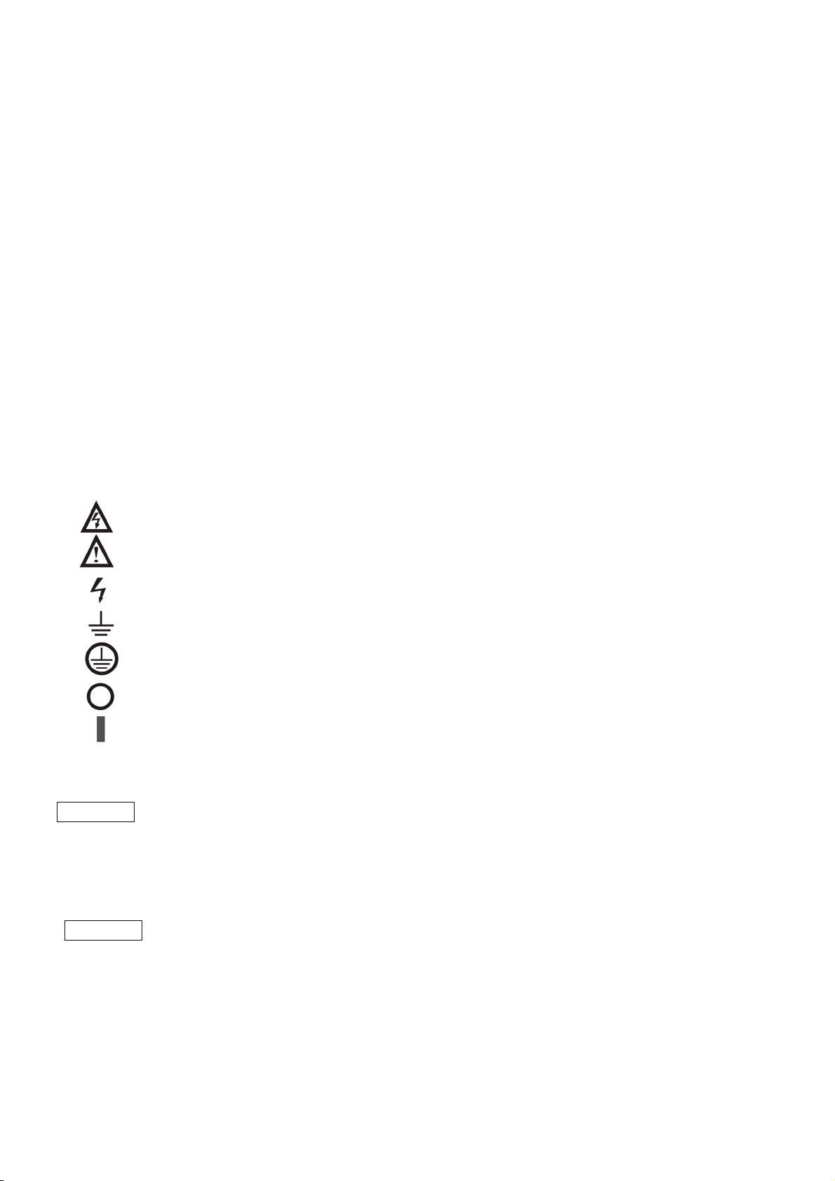
CAUTION Risk of Electrical Shock.
Instruction manual symbol. The instrument will be marked with this symbol when it is
necessary for the user to refer to the instruction manual.
Indicates hazardous voltage.
Indicates ground terminal.
Protective Ground Conductor Terminal
Off (Supply)
On (Supply)
WARNING The WARNING sign denotes a hazard. An attention to a procedure is called.
Not following procedure correctly could result in personal injury.
AWARNING sign should not be skipped and all indicated conditions must be fully understood
and met.
CAUTION The CAUTION sign denotes a hazard. An attention to a procedure is called. Not following
procedure correctly could result in damage to the equipment. Do not proceed beyond a
CAUTION sign until all indicated conditions are fully understood and met.

IV
FCC COMPLIANCE NOTICE:
Note: This equipment has been tested and found to comply with the limits for a Class A digital device,
pursuant to part 15 of the FCC Rules. These limits are designed to provide reasonable protection against
harmful interference when the equipment is operated in a commercial environment. This equipment
generates uses, and can radiate radio frequency energy and, if not installed and used in accordance with
the instruction manual, may cause harmful interference to radio communications. Operation of this
equipment in a residential area is likely to cause harmful interference in which case the user will be
required to correct the interference at his own expense.

1
1. GENERAL INFORMATION
1.1. USER MANUAL CONTENT
This user’s manual contains the operating instructions, installation instructions and specifications of
the PU 1500W power supply series. The instructions refer to the standard power supplies, including
the built-in RS232/485 serial communication. For information related to operation with the optional
IEEE programming, refer to User Manual for Power Supply IEEE programming Interface.
1.2. INTRODUCTION
1.2.1 General description
PU power supplies are wide output range, high performance switching power supplies. The PU series
is power factor corrected and operates from worldwide AC voltage range continuously. Output
voltage and current are continuously displayed and LED indicators show the complete operating
status of the power supply. The Front panel controls allow the user to set the output parameters, the
protection levels (Over-Voltage protection, Under-Voltage limit and Foldback) and preview the
settings. The rear panel includes the necessary connectors to control and monitor the power supply
operation by remote analog signals or by the built-in serial communication (RS232/485). GPIB
programming and Isolated-Analog programming/monitoring are optional.
1.2.2 Models covered by this manual
Table1-1: Models covered by the manual
Model Voltage Current
range (V) range (A)
PU 6-200 0-6 0-200
PU 8-180 0-8 0-180
PU 12.5-120 0-12.5 0-120
PU 20-76 0-20 0-76
PU 30-50 0-30 0-50
PU 40-38 0-40 0-38
PU 60-25 0-60 0-25
PU 80-19 0-80 0-19
PU 100-15 0-100 0-15
PU 150-10 0-150 0-10
PU 300-5 0-300 0-5
PU 600-2.6 0-600 0-2.6

2
1.2.3 Features and options
* Constant Voltage / Constant Current with automatic crossover.
* Active Power Factor correction.
* Universal Input Voltage 85-265Vac, continuous operation.
* Embedded Microprocessor Controller.
* Built in RS232/485 Interface.
* Voltage & Current high resolution adjustment by digital encoders.
* High accuracy programming/readback-16 bit.
* Software Calibration (no internal trimmers / potentiometers).
* Last Setting Memory.
* Independent Remote ON/OFF (opt-isolated) and Remote Enable/Disable.
* Parallel operation (Master/Slave) with Active current sharing.
* Remote sensing to compensate for voltage drop of power leads.
* Cooling fan speed control for low noise and extended fan life.
* Zero stacking- no ventilation holes at the top and bottom surface of the power supply.
* Optional GPIB interface (SCPI compatible).
* Optional Isolated Analog programming/monitoring (0-5V or 0-10V, user selectable and
4-20mA).
1.2.4 Multiple output power system
The PU power supplies series can be configured into a programmable power system of up to 31
units using the built-in RS232/RS485 communication port in the power supply and the RS485
linking cable provided with each power supply.
In a GPIB system, each power supply can be controlled using the optional GPIB controller (factory
installed).
1.2.5 Control via the serial communication port
The following parameters can be programmed via the serial communication port:
1. Output voltage setting.
2. Output current setting.
3. Output voltage measurement.
4. Output current measurement
5. Output on/off control.
6. Foldback protection setting.
7. Over-voltage protection setting and readback.
8. Under-Voltage limit setting and readback.
9. Power-supply start up mode (last setting or safe mode)
1.2.6 Analog voltage programming and monitoring
Analog inputs and outputs are provided at the rear panel for analog control of the power supply. The
output voltage and the current limit can be programmed by analog voltage or by resistor, and can be
monitored by analog voltage. The power supply output can be remotely set to On or Off and analog
signals monitor the proper operation of the power supply and the mode of operation (CV/CC).

3
1.2.7 Parallel operation
PU power supplies of the same output voltage and current rating can be paralleled in master-slave
configuration with automatic current sharing to increase power available.
1.2.8 Output connections
Output connections are made to rear panel bus-bars for models up to 60V and to a 4-terminal wire
clamp connector for models above 60V rated output voltage. Either the positive or negative
terminal may be grounded or the output may be floated. Models up to 60VDC Rated Output shall
not float outputs more than +/- 60VDC above/below chassis ground. Models >60VDC Rated
Output shall not float outputs more than +/-600VDC above/below chassis ground. Contact factory
for assistance with higher float voltage applications.
Local or remote sense may be used. In remote sense, the voltage drop on the load wires should be
minimized. Refer to the specifications for the maximum voltage drop value.
1.2.9 Cooling and mechanical construction
The PU series is cooled by internal fans. At the installation, care must be taken to allow free air flow
into the power supply via the front panel and out of the power supply via the rear panel. The PU
power supplies have a compact and lightweight package which allows easy installation and space
saving in the application equipment.
CAUTION
1.3. ACCESSORIES
1.3.1 General
Accessories are delivered with the power supply or separately upon ordering. The list below shows
the possible accessories and ordering numbers.
1.3.2 Serial link cable
Serial link cable, for linking power supplies by RS485 communication is provided with the power
Supply.
Cable description 0.5m length, shielded, RJ-45 type plugs, 8 contacts.
1.3.3 Misc. hardware
* DB25 plug (AMP, 745211-2)
* Strain relief for AC cord (for 1500W models only)
* Output terminal shield
Observe all torque guidelines within this manual. Over torqueing may
damage unit or accessories. Such damage is not covered under
manufacturers warranty.

4
1.3.4 AC cables
Please prepare AC cable with the following specification for 1500W model.
25A 250V, 12AWG or 10AWG (3 Core Wire)
Outer diameter : 9-11mm
Rated temperature : 60℃ or more
Length : 3m or less
Please use safety approved plug in each country.
1.3.5 Serial Port Cables
Refer to section 7.4

5
2. SPECIFICATIONS
2.1. OUTPUT RATING
MODEL 6-200 8-180 12.5-120 20-76 30-50 40-38 60-25 80-19 100-15 150-10 300-5 600-2.6
1.Rated output voltage(*1) V 6 8 12.5 20 30 40 60 80 100 150 300 600
2.Rated output current 1500w(*2) A 200 180 120 76 50 38 25 19 15 10 5 2.6
3.Rated output power 1500w W 1200 1440 1500 1520 1500 1520 1500 1520 1500 1500 1500 1560
2.2. INPUT CHARACTERISTICS
V 6 8 12.5 20 30 40 60 80 100 150 300 600
1.Input voltage/freq.(*3) - 85~265VAC continuous,47~63Hz,single phase.
2.Input current(at 100/200VAC) A 21/11 for 1500W models.
3.Power Factor - 0.99 @100/200VAC, rated output power.
4.1500W models Efficiency (*4) % 77/79 78/81 82/85 83/86 83/86 84/88 84/88 84/88 84/88 84/88 84/88 84/88
5.Inrysh current at 100/200v A Less than 50A for 1500W models.
2.3. CONSTANT VOLTAGE MODE
V 6 8 12.5 20 30 40 60 80 100 150 300 600
1. Max. Line regulation (*5) - 0.01% of rated output voltage +2mV
2. Max. Load regulation (*6) - 0.01% of rated output voltage +2mV
3.Ripple and noise (p-p,20MHz)
(Following 30 minutes
warm-up).
mV 60 60 60 60 60 60 60 80 80 100 150 300
4.Ripple r.m.s.,5Hz~1MHz
(Following 30 minutes
warm-up).
mV 8 8 8 8 8 8 8 8 8 10 25 60
5.Temperature coefficient ppm/℃ 100ppm/℃ from rated output voltage,following,30 minutes warm-up.
6.Temperature drift - 0.05% of rated Volt over 8hours interval following 30 minutes warm-up. Constant line, load & temp.
7.Rem. sense compensation/wire V 1 1 1 1 1.5 2 3 4 5 5 5 5
8.Up-prog.response time,0-Vomax (*9) m.s 90 120 150 250
m.s 10 50 80 150 250 9.Dow
n
-prog.response time: Full load
No load 500 600 700 900 1000 1100 1200 1400 1700 2400 3000 4800
10.Transient response time m.s
Time for the output voltage to recover within 0.5% of its rated output for a load change 10-90% of rated
output current.
Output set-point:10-100%
Less than 1m.s, for models up to and including 100V. 2m.s, for models above 100.
11.Hold-up time ms More than 200m.s, 100Vac, rated output power.
2.4. CONSTANT CURRENT MODE
V 6 8 12.5 20 30 40 60 80 100 150 300 600
1. Max. Line regulation (*5) - 0.01% of rated output current +2mA
2. Max. Load regulation (*7) - 0.02% of rated output current +5mA
3.Ripple r.m.s 5Hz-1MHz (*8) mA 400 360 240 152 125 95 75 57 45 35 25 12
4.Temperature coefficient ppm/℃ 100ppm/℃ from rated output current, following 30 minutes warm-up.
5.Temperature drift - 0.05% of rated lout over 8hours interval following 30 minutes warm-up. Constant line, load & temp.

6
2.5. ANALOG PROGRAMMING AND MONITORING
1.volt voltage programming -- 0-100%,0-5V/ 0-10V,user select, Accuracy and linearity:±0.5% of rated Volt.
2.Iout voltage programming -- 0-100%,0-5V /0-10V,user select, Accuracy and linearity:±1% of rated Iout.
3.Vout resistor programming -- 0-100%,0-5/0~10kΩfull scale, user select, Accuracy and linearity:±1% of rated Volt.
4.Iout resistor programming -- 0-100%,0-5/0~10kΩfull scale, user select, Accuracy and linearity:±1.5% of rated Iout.
5.ON/OFF control -- By electrical Voltage: 0-0.6V/2-15V, or dry contact, user selectable logic.
6.Output current monitor -- 0-5V or 0~10V、user selectable.Accuracy:1%.
7.Output voltage monitor -- 0-5V or 0~10V、user selectable.Accuracy:1%.
8.Power supply OK signal -- 4-5V OK, 0V-Fail. 500ohm series resistance.
9.Parallel operation (*10) -- Possible, up to 4 units in master/slave mode with single wire current balance connection.
10.Series operation -- Possible (with external diodes), up to 2 units.
11.CV/CC indicator -- CV: TTL high (4~5V),source current:10mA, CC: TTL low (0~0.6V),sink currenct:10mA.
12.ON/OFF control -- Dry contact. Open: off, Short: on. Max. Voltage at ON/OFF in: 6V.
13.Local/Remote analog Control -- By electrical signal or Open/Short: 0~0.6V or short: Remote, 4~5V or open: Local
14.Local/Remote analog Indicator -- Open collector, Local: Open, Remote: On, Maximum voltage: 30V, maximum sink current: 5mA.
2.6. OUTPUT RATING AND READBACK (RS232/485,Optional IEEE Interface) (At the time of 23℃±5℃)
1.Vout programming accuracy -- 0.1% +0.05% of rated output voltage
2.Iout programming accuracy -- 0.1% +0.15% of rated output voltage
3.Vout programming resolution -- 0.012% of full scale
4.Iout programming resolution -- 0.012% of full scale
5.Vout readback accuracy -- 0.1% + 0.15% of rated output voltage
6.Iout readback accuracy -- 0.1% + 0.35% of rated output current
7.Vout readback resolution -- 0.012% of full scale
8.Iout readback resolution -- 0.012% of full scale
2.7. PROTECTIVE FUNCTIONS
V 6 8 12.5 20 30 40 60 80 100 150 300 600
1. Foldback protection -- Output shut-down when power supply change from CV to CC User presetable.
2. Over-voltage protection -- Inverter shut-down, manual reset by AC input recycle or by OUT button.
3. Over-voltage trip point V 0.5-7.5 0.5-10 1-15 1-24 2-36 2-44 5-66 5-88 5-110 5-165 5-330 5-660
4. Output under voltage limit -- Preset by front panel or communication port. Prevents from adjusting Volt bellow limit.
Raises the PS_OK signal in case of output voltage is bellow limit.
5.Over temperature protection -- User selectable, latched or non latched.
2.8. FRONT PANEL
-- Vout/Iout manual adjust by separate encoders(coarse and fine adjustment).
-- Encoder is precisely switch able.
-- OVP/UVL manual adjust by Vout. Adjust encoder.
-- Address selection by Voltage Adjust encoder. No of addresses:31
-- Go to local control.
-- Output on/off
-- AC on/off
-- Front panel Lock
-- Foldback control
-- Baud rate selection: 1200, 2400, 2400, 9600, and 19200.
1.Contlol functions
-- Re-start modes (automatic restart, safe mode).
-- Vout: 4 digits, accuracy: 0.5% rated output voltage +/-1count. 2. Display
-- Iout: 4 digits, accuracy: 0.5% rated output current +/-1count
3. Indications -- VOLTAGE,CURRENT,ALARM,FINE,PREVIEWMFOLDBACK,LOCAL,OUTPUT ON

7
2.9. ENVIRONMENTAL CONDITIONS
1.Operating temperature -- 0~50℃,100% load.
2. Storage temperature -- -20~70℃
3. Operating humidity -- 30~90% RH (no condensation)
4. Storage humidity -- 10~95% RH (no condensation)
5. Altitude -- Maximum 3000m. Derate output current by 2%/100m above 2000m. Alternatively, derate maximum
ambient temperature by 1℃/100m above 2000m.
2.10. MECHANICAL
1. Cooling -- Forced air cooling by internal fans.
2. Weight Kg Less than 8.5kg
3. Dimensions(W×H×D) mm W:422.8、H:43.6、D:432.8 ( Refer to Outline drawing )
2.11. SAFETY/EMC
EN60950.
Vout=60V: Output is SELV, IEEE/Isolated analog are SELV.
60<Vout=400V: Output is hazardous, IEEE/Isolated analog are SELV.
400<Vout=600V: Output is hazardous, IEEE/Isolated analog are not SELV.
1.Applicable standards: Safety
EMC
--
EN55024
2.Withstand voltage -- Vout=60V models: Input-Outputs (SELV): 3.0KVrms 1min, Input-Ground: 2.0KVrms 1min,
60<Vout=600V models: Input-Haz. Output: 2.5KVrms 1min, Input-SELV: 3KVrms 1min,
Hazardous Output-SELV: 1.9KVrms 1min, Hazardous Output-Ground: 1.9KVrms 1min,
Input-Ground: 2.0KVrms 1min.
3.Insulation resistance -- More than 100Mohm at 25℃、70%RH
4.Conducted emission --Conforms to EN55022B, FCC part 15-B, VCCI-B
5.Radiated emission --Conforms to EN55022B, FCC part 15-A, VCCI-A
NOTES:
* 1: Minimum voltage is guaranteed to maximum 0.2% of the rated output voltage.
* 2: Minimum current is guaranteed to maximum 0.4% of the rated output current.
* 3: For cases where conformance to various safety standards (UL, IEC etc.) is required, to be
described as 100-240Vac (50/60Hz).
* 4: At 100/200V input voltage and maximum output power.
* 5: From 85-132Vac or 170-265V AC, constant load.
* 6: From No-load to Full-load, constant input voltage. Measured at the sensing point in Remote
Sense.
* 7: For load voltage change, equal to the unit voltage rating, constant input voltage.
* 8: For 6V models the ripple is measured at 2-6V output voltage and full output current. For other
models, the ripple is measured at 10-100% output voltage and full output current.
* 9: With rated, resistive load.
*10: When parallel operation exceeding four sets is required, please contact to our company.
2.12. SUPPLEMENTAL CHARACTERISTICS
The supplemental characteristics data is held in each Lambda sales and service facility. For further
details please contact the Lambda office nearest you.

8
OUTLINE DRAWINGS
Note 4
Note 1 Note 2
Note 3
Bus-Bar Detail
6V to 60V Models
NOTES:
1. Mating plug supplied with power supply.
2. Bus-bars for 6V to 60V models. See detail.
Wire clamp connector for 80V to 600V models (shown).
3. AC cable strain relief for 1500W models only (supplied with power
supply).
4. IEC connector for 750W models. Wire clamp terminal for 1500W
models (shown).
5. Chassis slides mounting holes #10-32 marked “A”.
GENERAL DEVICES P/N: CC301-00-S160 or equivalent.
Other manuals for PU6-200
1
This manual suits for next models
13
Table of contents
Other TEXIO Power Supply manuals

TEXIO
TEXIO PSW Series User manual

TEXIO
TEXIO PU6-100 User manual

TEXIO
TEXIO PU Series User manual

TEXIO
TEXIO PU6-200 User manual

TEXIO
TEXIO PBW Series User manual

TEXIO
TEXIO PSW Series Owner's manual

TEXIO
TEXIO PAR-A Series User manual

TEXIO
TEXIO PD18-10AD User manual

TEXIO
TEXIO PW8-3AQP User manual

TEXIO
TEXIO PPX Series Owner's manual


