Apollo Athletics Power Tower User manual

POWER TOWER
OOwwnneerr’’ssMMaannuuaall

1
Important Safety Notice
Pay attention to fixing and operation
1. Please keep the box and the manual after installing the machine.
2. Checking the stability of the screws regularly.
3. Please install the machine in a commodious place.
4. Putting the machine on the level ground, and use a mat to protect the floor.
5. The machine is fit for the healthy people; please don't use it when you feel uncomfortable.
6. There are slip proof cover on the nut (little nylon circle on the nut); please strengthen them in
wrench.
7. The product is only fit for corresponding exercise, please don't do other exercise.
8. Please strengthen the screws; otherwise it is very dangerous.
9. When there are some dilapidation and distortion, please don't use it.
10. It's very dangerous to change and mend the machine, so it's absolutely forbid.
11. Avoiding use and storage the product on the circumstance such as dampness, high temperature
and under sun.

2
Safety Instructions
! WARNING: To reduce the risk of serious injury, read the following Safety Instructions before
using theequipment.
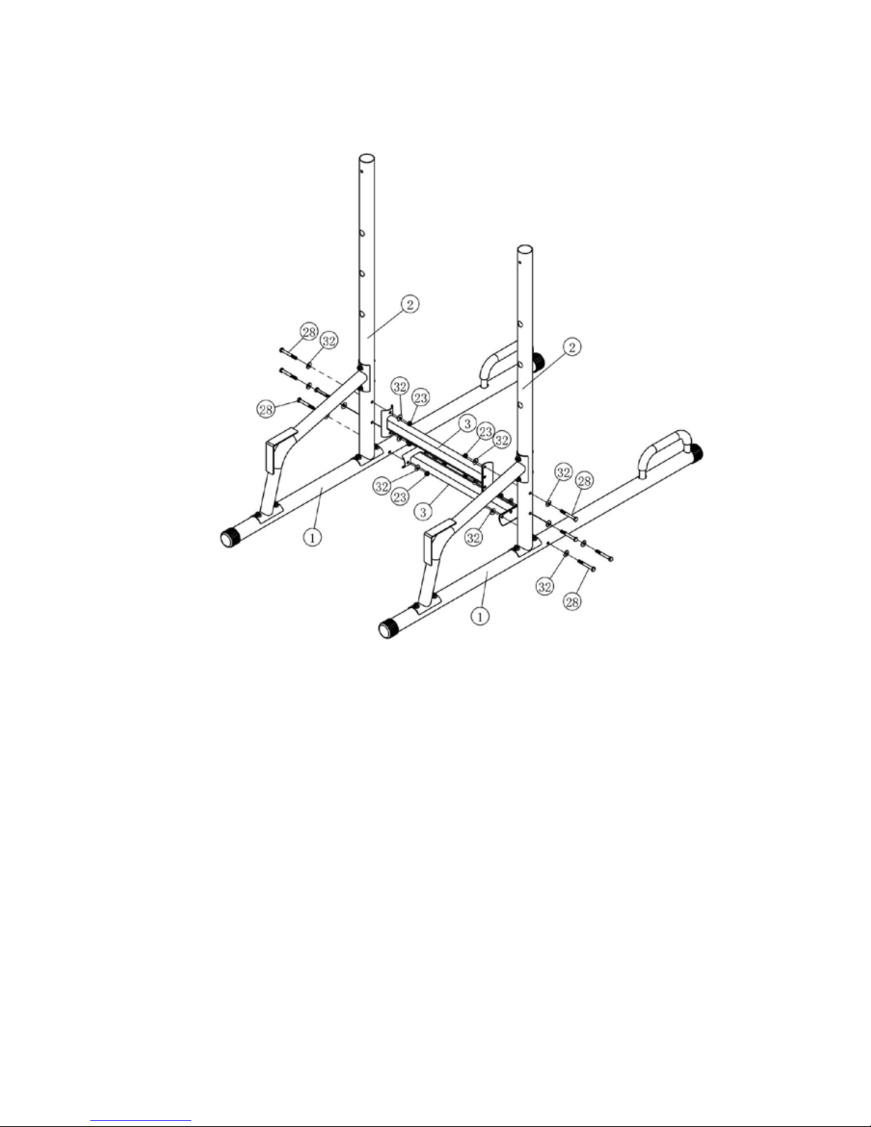
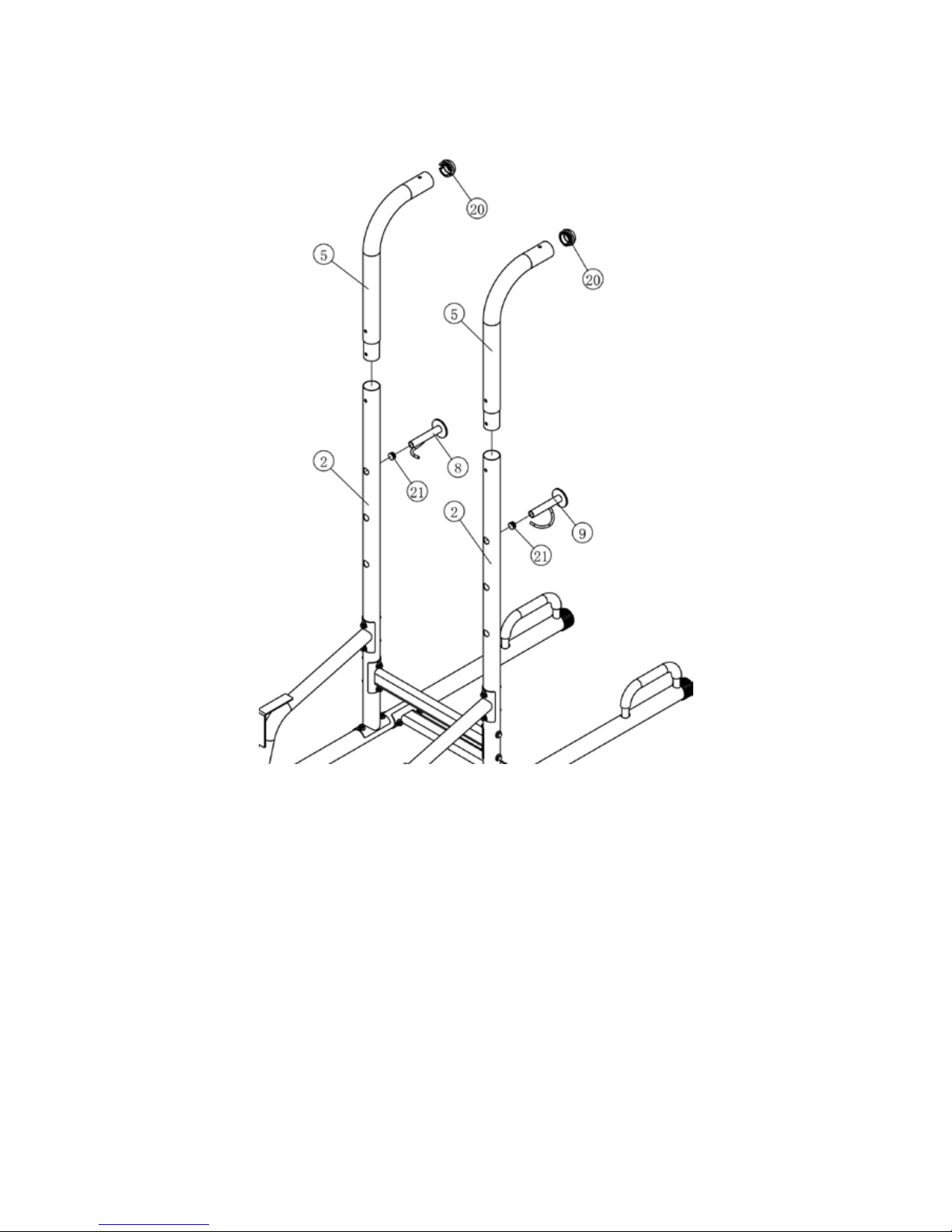
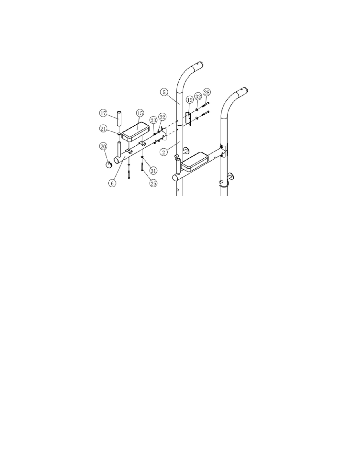
1. The equipment should only be used after a thorough review of the Owner’s Manual.
2. We recommend that two people be available for assembly of this product.
3. Keep children away from the equipment. Do not allow children to use or play on the equipment.
Keep children and pets away from equipment when it is in use.
5. It is recommended that you place this exercise equipment on an equipment mat.
6. Set up and operate equipmenton a solid level surface. Do not position equipment on loose rugs or
uneven surfaces.
7. Make sure that adequate space is available for access to and around the equipment.
8. Before using, inspect the equipment for worn or loose components, and securely tighten or
replace any worn or loose components prior to use.
9. Consult a physician prior to commencing an exercise program and follow his/her
recommendations in developing your fitnessprogram. If at any time during exercise you feel faint,
dizzy, or experience pain, stop and consult your physician.
10. Follow your physician’s recommendations in developing your own personal fitness program
10. Do not wear loose or dangling clothing while using the equipment.
11. Never exercise in bare feet or socks; always wear proper footwear such as running, walking, or
cross training shoes that fit well, provide foot support, and feature non-skid rubber soles
12. Be careful to maintain your balance while using, mounting, dismounting, or assembling the
equipment, loss of balance may result in a fall and serious bodily injury.
13.The equipment should not be used by person weight over 250 pounds, and used by only one
person at a time. This is for consumer use only. It is not for use in public or semipublic facilities.
WARNING: Before starting any exercise or conditioning program you should consult
with your personal physician to see if you require a complete physical exam. This is
especially important if you are over the age of 35, have never exercised before, are
pregnant, or suffer from any illness. READ AND FOLLOW THE SAFETY
PRECAUTIONS.
FAILURE TO FOLLOW THESE INSTRUCTIONS CAN RESULT IN SERIOUS BODILY
INJURY.
CAUTION:
Weight on this equipment not exceed 250 lbs.

3
Exploded View Diagram
Part List

4
Assembly Instruction
Step 1
Step 1
1. Slide the End Cap (19) onto the Base Frame (1). Slide the Foam (14) onto the Handle Bar
(10).
2. Insert the Handle Bar (10) into the hole of the Base Frame (1). Secure the Handle Bar (10)
using one M10x20 Hex Socket Bolt (26).
3. Attach the Upper Upright (2) to the Base Frame (1) with two M10x75 Hex Socket Bolts (27),
two 10 Arc Washers (32), and two M10 Nylon Lock Nuts (23).
4. Attach the Side Support (4) to the Upper Upright (2) with two M10x75 Hex Bolts (28), four
10 Arc Washers (32), and two M10 Nylon Lock Nuts (23).
5. Attach the Side Support (4) to the Base Frame (1) with two M10x75 Hex Socket Bolts (27),
two 10 Arc Washers (32), and two M10 Nylon Lock Nuts (23).
6. Use the same procedure to install another Base Frame (1).
Wrench tighten all bolts and nuts.

5
Step 2
Step 2
1. Attach the lower Cross Frame (3) to the right Base Frame (1) with two M10x75 Hex Bolts
(28), four 10 Arc Washers (32), and two M10 Nylon Lock Nuts (23).
2. Attach the lower Cross Frame (3) to the left Base Frame (1) with two M10x75 Hex Bolts (28),
four 10 Arc Washers (32), and two M10 Nylon Lock Nuts (23).
3. Attach another Cross Frame (3) to the Upper Upright (2) with four M10x75 Hex Bolts (28),
eight 10 Arc Washers (32), and four M10 Nylon Lock Nuts (23).

6
Step 3
Step 3
1. Insert the 60 Plug (20) into the Lower Upright (5). Insert the 25 Plug (21) into the
Left/Right Hold Frame (8,9).
2. Insert the Left/Right Hold Frame (8,9) to the Upper Upright (2) and adjust the height of the
Left/Right Hold Frame (8,9).
3. Insert the Lower Upright (5) into the sleeve of the Upper Upright (2).

7
Step 4
Step 4
1. Insert the 25 Plug (21) and the60 Plug (20) to the Arm Frame (6).
2. Attach the Arm Frame (6) and the Long Arc Plate (12) to the Lower Upright (5) and the
Upper Upright (2) with two M10x75 Hex Bolts (28), four 10 Arc Washers (32), and two
M10 Nylon Lock Nuts (23).
3. Attach the Arm Pad (15) onto the Arm Frame (6) with two M8x40 Hex Bolts (25) and two
8 Arc Washers (31).
4. Slide the 25x150 Foam Roller (17) into the Arm Frame (6).
5. Use the same procedure to install another Arm Pad (15).

8
Step 5
Step 5
1. Attach the Backrest Frame (7) to the right Arm Frame (6) with two M10x75 Hex Bolts (28),
four 10 Arc Washers (32), and two M10 Nylon Lock Nuts (23).
2. Attach the Backrest Frame (7) to the left Arm Frame (6) with two M10x75 Hex Bolts (28),
four 10 Arc Washers (32), and two M10 Nylon Lock Nuts (23).
3. Attach the Backrest Pad (16) to the Backrest Frame (7) with two M8x20 Hex Bolts (24) and
two 8 Flat Washers (30).

9
Step 6
Step 6
1. Slide the Long Foam Roller (18) and the Comfort Grip (22) onto the Pull-Up Bar (11).
2. Insert the bolt of the Pull-Up Bar (11) into the hole of the Lower Upright (5).
3. Attach the Pull-Up Bar (11) and the Short Arc Plate (13) onto the Lower Upright (5) with one
M10x105 Hex Blot (29), two M10 Nylon Lock Nuts (23), and three 10 Arc Washers (32).
Wrench tighten all bolts and nuts.
Table of contents
Other Apollo Athletics Fitness Equipment manuals
Popular Fitness Equipment manuals by other brands

Domyos
Domyos BM 530 Assembly manual

iFIT
iFIT WEIDERBLACK WBBE14908.0 user manual

Element 26
Element 26 Self-Locking Weight Lifting Belt Instructional manual

Merrithew Health & Fitness
Merrithew Health & Fitness Cardio-Tramp Rebounder owner's manual

Best Fitness
Best Fitness BFAB20R owner's manual

Body Flex Sports
Body Flex Sports PT600 owner's manual