AAN-1 & AAN-2 Hardware ManualI
© 2011 Apollo Security Inc.
Table of Contents
Part I Introduction 2
...................................................................................................................................21Overview
...................................................................................................................................22 General Features
...................................................................................................................................33Modes Of Operation
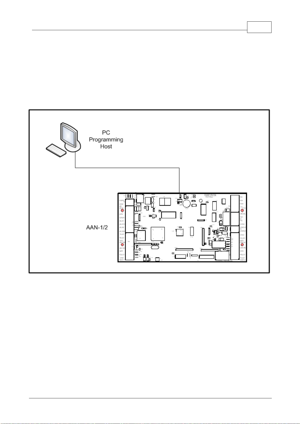
...................................................................................................................................44Programming Host
Part II Hardware Layout 6
...................................................................................................................................71Terminal Connectors
...................................................................................................................................82DIP Switches
......................................................................................................................................................... 9DIP Switch Tables
......................................................................................................................................................... 10DIP Switch Function
...................................................................................................................................103Connectors
......................................................................................................................................................... 11Device Port Communication Driver Socket
......................................................................................................................................................... 11Additional Connectors
...................................................................................................................................114 LEDs
......................................................................................................................................................... 11Start Up Mode
......................................................................................................................................................... 12Normal Operation
...................................................................................................................................125Firmware
...................................................................................................................................126Memory Backup
...................................................................................................................................137 Additional Installation Information
......................................................................................................................................................... 13Mounting Holes
Part III System Wiring 15
...................................................................................................................................151Power
...................................................................................................................................152Grounding
......................................................................................................................................................... 15DC Ground
......................................................................................................................................................... 15RS-485 Signal Ground (SG)
......................................................................................................................................................... 16Safety (Earth) Ground
......................................................................................................................................................... 16Grounding System
......................................................................................................................................................... 16Grounding Potential Difference Checks Before Connecting
...................................................................................................................................173Host Communication Connection
......................................................................................................................................................... 17Serial ......................................................................................................................................................... 18Network .................................................................................................................................................. 19ENI-100 ........................................................................................................................................... 19Introduction
........................................................................................................................................... 19Hardware Layout
...................................................................................................................................... 19Connectors
...................................................................................................................................... 19TTL Serial Connector
...................................................................................................................................... 19RJ-45 Jack
........................................................................................................................................... 20Communication Configuration
...................................................................................................................................234 Card Reader Wiring