manuals.online logo
Brands
  1. Home
  2. •
  3. Brands
  4. •
  5. Apollo
  6. •
  7. Marine Safety Device
  8. •
  9. Apollo 45681-705 User manual

Apollo 45681-705 User manual

XP95 Sounder VAD Bases
Installation Guide
General
This guide describes the installation of the following base variants
Part number Product Description Category
45681-705 XP95 Sounder VAD Base (White) with Isolator O
45681-709 XP95 VAD Base (White) with Isolator O
45681-292 White Cap only (Lockable) N/A
45681-293 Red Cap only (Lockable) N/A
Connect the devices only to control panels using the XP95 protocol.
The XP95 Sounder VAD Bases combine a sounder with a visual alarm and a detector base in one unit.
The VAD is activated whenever the sounder is active and cannot be controlled separately.
All XP95 Sounder VAD Base variants with short circuit isolator have a yellow LED which illuminates through
the moulding if a short circuit is detected on the loop wiring (see Fig 1).
Note: All XP95 Sounder VAD Base variants are not suitable for outdoor use.
Mounting Instructions
All base variants may be secured to a UK standard conduit box or surface mounted (providing there is
access through the surface for cabling). If a detector is  tted, lock it if required by screwing in the grub
screw in the detector with a 1.5mm hex driver (part no 29600-095).
The XP95 Sounder VAD Bases are ceiling mounted devices. For coverage volume information please refer
to PP2478.
Wiring Details
Note: These products are polarity sensitive (supply reversal protected) and will not function if wired
incorrectly.
Terminate all loop cables in the two way terminal blocks. Connect the incoming loop cables to L1 IN (–)
and L2 (+) and the outgoing cables to L1 OUT (–) and L2 (+). Functional earth or screen may be connected
to the EARTH connection. The isolator LED can be seen through the moulding as shown in Fig 1.
DO NOT CONNECT LOOP CABLES TO THE OUTER TERMINALS OF ISOLATED MODELS.
When using as a stand-alone unit, a cap is available (red cap part no 45681-293 or white cap part no 45681-
292) and is secured with a 1.5mm, AF hexagon socket head screw. A hexagonal driver (part no 29600-095)
is available from Apollo.
Technical Data
Operating Voltage 17—28V DC
Sounder Output
High Tone Setting Volume nominally 75dB(A) to 91dB(A)
(Complies to EN54-3)
Low Tone Setting Volume* nominally 55dB(A) to 75dB(A)
Sound pressure level information published in document PP2203 and isolator operation information
published in document PP2090, both available on request.
Current Consumption at 24V DC
Quiescent 350µA
Switch on Surge 1.2mA for 1 sec
Sounder/VAD Operating 14mA
VAD Frequency 0.5Hz
IP Rating IP21C
*Low tone setting does not comply to EN54–3 and should not be used for  re alarm applications
© Copyright Apollo Fire Detectors Limited 2013
Apollo Fire Detectors Limited, 36 Brookside Road, Havant, Hants, PO9 1JR, UK
Tel +44 (0)23 9249 2412 Fax +44 (0)23 9249 2754
Email: techsales@apollo- re.co.uk Website: www.apollo- re.co.uk
XPERT Card Addressing
Select the desired address and remove the pips indicated in black. Remove pips with a small screwdriver.
Part Number Primary Tone Secondary Tone
45681-705 Apollo Evacuation Tone 567Hz for 0.5s, 850Hz for 0.5s Apollo Alert Tone 1s off, 1s 850Hz
Tone Table
39214-788/Issue 4
1
5
www.acornfiresecurity.com
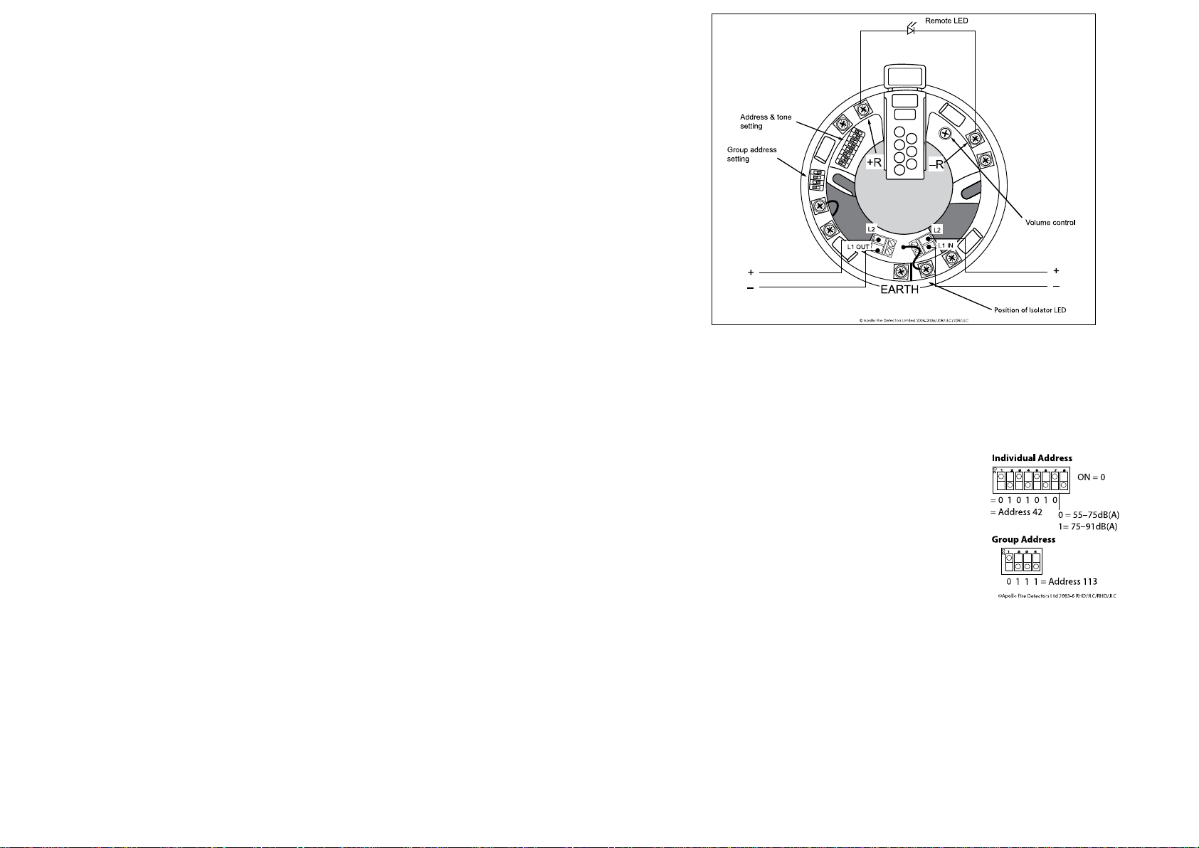
Fig. 1 Sounder VAD Base with isolator wiring
Group Addtress Settings
In group mode the XP95 Sounder VAD Base variants respond to an additional address referred to as the group
address, which is used to activate groups of base variants, Integrated Base Sounders and/or 100dB sounders
simultaneously. Individual units continue to respond to their own addresses and report their status in the normal
way. A group address is set on a four-segment DIL switch which is factory set to 0000. A group address may be
any spare address within–and only within–the range 112 to 126 inclusive. The required group address is set in
accordance with the following table. For an illustrated example, please see Fig 2.
DIL switch DIL switch DIL switch
setting setting setting
addr 1234 addr 1234 addr 1234
112 1111 117 0101 122 1010
113 0111 118 1001 123 0010
114 1011 119 0001 124 1100
115 0011 120 1110 125 0100
116 1101 121 0110 126 1000
Note: group mode is disabled if the group address DIL switch is set to 0000,
irrespective of the protocol message.
Functional Test Data
The product is controlled by the control panel using the output bits in the communication protocol.
Protocol bit use:
Output Bit Function Input Bit Function
2 group mode 2 group mode con rmed
1 = off 1 = group
0 = on 0 = individual
1 Alert tone 1 Alert tone con rmed
1 = on 1 = on
0 = off 0 = off
0 Evacuation tone 0 Evacuation tone con rmed
1 = on 1 = on
0 = off 0 = off
Commissioning
It is important that the base variants be fully tested after installation. An XP95 Test Set, part no 55000-870, may
be used to carry out functional testing of individual units. The test set can also perform data integrity tests of
an entire system.
Fault Finding
Problem Possible Cause
No response or missing Incorrect address setting
Incorrect loop wiring (polarity reversed)
Too many bases between isolators
Analogue value 1 Sounder failed
Analogue value 2 VAD failed
Analogue value 3 Sounder and VAD failed
Analogue value 4 Incorrect group address or address setting
Failure to operate Control panel has incorrect cause and effect programming
Incorrect group address setting
The address of the XP95 Sounder VAD Base variants are set using seven segments of the eight-segment DIL
switch. The eighth seg ment is used to adjust the volume output. Segments 1-7 of the switch are set to “0”
(ON) or “1”, using a small screwdriver or similar tool. A complete list of address settings is shown below. If a
detector is to be  tted, set the address as described on page 4.
DIL switch DIL switch DIL switch DIL switch DIL switch
setting setting setting setting setting
addr 1234567 addr 1234567 addr 1234567 addr 1234567 addr 1234567
1 1000000 11 1101000 21 1010100 31 1111100 41 1001010
2 0100000 12 0011000 22 0110100 32 0000010 42 0101010
3 1100000 13 1011000 23 1110100 33 1000010 43 1101010
4 0010000 14 0111000 24 0001100 34 0100010 44 0011010
5 1010000 15 1111000 25 1001100 35 1100010 45 1011010
6 0110000 16 0000100 26 0101100 36 0010010 46 0111010
7 1110000 17 1000100 27 1101100 37 1010010 47 1111010
8 0001000 18 0100100 28 0011100 38 0110010 48 0000110
9 1001000 19 1100100 29 1011100 39 1110010 49 1000110
10 0101000 20 0010100 30 0111100 40 0001010 50 0100110
51 1100110 61 1011110 71 1110001 81 1000101 91 1101101
52 0010110 62 0111110 72 0001001 82 0100101 92 0011101
53 1010110 63 1111110 73 1001001 83 1100101 93 1011101
54 0110110 64 0000001 74 0101001 84 0010101 94 0111101
55 1110110 65 1000001 75 1101001 85 1010101 95 1111101
56 0001110 66 0100001 76 0011001 86 0110101 96 0000011
57 1001110 67 1100001 77 1011001 87 1110101 97 1000011
58 0101110 68 0010001 78 0111001 88 0001101 98 0100011
59 1101110 69 1010001 79 1111001 89 1001101 99 1100011
60 0011110 70 0110001 80 0000101 90 0101101 100 0010011
101 1010011 106 0101011 111 1111011 116 0010111 121 1001111
102 0110011 107 1101011 112 0000111 117 1010111 122 0101111
103 1110011 108 0011011 113 1000111 118 0110111 123 1101111
104 0001011 109 1011011 114 0100111 119 1110111 124 0011111
105 1001011 110 0111011 115 1100111 120 0001111 125 1011111
126 0111111
2 4
www.acornfiresecurity.com
Coverage Diagram
The sides of the included rectangular coverage range from 3.06m X 6.28m
to 5.06m X 5.06m
Coverage radius of a single VAD = 2.50m
Centre dark spot radious of a single VAD = 0.97m
Depth of section from the ceiling = 2.40m
Centre to centre spacing of VADs + 1.53m
For alternative mounting heights, please contact Apollo Fire Detectors Limited
Fig 2. Example of coverage pattern
3
www.acornfiresecurity.com

This manual suits for next models

4

Popular Marine Safety Device manuals by other brands

ACR Electronics GlobalFix 2842 Product support manual

ACR Electronics

ACR Electronics GlobalFix 2842 Product support manual

ACR Electronics ResQMate RLB-40 Product support manual

ACR Electronics

ACR Electronics ResQMate RLB-40 Product support manual

Whelen Engineering Company WPA3FM installation guide

Whelen Engineering Company

Whelen Engineering Company WPA3FM installation guide

Mustang Survival khimera MD7183 owner's manual

Mustang Survival

Mustang Survival khimera MD7183 owner's manual

manuals.online logo
manuals.online logoBrands
  • About & Mission
  • Contact us
  • Privacy Policy
  • Terms and Conditions

Copyright 2025 Manuals.Online. All Rights Reserved.