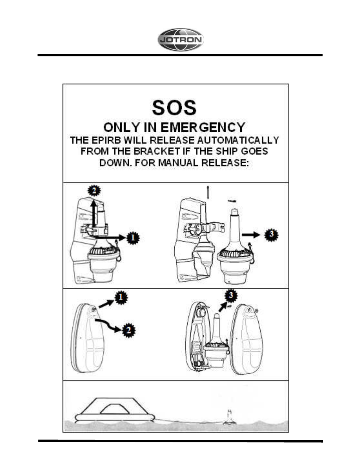
jotron Tron 40GPS Mk II User manual

82823_UM_ 40GPSMkII_E 1

2 82823_UM_ 40GPSMkII_E
EC Declaration of Conformity, available at www.jotron.com

82823_UM_ 40GPSMkII_E 3
FALSE ALERTS
DE-ALERTING SAR FORCES IN EVENT OF INADVERTENT
ACTIVATION, OR ASSISTANCE NO LONGER REQUIRED
FALSE ALARMS DIVERT RESCUE FORCES FROM REAL DISTRESS
SITUATIONS. Intentional false alerts may result in penalties.
RESPONDING TO FALSE ALARMS COSTS MILLIONS ANNUALLY.
WE NEED YOUR HELP:
1. REMEMBER: ACTIVATING YOUR BEACON IS THE EQUIVALENT OF
TRANSMITTING A MAYDAY.
2. FOLLOW MANUFACTURER PROCEDURES WHEN TESTING YOUR
BEACON.
3. IF YOUR BEACON IS ACTIVATED
•IN A NON-DISTRESS SITUATION, OR
•IN A DISTRESS SITUATION, WHICH RESOLVES, AND
YOU NO LONGER REQUIRE ASSISTANCE;
CONTACT THE NEAREST SAR AUTHORITIES VIA THE MOST
EXPEDETIOUS MEANS AVAILABLE WITH THE FOLLOWING
INFORMATION:
WARNING
USE ONLY THIS EPIRB DURING SITUATIONS OF
GRAVE AND IMMINENT DANGER
TO PERMANENTLY DISABLE EPIRB
The battery module must be removed and treated
according to chapter 6.1.2 paragraph 1, 2, 3 and 4,
chapter 6.1.3, 6.1.4, 1.1.1 and 6.1.6 in this manual.

4 82823_UM_ 40GPSMkII_E
Beacon ID number (15 character UIN):
Position (at time of activation):
Date of Activation:
Time of Activation (Time zone):
Duration of Activation:
Beacon make and model:
Vessel Name/ID:
Circumstances/cause (if known):
PRIMARY U.S. POINT OF CONTACT IS THE U.S. COAST GUARD:
PASS BY MOST EXPEDITIOUS, DIRECT MEANS TO
FOR THE PACIFIC:
PACIFIC AREA COMMAND CENTER (510) 437 3700
FOR THE ATLANTIC/GULF OF MEXICO/ATLANTIC:
ATLANTIC AREA COMMAND CENTER (757) 398-6390
OR FROM ANY LOCATION: (800) 323 SAFE
(800) 323 7233

82823_UM_ 40GPSMkII_E 5
The information in this book has been carefully checked and is believed to
be accurate. However, no responsibility is assumed for inaccuracies.
CAUTION!
This equipment contains CMOS integrated circuits. Observe handling
precautions to avoid static discharges which may damage these devices.
Jotron AS reserves the right to make changes without further notice to any
products or modules described herein to improve reliability, function or
design. Jotron AS does not assume any liability arising out of the application
or use of the described product.
Jotron AS is a prime manufacturer of safety equipment designed for rescue of human lives and
their property. For safety equipment to be effective in line with the design parameters it is
important that they are handled, stowed and maintained in compliance with the manufacturers
instructions. Jotron AS can not be held responsible for any damage caused due to incorrect use of
the equipment or breach of laid down procedures or for failure of any specific component or other
parts of the equipment.
The chapter covering battery replacement (6.1.2) is added for information only. Jotron AS does not
take any responsibility for improper disassembling/assembling of the beacon. We strongly
recommend all service to be done by authorized Jotron AS agents. In addition to normal service,
Jotron AS agents have the necessary equipment and education to test the operational functions of
the beacon. Non-original maintenance and/or service parts may destroy the equipment function and
p
erformance.

6 82823_UM_ 40GPSMkII_E
WARRANTY
All goods sold by Jotron AS are warranted to be free from defect in
workmanship and material for the period of twenty-four (24) months from
the date of delivery (unless stated otherwise and confirmed in writings).
PROVIDED:
(a) Jotron AS is given full particulars in writing of any claim prior to
the expiration of such a period and within fourteen days of the
discovery of the alleged defect.
(b) The goods have stored, installed, maintained and used properly
having regard in particular to Jotron AS specifications.
(c) Liability shall be limited at Jotron AS options to replacement or
repair or to a sum not exceeding the net invoice value of the
defective goods.
(d) Upon request the alleged faulty goods are returned to Jotron AS
at the Buyer's expense.
(e) Unless expressly stipulated in the acceptance of the order Jotron
AS gives no warranty or guarantee of the fitness or suitability of
the goods for any purpose whether disclosed or otherwise.
(f) All other warranties or conditions expressed or implied are
hereby excluded and Jotron AS shall in no circumstances be
liable for consequential damages.

82823_UM_ 40GPSMkII_E 7
Abbreviations and definitions
BAUD
Transmission rate unit of measurement for binary coded data (bit per second).
BIT
Short form of Binary Digit. The smallest element of data in a binary-coded
value.
BITE
Built in test equipment
BPS
Bits Per Second.
CHARACTER STRING
Continuous characters (other than spaces) in a message.
CHECKSUM
The value sent with a binary-coded message to be checked at the receiving end
to verify the integrity of the message.
COSPAS
COsmicheskaya Sistyema Poiska Avariynich Sudov (Space System for the
Search of Vessels in Distress)
CLOCK
A precisely spaced, stable train of pulses generated within an electronic system
to synchronize the timing of digital operations within the system.
DEFAULT
The operator initiates a condition that the navigator assumes automatically if no
other condition.
EPIRB
Emergency Position Indicating Radio Beacon

8 82823_UM_ 40GPSMkII_E
GLOBAL POSITIONING SYSTEM (GPS)
The NAVSTAR Global Positioning System, which consists of orbiting satellites,
a network of ground control stations, and user positioning and navigation
equipment. The system has 24 satellites plus 3 active spare satellites in six
orbital planes about 20,200 kilometers above the earth.
GPS
Global Position System
GPS SYSTEM TIME
Time corrected to Universal Time Coordinated (UTC) and used as the time
standard by the user segment of the GPS system.
IEC
International Electro-technical Commission.
IMO
International Maritime Organization
INTERFACE
Electronic circuits that permit the passage of data between different types of
devices; For example, the speed and heading interface circuit permits data from a
speed log and compass to pass to the navigator processor.
ITU
International Telecommunication Union.
LED
Light Emitting Diode.
LUT
Local User Terminal (Ground Station).
MCC
Mission Control Centre.
PROCESSOR
The processor circuit card in the console that controls system operations and
computes the positioning/navigation solutions.

82823_UM_ 40GPSMkII_E 9
RCC
Rescue Coordination Centre.
SARSAT
Search and Rescue Satellite-Aided Tracking System.
SBM
Shore Based Maintenance – as required by SOLAS regulation IV/15.9.2
of SOLAS 1974 as amended with, in accordance with MSC/Circ. 1039
guidelines for Shore-Based Maintenance (SBM) of Satellite EPIRBs within
5 years if:
Passenger ships (> 12 passengers) and cargo ships (> 300GT) engaged in
International voyages, shall perform SBM as follows:
-Latest by the date of the EPIRB label with this text, or the battery
Label, whichever is first.
-When this EPIRB becomes due for SBM in accordance with national
requirements.
SOFTWARE
Values programmed and preloaded into memory. The values represent a
permanent set of instructions for running the automatic functions (computations)
of the navigator.
VHF
Very High Frequency -A set of frequencies in the MHz region.
VSWR
Voltage standing wave ratio

10 82823_UM_ 40GPSMkII_E
Amendment Record
AMENDMENT
NO. INCORP.
BY DATE PAGE(S) VERSION
REASON FOR
CHANGE
1 ES 05.01.07 Total 36 A New manual
2 ES 12.04.07 Total 36 B New
company
3 ES 31.08.07 27 C Error
4 ES 31.01.08
21 and 22 D Man. operation
5 ES 25.02.08 2-6,26,30 E Added text
6
7
8
9
10
11
12
13
14
15
16
17

82823_UM_ 40GPSMkII_E 11
TABLE OF CONTENTS
1GENERAL DESCRIPTION................................................................................................16
1.1 TRON 40GPS MKII........................................................................................................................................ 16
1.2 SYSTEM DESCRIPTION ................................................................................................................................. 17
1.2.1 SIGNAL DETECTION.................................................................... 17
1.2.2 DISTRESS LOCATION DETERMINATION ............................... 18
1.2.2.1 GPS ADVANTAGE................................................................... 18
1.2.3 EPIRB REGISTRATION.................................................................. 18
2TECHNICAL SPECIFICATIONS.........................................................................................20
2.1 GENERAL ................................................................................................................................................ 20
2.2 COSPAS/SARSAT TRANSMITTER...................................................................................................................... 20
2.3 NAVIGATION DEVICE .................................................................................................................................. 20
2.4 HOMING TRANSMITTER ............................................................................................................................... 21
2.5 BRACKETS ............................................................................................................................................... 21
3FUNCTIONAL DESCRIPTION ...........................................................................................22
3.1 GENERAL ................................................................................................................................................ 22
3.1.1 EPIRB MODULE WITH ANTENNA .................................................... 22
3.1.2 BATTERY MODULE..................................................................... 23
3.1.3 EQUATOR RING WITH GASKET ...................................................... 23
4INSTALLATION ...........................................................................................................23
4.1 BRACKETS ............................................................................................................................................... 23
4.1.1 FLOAT FREE BRACKET FB5 AND FB4 ............................................... 24
4.1.2 FLOAT FREE BRACKET FBH4 ......................................................... 24
4.1.3 MANUAL BRACKET MB5 AND MB4.................................................. 24
4.1.4 MOUNTING THE FB5/MB5/FB4/FBH4/MB4 BRACKETS............................ 25
5OPERATION INSTRUCTIONS...........................................................................................25
5.1 MANUAL OPERATION .................................................................................................................................. 25
5.2 AUTOMATIC OPERATION (FB4/FBH/FB5)............................................................................................................. 26
5.3 MANUAL TEST OF THE EPIRB ......................................................................................................................... 26
6MAINTENANCE AND TROUBLESHOOTING..........................................................................27
6.1 EPIRB MODULE / BATTERY MODULE................................................................................................................. 27
6.1.1 CHANGE OF BATTERY ................................................................. 27
6.1.2 REPLACING THE BATTERY MODULE ............................................... 27

12 82823_UM_ 40GPSMkII_E
6.1.3 BATTERY DISPOSAL ................................................................... 28
6.1.4 INCINERATION .......................................................................... 28
6.1.5 LAND FILLING........................................................................... 29
6.1.6 RECYCLING.............................................................................. 29
6.2 HYDROSTATIC RELEASE REPLACEMENT............................................................................................................ 29
6.2.1 REPLACING THE RELEASE MECHANISM IN FB4/FBH4 BRACKET ............. 29
6.2.2 REPLACING THE RELEASE MECHANISM IN FB5 BRACKET ..................... 30
6.3 TRON 40GPS MKII SELF TEST.......................................................................................................................... 30
6.4 MAINTENANCE OF EPIRB .............................................................................................................................. 31
6.5 EPIRB ERROR MESSAGES .............................................................................................................................. 31
7FIGURES ...................................................................................................................32
7.1 SIGNAL DETECTION .................................................................................................................................... 32
7.2 MANUAL OPERATION .................................................................................................................................. 33
7.3 AUTOMATIC OPERATION .............................................................................................................................. 34
7.4 SELF TEST................................................................................................................................................ 34
7.5 REPLACING THE RELEASE MECHANISM IN FB4/FBH4 BRACKET.................................................................................. 35
7.6 REPLACING THE RELEASE MECHANISM IN FB5 BRACKET......................................................................................... 35
7.7 REPLACING THEBATTERY MODULE ................................................................................................................. 36
7.8 MOUNTING OF BRACKETS ............................................................................................................................ 38
8SERVICE AGENTS ........................................................................................................39

82823_UM_ 40GPSMkII_E 13
BATTERY SAFETY DATA SHEET
(Form: EEC directive 91/155)
(2) SAFETY ADVICE
S2 Keep out of reach of children.
S8 Keep container dry.
S26 In case of contact with eyes, rinse immediately with
plenty of water and seek medical advice.
S43 In case of fire, use D type extinguishers. Never use water.
S45 In case of accident or if you feel unwell, seek medical
advice immediately (show the label where possible).
(3) FIRST AID MEASURES
In case of contact of cell contents with eyes, flush immediately with water for 15 min. With skin, wash
with plenty of water and take off contaminated clothes. If inhaled, remove from exposure, give oxygen,
seek medical advice.
(4) FIRE-FIGHTING MEASURES
Extinguishing media
Suitable: Type D fire extinguishers
Not to be used: Water - CO2 - Halon, dry chemical or foam extinguishers
Special exposure hazards
Generation of chlorine, sulphur dioxide, disulphur dichloride during
thermal decomposition.
Special protective equipment
Use protective working boots, rubber apron and safety glasses with side shields.

14 82823_UM_ 40GPSMkII_E
INSTRUCTIONS FOR KEEPING THE RADIO LOG AND THE RADIO OPERATORS
OBLIGATION ACCORDING TO NATIONAL AND INTERNATIONAL REGULATION.
1. The radio log shall be kept in accordance with requirements in the Radio Regulations, SOLAS
Convention, national regulations regarding radio installations and the STCW Convention (STCW 95
including the STCW Code) including the relevant regulation regarding watch keeping on board
passenger and cargo ships.
2. Unauthorized transmissions and incidents of harmful interference should, if possible, be identified,
recorded in the radio log and brought to the attention of the Administration in compliance with the Radio
Regulations, together with an appropriate extract from the radio log. (STCW Code B-VIII/2 No.32)
TEST OF RADIO EQUIPMENT AND RESERVE SOURCE OF ENERGY
Monthly:
Float-free and manual EPIRBs to be checked using the means provided for testing on the equipment.
Check data for periodical maintenance requirement for float-free EPIRB search and rescue radar
transponders (SART) to be checked against 9 GHz radar.

82823_UM_ 40GPSMkII_E 15
TEST AND MAINTENANCE RECORD
DATE N/T/B SIGN INSP
N=NEW EPIRB INSTALLED, T=TEST, B=NEW BATTERY

16 82823_UM_ 40GPSMkII_E
1GENERAL DESCRIPTION
The Tron 40GPS MkII is emergency equipment consisting of:
• Tron 40GPS MkII COSPAS/SARSAT emergency EPIRB
• One of the following brackets:
FB4 - Automatic float free bracket.
FBH4 - Automatic float free bracket v/heating.
MB4 - Manual bracket.
MB5 - Manual bracket.
FB5 - Automatic float free bracket.
The Tron 40GPS MkII EPIRB is developed to meet the regulations and rules for use on vessels and life rafts in the
maritime service. Tron 40GPS MkII meets the following specifications for 406 MHz EPIRBs for use in search and
rescue operations at sea:
IEC 61097-2
IEC 60945
MSC/Circ 862
C/S T.001
IMO A662(16)
IMO A696 (17)
IMO A810 (19)
DIR 96/98 EEC
1.1 TRON 40GPS MkII
The Tron 40GPS MkII is buoyant, and is designed to automatically release and activate in case of an emergency where
the EPIRB and its bracket is submerged into the sea. The Tron 40GPS MkII can also be operated as a manual EPIRB,
by manually releasing it from its bracket and then activating it.
Five different brackets are currently available for the Tron 40GPS MkII. MB4 and MB5 are the manual bracket and
FB4 and FBH4 is the automatic bracket. FB5 is automatic bracket with cover. The manual bracket comes without the
hydrostatic release mechanism and is used to store the beacon inside the wheelhouse or other protected places. The
automatic bracket is mounted in a free space outside where the beacon can be released automatically.
The purpose of the Tron 40GPS MkII is to give a primary alarm to the search and rescue authorities. The EPIRB gives
an immediate alarm when activated, transmitting the ID of the ship in distress. Care must be taken not to activate the
EPIRB unless in an emergency situation, in such cases the user will be held responsible. For periodic testing a test
function is implemented. During the test cycle the EPIRB does a self-test on the transmitters and on the battery status.
No emergency signal is transmitted during the self-test.
The battery of the EPIRB will last for at least 48 hours from activation of the EPIRB.

82823_UM_ 40GPSMkII_E 17
1.2 SYSTEM DESCRIPTION
The COSPAS/SARSAT system was introduced in 1982 as a worldwide search and rescue system with the help of
satellites covering the earth’s surface. Since the introduction of the system more than 20531 persons have been rescued
by the COSPAS/ SARSAT system (2005). Currently the system consists of 5 functional
satellites in a polar orbit constellation, these satellites cover the entire earth’s surface and receive the emergency signal
from the 406 MHz transmitter within the Tron 40GPS MkII, more polar orbiting satellites will be available in the
future, giving a faster location and rescue time.
In addition several geostationary satellites are equipped with a 406 MHz transponder, these satellites are not able to
locate the Tron 40GPS MkII but will give an early warning to the rescue forces, minimising the time from an
emergency occurs till the rescue forces are at the site.
Each emergency EPIRB in the system is programmed with its own unique code, therefore it is vital that the ships data
that is given to the dealer you obtained your Tron 40GPS MkII, is correct. It is also important that your EPIRB is
registered in the database for each country. This database is normally located in the same country that the ship is
registered.
1.2.1 SIGNAL DETECTION
See figure 7.1.a
When the Tron 40GPS MkII is activated (manually or automatically) it transmits on the frequencies 121.5 MHz and
406.037 MHz. An analogue signal is emitted on 121.5 MHz and a digital signal is transmitted on 406.037 MHz. After
the Tron 40GPS MkII is activated, the next passing satellite will detect the transmitted signal and relay it to an antenna
at a ground station, called an LUT.
For the 121.5 MHz signal the satellite must be within line of sight of both the Tron 40GPS MkII and a ground station.
The ground station or LUT has a 2500 km satellite reception radius centred at the LUT. In areas without LUT coverage
(mostly less populated areas in the southern hemisphere), signals from the 121.5 MHz transmitter will not be detected
by the satellites, only by passing aircraft’s. This is not the case with the 406 MHz transmitter, because the satellites
have a memory unit, which stores the signals for relay to the next available LUT giving it a truly global coverage.
Once the signal is received by the LUT, it is processed for location and sent to a Mission Control Centre (MCC). The
MCC sorts the alert data according to geographic search and rescue regions and distributes the information to the
appropriate Rescue Co-ordination Centre (RCC), or if outside the national search and rescue area, to the appropriate
MCC that covers the area where the distress signal was detected. The RCC in turn takes the necessary action to initiate
search and rescue activities.

18 82823_UM_ 40GPSMkII_E
The International Cospas-Sarsat System will cease satellite processing of 121.5/243 MHz beacons from 1 February
2009. From that date only 406 MHz beacons will be detected by the Cospas-Sarsat satellite system. This affects all
maritime beacons (EPIRBs), all aviation beacons (ELTs) and all personal beacons (PLBs).
1.2.2 DISTRESS LOCATION DETERMINATION
See figure 7.1.b
The location of the distress signal is determined by taking measurements of the doppler shift of the EPIRB frequency
when the satellite first approach and then pass the EPIRB.
The actual frequency is heard at the time of closest approach (TCA). Knowing the position of the satellite and using the
received doppler signal information, it is possible to determine the location of the Tron 40GPS MkII from the satellite
at the TCA. At the LUT, actually two positions are calculated. One is the actual position (A) and the other is the mirror
image (B) position. A second satellite pass confirms the correct location (A). With the 406 system the real solution can
be determined on the first pass with a reliability of nearly 90% and down to an accuracy of less than 5 km (3.1 miles).
1.2.2.1 GPS ADVANTAGE
Tron 40GPS MkII has been designed to operate with the Cospas-Sarsat system and will enhance further the lifesaving
capabilities of conventional beacons. The integrated 12 channel GPS module accept continuous positional information
from the standard GPS system using 27 satellites providing an accuracy of approximately 100m. Upon activation of the
Tron 40GPS MkII in an emergency situation, the positional information is incorporated into the distress message
transmitted to the LUT. The main advantage with integrated GPS in Tron 40GPS MkII is the rapid response and
positional accuracy, providing vital information during a rescue operation practically eliminating valuable time spent
searching for the distressed. Whenever a distress message transmitted by Tron 40GPS MkII is detected by polar orbit
satellite (LEOSAR) the delayed alert remains the same as for non-GPS integrated EPIRBs (max. 90 minutes), but the
position accuracy is improved.
1.2.3 EPIRB REGISTRATION
Normally the MCC will contact the vessel or the contact person registered in a shipping register and/or an EPIRB
register (Ships owner, family member etc.) before alerting the RCC. This is to determine if the alarm from the EPIRB
for some reason is a false alarm, and an expensive rescue operation can be avoided. Because of this it is important that
the ships data is correct in the shipping register or in the EPIRB database.
Tron 40GPS MkII purchased in some countries will have a registration form attached to it, it is important that this
registration form is completed by the owner and returned to the place the EPIRB was purchased or to the address
specified on the registration form.
Other countries use the already available shipping register to obtain the necessary information for a vessel in distress, in
these countries the ship is already registered and no registration form is necessary, however it is vital that the coding of

82823_UM_ 40GPSMkII_E 19
the Tron 40GPS MkII is kept up to date with data on the ship (nationality, call sign, etc.), to minimize the time from an
alarm to the start of the search and rescue operation. Reprogramming the Tron 40GPS MkII can be done at authorized
Jotron AS agents in more than 180 different places throughout the world.
If you are a resident of the United States, you must register this beacon with the National Oceanic and Atmospheric
Administration (NOAA) using the registration card included with the unit. Fill out the form and send it to:
SARSAT Beacon Registry, NOAA-SARSAT, E/SP3, FB4, Room 3320, 5200 Auth Road, Suitland, MD 20746-4304
Vessel owners shall advise NOAA in writing upon change of vessel or EPIRB ownership. Transfer of EPIRB to
another vessel, or any other change in registration information, NOAA will provide registrants with proof of
registration and change of registration postcards.

20 82823_UM_ 40GPSMkII_E
2TECHNICAL SPECIFICATIONS
2.1 GENERAL
Battery: Lithium , SAFT LSH14L, 5 years service life.
Housing: Polycarbonate w/ 10% glassfibre
Dimensions: Height: 379 mm
Max diameter: 180 mm, Weight app:. 2.0 kg
Materials: Polycarbonate.
Compass safe distance: 1.5 m
Temperature range: -20oC to + 55oC
Operating life: Minimum 48 hours at -20oC
2.2 COSPAS/SARSAT TRANSMITTER
Frequency: 406.037 MHz - + 2 ppm
Output power: 5W -+ 2 dB
Protocols: Tron 40GPS MkII: Maritime, Serialized, Radio Call sign
Modulation: Phase modulation 1.1 -+ 0.1 rad
Data encoding: Bi Phase L
Stability: Short term <- 10-9
Medium term <- 10-9
Residual noise <- 3x10⁻⁹
Bit rate: 400 b/s
Antenna: Built in, omnidirectonal.
2.3 NAVIGATION DEVICE
Type: iTrax03-S, 12 Channel GPS Receiver
Frequency: L1 frequency band
Antenna: Patch type
Table of contents
Other jotron Marine Safety Device manuals