Applied Membranes W-G2162EM Instruction Manual

Industry Leader in RO Expertise and Membrane Applications since 1983™
Systems Membranes & Chemicals Filters
2325 Cousteau Ct. Vista, CA 92081 • (760) 727-3711 • FAX: (760) 727-4427
Revision: 06-26-2013
Manual for
Operation & Maintenance
Of
Carbon Filter with
Metered Valve
for Models:
W-G2162EM & W-G2472EM

Installation and Service Manual – Metered Carbon Filter
Page 2
Copyright © 2012 Applied Membranes, Inc. All Rights Reserved.
Panel Operation Quick Reference Guide
User Display When in normal operation, one of five displays may be shown. Pressing NEXT will alternate between the displays.
User Screen 1: Typical user display. Shows volume remaining (in gallons)
until next regeneration.
User Screen 2: Displays number of days to next regeneration.
User Screen 3: Displays flow rate in gallons per minute.
User Screen 4: Displays total flow in gallons since last reset.
(Press and hold ▼for 3 seconds to reset to 0.)
User Screen 5: Shows current time.
User screens 1, 3 and 4 will not be shown if 7 or 28 day options are selected in configuration settings.
Regeneration Screens
During Regeneration: The display shows the time remaining in the current cycle.
Pressing “REGEN” will advance to the next cycle.
Set Time of Day
In the event of a prolonged power
outage, time of day flashes,
indicating that it needs to be reset.
All other information will be stored in
memory no matter how long the
power outage. Please complete the
steps as shown to the right.
(Time of day will only need to be set when a
power outage lasts more than 8 hours, or
when daylight savings time begins or ends.)
Press NEXT until the time of day screen is
displayed.
Press and hold ▲or ▼until the SET indicator is
displayed and the hour flashes.
Press ▲or ▼until the correct hour is displayed.
Press NEXT, the minutes will flash.
Press ▲or ▼until the correct minute is
displayed.
Press NEXT to return to the display screen.
Button Operation and Function
Scrolls to the Next Display
Press once and release to schedule a regeneration at the preset delayed regeneration
time. (Press and release again to cancel the regeneration.)
Press and Hold for 3 seconds to initiate an immediate regeneration.
While Regeneration is in Process: Press to advance to the next cycle.
While in Programming Screens: Press to go backwards to the previous screen.
Changes variable being displayed.
Key sequence to lock and unlock program settings.
Press and Hold for 3 seconds to initiate a control reset. The software version is displayed
and the piston returns to the home/service position, resynchronizing the valve.
Error Message
If the word “ERROR” and a number are flashing on the display, check the trouble shooting section of
this manual to identify the error. Clear error by disconnecting the power supply at the PC board and
reconnecting, or press the NEXT & REGEN buttons simultaneously for 3 seconds.
Manual Regeneration
Delayed Regeneration: Press and Release the “REGEN” button.
“◄” will flash towards REGEN. Regeneration will be performed “tonight” at the preset time
of day. (Cancel request by pressing the “REGEN” button again.)
Immediate Regeneration: Press and Hold the “REGEN” button for approximately 3
seconds. Regeneration will begin immediately. Request cannot be cancelled.

Installation and Service Manual – Metered Carbon Filter
Page 3
Copyright © 2012 Applied Membranes, Inc. All Rights Reserved.
TableofContents
Design Basis & Specifications.............................................................................................................................................4
General Information and Safety...........................................................................................................................................4
Installation .............................................................................................................................................................................4
Location...............................................................................................................................................................................4
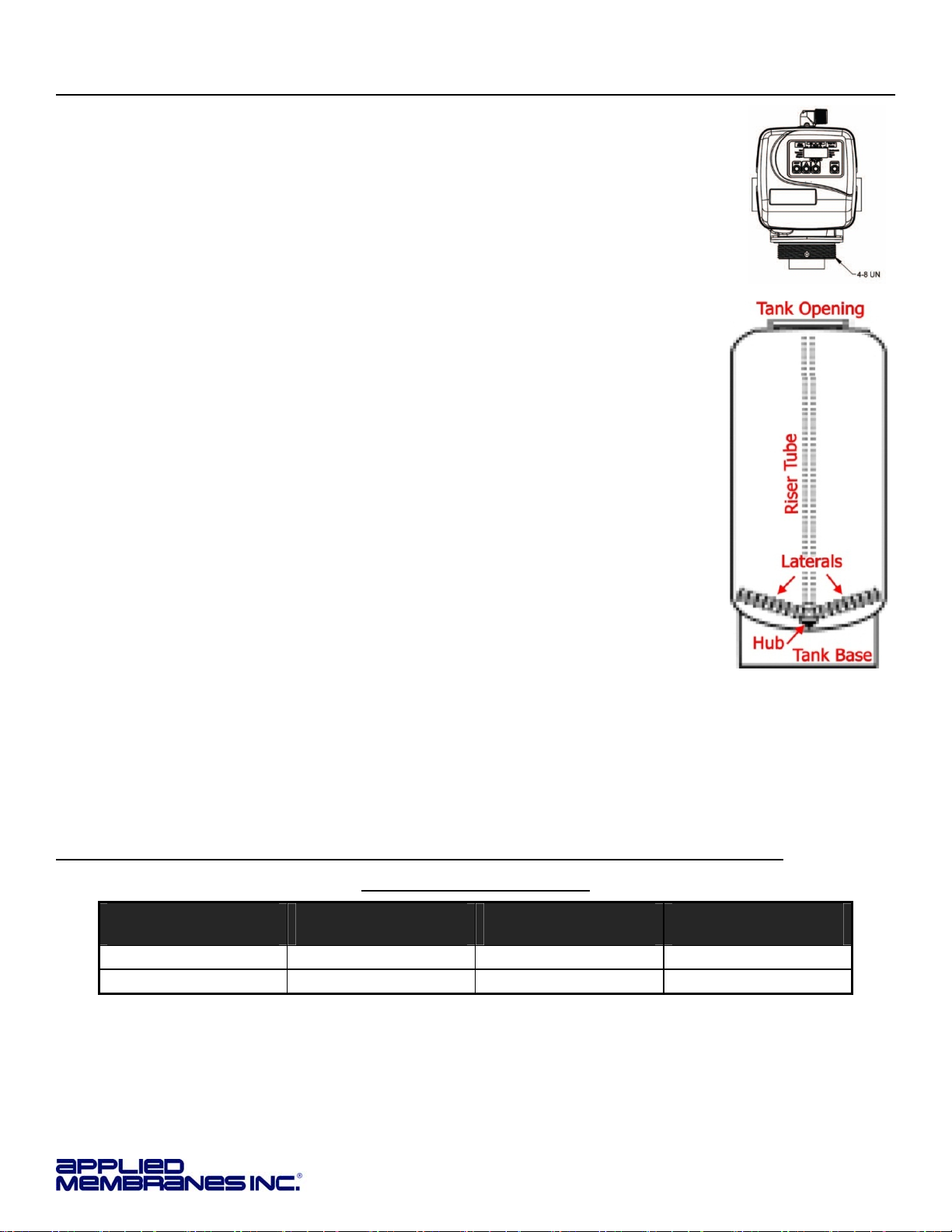
Loading the Media...............................................................................................................................................................5
MediaQuantity per Model ....................................................................................................................................................5
Plumbing..............................................................................................................................................................................6
Operating Do’s and Don’ts...................................................................................................................................................7
Initial Start-Up........................................................................................................................................................................8
System Monitoring and Record Keeping............................................................................................................................8
Operating Conditions ...........................................................................................................................................................8
Control Valve Operation & Service .....................................................................................................................................9
Control Valve Specifications................................................................................................................................................9
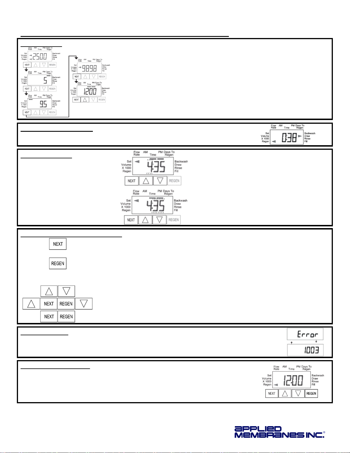
User Display ......................................................................................................................................................................10
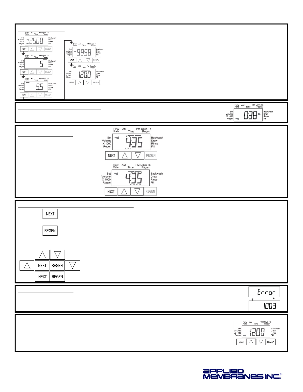
Regeneration Screens.......................................................................................................................................................10
Set Time of Day.................................................................................................................................................................10
Button Operation and Function .........................................................................................................................................10
Error Message...................................................................................................................................................................10
Manual Regeneration........................................................................................................................................................10
General Warnings & Site Requirements ...........................................................................................................................11
Control Valve General Features and Information..............................................................................................................11
Configuring and Programming Control Valve Options...................................................................................................11
Metered Backwash Filter Recommended Programming Overview...................................................................................12
Configuration Settings (Pre-Programmed to Factory Defaults).......................................................................................13
Regeneration Cycle Time Settings (Pre-Programmed to Factory Defaults)..................................................................14
Installer Displays and Settings for Control Valve Options.................................................................................................15
Diagnostics........................................................................................................................................................................17
Control Valve Drawings and Components.......................................................................................................................18
CV1.5 Overview Drawings.................................................................................................................................................18
CV1.5 Drive Cap Assembly, Downflow Piston, Regenerate Piston & Spacer Stack Assembly ......................................19
CV1.5 Injector Valve Body, Refill Flow Control and Injector Plug.....................................................................................20
CV1.5 Drain Line Flow Controls........................................................................................................................................21
Meter Assembly.................................................................................................................................................................22
CV1.5 Flow Diagram, Service ...........................................................................................................................................23
CV1.5 Flow Diagram, Backwash.......................................................................................................................................23
CV1.5 Flow Diagram, Rinse..............................................................................................................................................24
Service Spanner Wrench...................................................................................................................................................24
Control Valve Service Instructions ...................................................................................................................................25
Drive Assembly..................................................................................................................................................................25
Drive Cap Assembly..........................................................................................................................................................26
Main Piston........................................................................................................................................................................26
Spacer Stack Assembly.....................................................................................................................................................27
Injector Cap, Screen, and Injector Plug.............................................................................................................................27
Refill Port Plug...................................................................................................................................................................27
Drain Line Flow Control.....................................................................................................................................................27
Meter Assembly Service Instructions ................................................................................................................................27
Maintenance – Removal & Replacement of Carbon Media.............................................................................................28
Troubleshooting..................................................................................................................................................................29
Product Warranty................................................................................................................................................................32

Installation and Service Manual – Metered Carbon Filter
Page 4
Copyright © 2012 Applied Membranes, Inc. All Rights Reserved.
DesignBasis&Specifications
Table 1 – Design Basis
Model No.* Flow Rate**
(gpm)
Backwash
Flow**
(gpm)
Volume of Media
(cu.ft.)
Resin Tank
(Dia”×H”)
Valve & In/Out
Conn.
5gpm/ft
2
15gpm/ft
2
Carbon (only) Total (Incl.
Underbed)
W-G2162EM 13 36 25 6 7 21 × 62 1.5”
W-G2472EM 15 47 35 8 10 24 × 72 1.5”
*
Filters are available with USA or European style plugs and voltages.
W-G2162EM-US & W-G2472EM-US = 120V AC/60Hz with USA cord
W-G2162EM-EU & W-G2472EM-EU = European 220V AC (EU plug is removable to convert into universal 220v cord)
**
Backwash flow rate based on 25 psi pressure drop.
Operating Limits: Vessel rated at 150 psi max. operating pressure, 120°F max. operating temp.
GeneralInformationandSafety
DISCLAIMER:
The information contained in this document is subject to change
without notice. Applied Membranes, Inc. shall not be liable for
technical or editorial omissions made herein; nor for incidental or
consequential damages resulting from the furnishing,
performance, or use of this material.
READ THIS MANUAL:
Prior to operating or servicing this unit, this manual must be read
and understood. If anything is not clear, call for assistance before
proceeding. Keep this and other associated manuals for future
reference and for new operators or qualified service personnel.
USE PROPER POWER CONNECTIONS:
Use proper wiring and connection methods to satisfy local
electrical codes. SHOCK HAZARD: Connect this unit to a
properly grounded connection in accordance with the National
Electrical Code. DO NOT, under any circumstances, remove the
ground wire or ground prong from any power plug. Do not use
extension cords or an adapter without proper consideration.
SERVICE WARNING:
To prevent electrical shock, disconnect power to the system
prior to servicing.
WARNING:
Do not make any alteration or modification in the wiring or
plumbing of the system. This can result in damage to the
system and cause injury to operators or users.
WARNING:
Flush the system for at least 30 minutes before use to
remove all chemicals present.
CAUTION:
Never let the filter freeze. Freezing can damage the resin
tank.
Installation
Unpack the filter. Inspect assemblies for damage (cracked couplings, broken or split pipes, loose straps, etc.).
Location
Select a location for the filter with adequate clearance from walls and other equipment to allow access on all sides of the
tank. The unit must be located near a drain able to accommodate the backwash flow rate of your unit (see the table on
page 4). This is in addition to any other equipment sharing the drain.
Select a location for the brine tank that is accessible for easy refilling. Ensure floor beneath the brine tank is clean and
level.
A grounded power supply of the appropriate voltage and a local disconnect switch is required.
Caution:
The unit must not be located near any corrosive chemicals, or in an area where the
temperature may exceed 113°F (45°C). Do not install any water conditioner with less than 10 feet of piping
between its outlet and the inlet of a water heater.
Warning:
The power supply must be properly grounded to avoid injury from electrical shock.

Installation and Service Manual – Metered Carbon Filter
Page 5
Copyright © 2012 Applied Membranes, Inc. All Rights Reserved.
LoadingtheMedia
1. Place tank on a level, solid surface in the correct position for installation. Lift the riser tube
from the tank, keeping the attached hub within the opening of the tank. Within the tank,
assemble the laterals onto the hub, twisting each lateral into the hub to lock securely.
Gently lower the assembly to the bottom of the tank. The top of the riser tube should be
about level with the top of the tank.
2. The “riser tube” inside the media/resin tank delivers treated water to your control valve. It
will need to be temporarily covered with tape on the top end to prevent anything from falling
down inside the tube during loading.
3. Step back and look at the tank to make sure it is standing straight, and not tilted. The black
base on the bottom of the tank should also be straightened before filling the tank. If your
tank is tilted, simply pick up the tank 2-3 inches off the floor and drop it gently (but firmly)
down, favoring the side of the base that needs to be adjusted.
4. Before loading the media, fill the tank with 2-3 feet of water (or 1/3 full, depending on the
tank size), to soften the fall of the rocks and prevent damage to the distributor. To load the
media, use a funnel in the top of the media tank with the riser tube still inside. Make sure
the riser tube is covered with tape to keep media out.
5. Scoop the media into the funnel, slowly letting it fall down inside the media tank around the
riser tube. Fill the tank with the media provided, pouring the media in the following order
(1stwill end up on the bottom of the tank, last will end up at the top of the tank, etc.). Note:
The tank will be approximately ½ - ⅔full after loading is complete. Refer to Table 2 for the
proper quantities of each media.
I. Gravel – YMGRVL11618 – 1 CF (100 lbs.) per bag
II. Gravel ¼” × ⅛” – YMGRVL1418 – 0.5 CF (50 lbs) per bag (not used in W-G2162EM)
III. YMC1240RCOAL – 1 CF (27.5 lbs.) per bag
6. Remove the funnel from the top of the tank, and the tape from the end of the riser tube.
Brush any loose media or resin off the top opening of the tank.
7. The bottom of the control valve has an opening with O-rings inside; lubricate the O-ring with a non-petroleum based
lubricant. Position the valve over the top of the media tank, making sure the top of the riser tube inserts inside the
opening in the bottom of the valve.
8. Screw the valve down into the media tank. Another person should hold the tank as the valve is being snugly tightened
onto the tank. Do not over-tighten. Tighten until snug, tighten a bit more, then STOP. The large o-ring will seal itself.
MediaQuantityperModel
Table 2 –Media Quantities
Model No.*
(-US or –EU) Gravel 1
/
16 ×⅛
I Gravel ¼ × ⅛
II Carbon
III
W-G2162EM 1 CF (100 lbs) N/A (0) 6 CF (165 lbs)
W-G2472EM 1 CF (100 lbs) 1 CF (100 lbs) 8 CF( 220 lbs)

Installation and Service Manual – Metered Carbon Filter
Page 6
Copyright © 2012 Applied Membranes, Inc. All Rights Reserved.
Plumbing
Note:
All plumbing is to be done in accordance with state and local codes.
Caution:
Before placing wall anchors to support piping ensure that no electrical conduit or wiring is located
behind the intended mounting location.
Note:
The control valve, fittings and/or bypass are designed to accommodate minor plumbing misalignments
but are not designed to support the weight of a system or the plumbing.
Note:
Connect to a supply line downstream of outdoor spigots. Install an inlet shutoff valve and plumb them
to the unit’s inlet. Installation of a bypass valve is recommended. If using plastic fittings, ground the water
conditioner per local electrical codes. If a water meter is used, install the water meter on the outlet side of the
control valve. The turbine assembly may be oriented in any direction, but is usually oriented pointing up to reduce
drainage out of the pipe during service.
Note:
Do not use pipe dope or other sealant on threads. Use teflon tape on threaded inlet, outlet and drain
fittings.
1. Install connecting piping between raw
water source and input pipe on control
valve.
2. Install drain line from control valve to
a free flowing drain.
A 1.25” Male NPT × 1.5” Female NPT SS
drain flow control is installed on the valve.
Solder joints near the drain must be done
prior to connecting the drain line flow
control fitting. Leave at least 6”
(152.4mm) between the drain line flow
control itting and the solder joints to
prevent heat from damaging the flow
control. Avoid elevating the drain line
above the control valve where possible.
Discharge the drain line through an air
gap to a receptacle in accordance with
local plumbing codes.
Important:
Never insert a drain line directly into a drain, sewer line or trap. Always allow an air gap between
the drain line and the receptacle to prevent back siphonage.
3. Install the water meter on the outlet side of the control valve.
The meter may be threaded directly into the valve or may be
plumbed separately downstream of the unit*. Ensure the arrow on
the meter body is going the same direction as the water flow. The
turbine assembly may be oriented in any direction, but is usually
oriented pointing up to reduce drainage out of the pipe during
service. Meter can be installed horizontally or vertically.
*A longer cable (Part #V3221) is required for distances longer than 3” from
the valve body.

Installation and Service Manual – Metered Carbon Filter
Page 7
Copyright © 2012 Applied Membranes, Inc. All Rights Reserved.
4. Connect the meter cable: Remove the valve cover
and strain relief cover on rear of valve. Bring meter
cable through the knockout hole in the back of the
valve and connect to the three-pin connection labeled
“METER” on the PC board. Weave the meter cable
through the strain relief and replace the cover and
fastening screw.
Ensure meter cable is connected to the meter
assembly. See “Meter Service Instructions” in the
“Control Valve Service Instructions” section of this
manual for detailed meter disassembly and
reassembly instructions.
5. Install piping between meter output and point of use.
OperatingDo’sandDon’ts
DO:
Monitor system and keep a log.
Maintain proper water pressure for backwashing.
DON’T:
Permit oils or fats in feed water.
Shut down system for extended periods.
Exceed operating pressures or temperatures.
Backwash filter with insufficient water flow.

Installation and Service Manual – Metered Carbon Filter
Page 8
Copyright © 2012 Applied Membranes, Inc. All Rights Reserved.
InitialStart-Up
1. Check all piping connections and make sure feed valves are open. Inspect plumbing for leaks.
2. Check that control valve is connected to electrical source.
3. Open Raw Water source valve.
Note:
Check for leaks throughout system as pressure is applied.
4. Fully open a cold water faucet downstream of the system. Allow water to run until clear. Close the cold water
faucet.
5. Turn off the supply water.
6. Initiate manual backwash of the control valve: Press and hold the REGEN button for three seconds until the drive
motor starts. Press the REGEN button to advance the unit into the backwash cycle. Wait until the motor stops
and the backwash time begins to count down.
7. Open the inlet water supply valve very slowly, allowing the water to fill the tank in order to expel air.
Caution:
If water flows too rapidly, there will be a loss of media out the drain.
8. When water is flowing steadily to the drain without the presence of air, fully open the water supply inlet valve.
Press the REGEN button again to advance to the rinse position and allow the water to run to drain for 2-3 minutes
or until the drain runs clear.
9. Press the REGEN button to advance to the service position.
10. Review the control valve operations section of this manual and ensure settings are properly programmed before
placing the carbon filter in service.
System Monitoring and Record Keeping
Monitor filter and record all pertinent data. This data is needed to determine operating efficiency and for performing
system maintenance. The latter includes changing of the media, pressure drop across the mineral tank and control valve.
Note:
Warranty Claims cannot be processed without adequate operating data and filter history.
OperatingConditions
For optimum filter performance, observe the following:
Maintain a minimum of 25 psi during backwash cycle.
Water pressure should not exceed 120 psi across mineral tank.
Water temperature should not exceed 110 °F.
CAUTION: Hydrocarbons such as kerosene, benzene, gasoline, etc., may damage products that
contain o-rings or plastic components. Exposure to such hydrocarbons may cause the products to leak. Do
not use the product(s) contained in this document on water supplies that contain hydrocarbons such as
kerosene, benzene, gasoline, etc.

Installation and Service Manual – Metered Carbon Filter
Page 9
Copyright © 2012 Applied Membranes, Inc. All Rights Reserved.
Control Valve Operation & Service
CV1.5 Control Valve
Control Valve Specifications
Minimum/Maximum Operating Pressures: 20 psi (138 kPa, 1.4 bar) to 125 psi (862 kPa, 8.6 bar)
Minimum/Maximum Operating Temperatures: 40°F (4°C) to 110°F (43°C)
No user serviceable parts are on the PC board, the motor, or the power adapter. The means of disconnection from the
main power supply is by unplugging the power adapter from the wall.

Installation and Service Manual – Metered Carbon Filter
Page 10
Copyright © 2012 Applied Membranes, Inc. All Rights Reserved.
User Display
When in normal operation, one of five displays may be shown. Pressing NEXT will alternate between the displays.
User Screen 1: Typical user display. Shows volume remaining (in gallons)
until next regeneration.
User Screen 2: Displays number of days to next regeneration.
User Screen 3: Displays flow rate in gallons per minute.
User Screen 4: Displays total flow in gallons since last reset.
(Press and hold ▼for 3 seconds to reset to 0.)
User Screen 5: Shows current time.
User screens 1, 3 and 4 will not be shown if 7 or 28 day options are selected in configuration
settings.
Regeneration Screens
During Regeneration: The display shows the time remaining in the current cycle.
Pressing “REGEN” will advance to the next cycle.
Set Time of Day
In the event of a prolonged power
outage, time of day flashes,
indicating that it needs to be reset.
All other information will be stored
in memory no matter how long the
power outage. Please complete
the steps as shown to the right.
(Time of day will only need to be set when a
power outage lasts more than 8 hours, or
when daylight savings time begins or ends.)
Press NEXT until the time of day screen is
displayed.
Press and hold ▲or ▼until the SET indicator is
displayed and the hour flashes.
Press ▲or ▼until the correct hour is displayed.
Press NEXT, the minutes will flash.
Press ▲or ▼until the correct minute is
displayed.
Press NEXT to return to the display screen.
Button Operation and Function
Scrolls to the Next Display
Press once and release to schedule a regeneration at the preset delayed regeneration
time. (Press and release again to cancel the regeneration.)
Press and Hold for 3 seconds to initiate an immediate regeneration.
While Regeneration is in Process: Press to advance to the next cycle.
While in Programming Screens: Press to go backwards to the previous screen.
Changes variable being displayed.
Key sequence to lock and unlock program settings.
Press and Hold for 3 seconds to initiate a control reset. The software version is displayed
and the piston returns to the home/service position, resynchronizing the valve.
Error Message
If the word “ERROR” and a number are flashing on the display, check the trouble shooting section of
this manual to identify the error. Clear error by disconnecting the power supply at the PC board and
reconnecting, or press the NEXT & REGEN buttons simultaneously for 3 seconds.
Manual Regeneration
Delayed Regeneration: Press and Release the “REGEN” button.
“◄” will flash towards REGEN. Regeneration will be performed “tonight” at the preset time of
day. (Cancel request by pressing the “REGEN” button again.)
Immediate Regeneration: Press and Hold the “REGEN” button for approximately 3
seconds. Regeneration will begin immediately. Request cannot be cancelled.

Installation and Service Manual – Metered Carbon Filter
Page 11
Copyright © 2012 Applied Membranes, Inc. All Rights Reserved.
General Warnings & Site Requirements
The control valve, fittings and/or bypass are designed to
accommodate minor plumbing misalignments but are not
designed to support the weight of a system or the plumbing.
Do not use Vaseline, oils, other hydrocarbon lubricants or
spray silicone anywhere. A silicone lubricant may be used on
black o-rings but is not necessary
Hydrocarbons such as kerosene, benzene, gasoline, etc., may
damage products that contain o-rings or plastic components.
Exposure to such hydrocarbons may cause the products to leak.
Do not use the product(s) contained in this document on water
supplies that contain hydrocarbons such as kerosene, benzene,
gasoline, etc.
Teflon tape is recommended to be used on all threads. Do
not use pipe dope, as it may break down the plastics in the control
valves.
The plug in power adapter is for dry locations only, and should
be connected to an uninterrupted outlet installed within 15 feet
(4.57 meters) of the water conditioner.
All plumbing should be done in accordance with local
plumbing codes.
Solder joints near the drain must be done prior to connecting
the drain line flow control fitting. Leave at least 6” between the
drain line control fitting and solder joints when soldering pipes that
are connected on the drain line control fitting. Failure to do this
could cause interior damage to the drain line flow control fitting.
Plug into an electrical outlet. Note: All electrical connections
must be connected according to local codes. (Be certain the outlet
is uninterrupted.) Install grounding strap on metal pipes.
After completing any valve maintenance involving the drive
assembly or the drive cap assembly and pistons unplug power
source jack from the printed circuit board (black wire) and plug
back in or press and hold NEXT and REGEN buttons for 3
seconds. The cover button may have other names like “SET
HOUR”, “CLOCK” or “SET CLOCK” but the circuit board is labeled
with SET. This resets the electronics and establishes the service
piston position. The display should flash all wording, then flash the
software version and then reset the valve to the service position.
Control Valve General Features and Information
This fully automatic control valve is designed as the primary control center to direct and regulate all cycles of a downflow
regeneration filter. The control valve included with this system is equipped with a meter and can be set to regenerate on
demand (consumption of a predetermined amount of water) and/or as a time clock (passage of a particular number of
days).
The injector regulates the flow of brine or other regenerants. The control valve regulates the flow rates for backwashing,
rinsing, and the replenishing of treated water into a regenerant tank.
The control valve uses no traditional fasteners (e.g. screws); instead clips, threaded caps and nuts and snap type latches
are used. Caps and nuts only need to be firmly hand tightened because radial seals are used. Tools required to service
the valve include one small blade screw driver, one large blade screw driver, pliers and a pair of hands. A plastic wrench
is available which eliminates the need for screwdrivers and pliers. Disassembly for servicing takes much less time than
com parable products currently on the market. Control valve installation is made easy because the distributor tube can be
cut ½” above to ½” below the top of tank thread. The distributor tube is held in place by an o-ring seal and the control
valve also has a bayonet lock feature for upper distributor baskets.
The AC adapter comes with a 15 foot power cord and is designed for use with the control valve. The AC adapter is for dry
location use only. The control valve maintains timekeeping for up to 8 hours if the power goes out and the battery is not
depleted. After 8 hours, the only item that needs to be reset is the time of day; valve status and programming are
permanently stored in the nonvolatile memory. If a power loss lasts less than 8 hours and the time flashes on and off, the
time of day should be reset and the non-rechargeable battery should be replaced.
Configuring and Programming Control Valve Options
The control valve offers multiple procedures that allow the valve to be modified to suit the needs of the installation.
User Displays
Configuration Settings
Cycle Times Settings (for Regeneration)
Installer Display Settings
Diagnostics
These procedures can be accessed in any order. Details on each of the procedures are provided below and on the
following pages.
At the discretion of the installer, the end user can access all settings. To “lock out” access to programming settings, press
the key sequence: ▲, NEXT, REGEN, ▼. When locked, the valve can be unlocked by pressing the same key sequence.

Installation and Service Manual – Metered Carbon Filter
Page 12
Copyright © 2012 Applied Membranes, Inc. All Rights Reserved.
Metered Backwash Filter Recommended Programming Overview
Table 3 – Valve Programming Steps for Recommended Default Program
Valve Programming Section (See following pages) Recommended Setting
Valve Size Step 2CS 1.5
Regeneration Type Step 3CS ◄Volume (no # in display)
Regeneration Timing Step 4CS “DELY” (Delay)
Twin Alternating
Configuration Step 5CS oFF
Pressure Differential Option Step 6CS oFF
Gallon Capacity Step 2IdEnter the desired number of gallons between
backwash
Days Override Option Step 3Id12
Regeneration Time Step 4Id
& 5IdTime of day to backwash (time of projected non-use)
Softener or Filter Setup Step 2CT FILTER
Length of Backwash Step 3CT 10
Length of Rinse Step 4CT 6

Installation and Service Manual – Metered Carbon Filter
Page 13
Copyright © 2012 Applied Membranes, Inc. All Rights Reserved.
Configuration Settings
(Pre-Programmed to Factory Defaults)
Step 1CS
Press ▲and ▼simultaneously for 5 seconds and release. If screen in Step 2CS does
not appear, the lock on the valve is activated. To unlock press ▼, NEXT, REGEN, ▲in
sequence, then press ▲and ▼simultaneously for 5 seconds and release.
Step 2CS
Press ▲or ▼to select 1.5 (for 1.5” valve). Press NEXT to go to Step 3CS.
Press REGEN to exit Configuration Settings.
If 2.0 or 2.0L are accidentally selected, an additional screen will appear. If selected,
press REGEN to return to this step and set to 1.5
Step 3CS
Select "Volume” arrow (with a blank number display). If a different display (listed below)
is shown, press the ▲or ▼buttons to scroll through the options until the correct display is
shown. When Volume (gallons) is selected the regeneration will occur after the specific
volume has been used or on the day override (if selected) whichever comes first.
Step 4CS
Press ▲or ▼to select “DELY”
Press NEXT to go to Step 5CS. Press REGEN to return to previous step.
Step 5CS
Press ▲or ▼to select “OFF” option.
Note: If a setup utilizing a No Hard water Bypass (purchased separately) or “Separate
Source” during regeneration choose the appropriate option in this step. Detailed
instructions follow.
Press NEXT to go to Step 6CS. Press REGEN to return to previous step.
If “ALT” is accidentally selected in step 5CS, an additional screen for Rinse & Fill delay
will be displayed. If this is selected, press REGEN to return to the previous step and set
to “OFF”.
Step 6CS
Press ▲or ▼to set external pressure differential option the desired setting:
“oFF” should be selected if no dP switch is connected
If dP is connected choose from “on0”, “dELy”, or “HoLd”.
See detailed instructions on the following page.
Press NEXT to exit configuration settings. Press REGEN to return to previous step.
Configuring the Control Valve for No Hard Water Bypass Operation
No Hard Water Bypass equipment is sold separately. Only use no hard water bypass
valves supplied by the manufacturer of this product which are specifically design for use
with this valve. Select nHbP for control operation. For no hard water bypass operation, the
three wire connector is not used.
Selection requires that a connection to the No Hard Water Bypass Valve is made to the two pin connector labeled
ALTERNATOR DRIVE located on the printed circuit board.
Note: If the control valve enters into an error state during regeneration mode, the no hard water bypass will remain in its current state
until the error is corrected and reset.

Installation and Service Manual – Metered Carbon Filter
Page 14
Copyright © 2012 Applied Membranes, Inc. All Rights Reserved.
Configuring the Control Vale for Separate Source Operation
Select SEPS for control operation. For separate source operation the three wire connector
is not used.
Selection requires that a connection to a Motorized Alternator Valve (MAV) is made to the two pin connector labeled
ALTERNATOR DRIVE located on the printed circuit board. The C port of the MAV must be connected to the valve inlet
and the A port connected to the separate source used during regeneration. The B port must be connected to the feed
water supply.
When set to SEPS the MAV will be driven closed before the first regeneration cycle, and be driven open after the last
regeneration cycle.
Note: If the control valve enters into an error state during regeneration mode, the MAV will remain in its current state until the error is
corrected and reset.
Configuring the Control Valve for Use of an Outside Signal to Initiate Regeneration
Select the desired option in step 6CS.
Selection only matters if a connection is made to the two pin connector labeled DP SWITCH located on the printed circuit
board. Following is an explanation of the options:
oFF – Feature not used.
on0 – If the dP switch is closed for an accumulative time of 2 minutes an immediate regeneration will be signaled
to the unit.
dELy – If the dP switch is closed a regeneration will occur at the scheduled delayed regeneration time of day.
HoLd – If the dP switch is closed a regeneration will be prevented from occurring while there is a switch closure.
Regeneration Cycle Time Settings
(Pre-Programmed to Factory Defaults)
Step 1CT
Press NEXT and ▼simultaneously for 5 seconds and release. If screen in Step
2CT does not appear, the lock on the valve is activated. To unlock press ▼, NEXT,
REGEN, ▲in sequence, then press ▲and ▼simultaneously for 5 seconds and
release.
Step 2CT
Press ▲or ▼to select “FILTERING” setting.
(Note: if “SOFTENING” setting is accidentally selected, only screens additional screens will
appear – press REGEN to skip back to this screen and changing to FILTERING.)
Press NEXT to go to Step 3CT. Press REGEN to return to previous step.
Step 3CT
Adjust the length of the backwash from 1 to 95 minutes using the ▲and ▼buttons.
Recommended: 10
Press NEXT to go to Step 4CT. Press REGEN to return to previous step.
Step 4CT
Adjust the length of the rinse from 1 to 95 minutes using the ▲and ▼buttons.
Recommended: 6
Press NEXT to go to exit Regeneration Cycle Times.
Press REGEN to return to previous step.

Installation and Service Manual – Metered Carbon Filter
Page 15
Copyright © 2012 Applied Membranes, Inc. All Rights Reserved.
Installer Displays and Settings for Control Valve Options
One of the three displays below will be shown depending on the option was selected in Configuration Settings Step 3CS.
Volume Initiated (Demand)
Regeneration Settings
This menu will appear when the below is selected in step 3CS.
Step 1I To enter Installer Display press NEXT and ▲simultaneously for 5
seconds and release.
Step 2I
Press ▲or ▼to enter the volumetric capacity in gallons.
Press NEXT to go to Step 3I. Press REGEN to return to previous step.
Step 3I
Press ▲or ▼to adjust the days override setting from 1 – 28 or OFF.
Press NEXT to go to Step 4I. Press REGEN to return to previous step.
Recommended: 12
Step 4I:
Time of day the regeneration will occur on the day that the softener meets its
volume capacity (or days override). Press ▲or ▼to adjust the regeneration hour.
Press NEXT to go to step 5I. Press REGEN to return to previous step.
Step 5I
Press ▲or ▼to adjust the regeneration minutes.
Press NEXT to exit Installer Display Settings.
Press REGEN to return to previous step.
Regeneration Settings
(1-99 Days Time Clock Option)
This menu will appear when the below is selected in step 3CS
Step 1I
d
From normal mode, press NEXT + ▲buttons simultaneously for 5 seconds and release.
Step 2Id
Days to Regen: Set the number of days between regenerations by pressing ▲or ▼.
The allowable range is 1 to 99. Days should be set for estimated time to deplete resin capacity
based on volume capacity and estimated usage. See Table 4 (page 12) for capacity information.
It is recommended to backwash at least once every 12 days.
Press NEXT to go to the next step. Press REGEN to go to exit.
Step 3Id
Regeneration Time Hour: Set the time of day for regeneration to occur by pressing
▲or ▼.
Press NEXT to go to the next step. Press REGEN to go to the previous step.
Step 4Id
Regeneration Time Minutes: Set the time of day for regeneration to occur by pressing ▲
or ▼. Press NEXT to go to the next step.
Press NEXT to exit. Press REGEN to go to the previous step.

Installation and Service Manual – Metered Carbon Filter
Page 16
Copyright © 2012 Applied Membranes, Inc. All Rights Reserved.
Installer Displays and Settings (Continued)
Regeneration Settings
(7 Day Time Clock Option)
This menu will appear when the below is selected in step 3CS
STEP 1I
7
From normal mode, press NEXT + ▲simultaneously for 5 seconds and release.
STEP 2I
7
Use▲or ▼to set the current day of the week.
Default = 2 (Monday)
Press NEXT to go to the next step.
Press REGEN to exit.
STEP 3I7
Display Day of Week
day 1 d1 Sunday
day 2 d2 Monday
day 3 d3 Tuesday
day 4 d4 Wednesday
day 5 d5 Thursday
day 6 d Friday
day 7 d7 Saturday
Scroll through the days 1 to 7 using “NEXT”. Use ▲or ▼to turn regeneration on
or off for each individual day. When “◄” indicator is displayed next to “Regen”,
regeneration is ON for that day. When there is no indicator, regeneration is OFF for that day.
After completing the 7th day, press NEXT to go to the next step.
Press REGEN to go to previous display.
STEP 4I7
Regeneration Time Hour: Set the time of day for regeneration to occur by pressing
▲or ▼.
Press NEXT to go to the next step. Press REGEN to go to the previous step.
STEP 5I7
Regeneration Time Minutes: Set the time of day for regeneration to occur by
pressing ▲or ▼. Press NEXT to go to the next step.
Press NEXT to exit Installer Displays and Settings.

Installation and Service Manual – Metered Carbon Filter
Page 17
Copyright © 2012 Applied Membranes, Inc. All Rights Reserved.
Diagnostics
Step 1D
Press ▲and ▼simultaneously for 5 seconds and release.
Then press ▲and ▼simultaneously for 3 seconds and release.
If screen in Step 2D does not appear, the lock on the valve is activated. To unlock
press ▼, NEXT, REGEN, ▲in sequence, then press ▲and ▼simultaneously for 5
seconds and release.
Step 2D
Display shows the number of days since a regeneration last occurred.
Press NEXT to go to next step. Press REGEN to exit Diagnostics.
Step 3D
Display shows the volume of water treated in gallons since the last regeneration.
Press NEXT to go to next step. Press REGEN to return to previous step.
Step 4D
Display shows the days in service since start up.
Press NEXT to go to next step. Press REGEN to return to previous step.
Step 5D
Display shows the total number of regeneration cycles since start up.
Press NEXT to exit Diagnostics. Press REGEN to return to previous step.

Installation and Service Manual – Metered Carbon Filter
Page 18
Copyright © 2012 Applied Membranes, Inc. All Rights Reserved.
ControlValveDrawings and Components
CV1.5 Overview Drawings

Installation and Service Manual – Metered Carbon Filter
Page 19
Copyright © 2012 Applied Membranes, Inc. All Rights Reserved.
CV1.5 Drive Cap Assembly, Downflow Piston,
Regenerate Piston & Spacer Stack Assembly
Dwg. No. Item No. Description Qty. Per Valve
1 V3004 Drive Cap Assembly 1
2 V3135 O-Ring, 228 1
3 V3407 Piston Downflow Assembly 1
4 V3174 Regenerant Piston Not used in Backwash Valve
5 V3423 Backplate Dowel 1
6 V3430 Spacer Stack Assembly 1
7 Back Plate Back Plate 1
8 V3419 O-Ring, 347 1
9 V3641 O-Ring,225 1
10 V3950-01 CV1.5 NPT Valve Body, w/ V3468 1
not shown V3468 Test Port Plug, ¼” NPT 2
11 D1300 Top Baffle Diffuser, 1.5/50MM 1

Installation and Service Manual – Metered Carbon Filter
Page 20
Copyright © 2012 Applied Membranes, Inc. All Rights Reserved.
CV1.5 Injector Valve Body, Refill Flow Control and Injector Plug
Dwg. No. Item No. Description Qty. Per Valve
1 V3967 Injector Body 1
2 V3441 O-Ring, 226 1
3 V3968* Injector Feed Tube 1
4 V3177-01 Injector Screen 1
5 V3969** Injector Draw Tube 1
6 V3176 Injector Cap 1
7 V3152 O-Ring, 135 1
8 V3010-15Z Injector Plug 1
9 V3498*** Refill Flow Control, ½” 1
10 V3428*** Refill Retainer Assembly (0.5 GPM) 1
11 V3163 O-Ring, 019 1
12 H4612 Regenerant Elbow with Flow Control 1
13 JCPG-8PBLK Compression Nut, ½” Black 1
14 JCP-P-8 Polytube, ½” 1
15 V3182 Refill Flow Control (0.5 GPM) 1
16 H4615 Retaining Clip 1
17 V3724 Washer, Flat Stainless Steel 4
18 V3642 Bolt, BHCS Stainless Steel ¼-20 × 1¼ 4
19 V3195-01 Refill Port Plug 1
*V3968 contains one D1240o O-Ring (111) and two V3155 O-Ring (112)
**V3969 contains one V3638 O-Ring (113) and two V3157 O-Ring (1155)
*** Ctonatins a V3182 0.5 gpm flow control
This manual suits for next models
1
Table of contents
Other Applied Membranes Water Filtration System manuals

Applied Membranes
Applied Membranes AMI DELUXE Owner's manual

Applied Membranes
Applied Membranes AAA-125 Owner's manual

Applied Membranes
Applied Membranes UV-SPH Series User manual

Applied Membranes
Applied Membranes AAA-126UV Series Manual

Applied Membranes
Applied Membranes L Series Manual

Applied Membranes
Applied Membranes W-G3072ET Manual

Applied Membranes
Applied Membranes AAA-125P Owner's manual

Applied Membranes
Applied Membranes W-G844EM User manual

Applied Membranes
Applied Membranes AAA-124 Manual