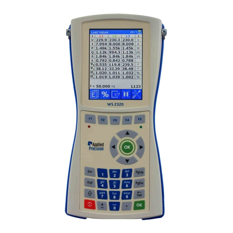
Applied Precision ISOMET 2114 User manual

ISOMET 2114
Thermal properties analyzer
User’s Guide
Version 1.46

ISOMET 2114
User’s Guide
www.appliedp.com
2
Contents
1. Safety Considerations and Instructions ............................................................................... 3
2. Introduction............................................................................................................................. 4
2.1 Description................................................................................................................................4
2.2 PRINCIPLE OF OPERATION...................................................................................................5
2.2.1 Measurement Probes........................................................................................................ 5
2.2.2 Accuracy Influencing Factors ............................................................................................ 5
2.3 Measuring System....................................................................................................................6
3. Measuring Unit........................................................................................................................ 7
3.1 Front panel................................................................................................................................7
3.2 Rear panel................................................................................................................................ 8
3.3 Bottom Connectors................................................................................................................... 9
3.4 Measurement Probes................................................................................................................ 9
3.4.1 Locking Mechanism......................................................................................................... 10
3.4.2 Cable Connecting............................................................................................................ 10
3.4.3 Cable Disconnecting........................................................................................................ 11
3.5 Power Supply.......................................................................................................................... 11
4. Operation............................................................................................................................... 13
4.1 Measurement.......................................................................................................................... 14
4.2 Results.................................................................................................................................... 16
4.3 Menu....................................................................................................................................... 17
4.3.1 Measurement Settings..................................................................................................... 18
4.3.2 Test Settings ................................................................................................................... 19
4.3.3 System Settings .............................................................................................................. 20
4.3.4 Information Screen.......................................................................................................... 21
4.3.5 Calibration....................................................................................................................... 22
5. Software data exchange....................................................................................................... 23
5.1 Software Installation................................................................................................................ 23
6. Quick reference for making the first measurement ........................................................... 28
Technical Specification................................................................................................................... 29
DECLARATION OF CONFORMITY.................................................................................................. 30

ISOMET2114
User’s Guide
www.appliedp.com
3
1. Safety Considerations and Instructions
Basic safety instructions
The unit is dedicated for hand-held operation with strictly limited conditions for connecting to
circuits with non-safe potential level referring to IEC EN 61010.
Keep the operational conditions defined in technical specification.
Using other than supplied power adapter is not allowed.
Operation of the power adapter is for indoor use only.
CAUTION !!
Exposing the measurement probe to increased thermal or mechanical stress can lead to its
damage or permanent deviation from specified accuracy.

ISOMET 2114
User’s Guide
www.appliedp.com
4
2. Introduction
2.1 Description
ISOMET Model 2114 - Thermal Properties Analyzer
Multifunction instrument for measurement of
Thermal conductivity () [ W m-1 K-1 ]
Thermal diffusivity (a) [ m2s-1]
Volume heat capacity (c) [ J m-3 K-1]
Temperature [ °C ]
ISOMET 2114 is a hand-held measuring instrument for direct measurement of heat transfer
properties of a wide range of isotropic materials including cellular insulating materials, plastics,
glasses and minerals. It is equipped with two types of measurement probes: needle probes for soft
materials, surface probes for hard materials. It applies a dynamic measurement method, which
enables reducing the measurement time in comparison with steady state measurement methods.
Built-in menu system on color graphic display and the alphanumeric keypad enable effective
interactive communication with the device. Measurement data are stored in the high capacity internal
memory. Content of the memory is accessible through the display or it can be transferred into a PC
by USB or RS-232 interface. Calibration data in internal memory ensure interchangeability of probes
without affecting the measurement accuracy. Since supplied measurement probes have good long
term stability through the whole measurement range, periodic calibration before measurements is not
necessary. Nevertheless, calibration by means of a reference material is supported by the instrument.
Calibration coefficient stated in the sense of the standard ASTM –5334-08 may be applied to
subsequent measurements automatically.
ISOMET2114 is powered by internal rechargeable batteries, which makes outdoor, in situ
measurements easier.
Applications
Civil Engineering
Measurement of thermal transfer properties of building materials and constructions
Optimization of development of thermal insulating materials
Geological Investigations
Indoor and outdoor measurement of thermal transfer properties of soils, sands, rocks, etc.
Optimization of development of thermal insulating materials
Chemical Industry
Measurement of heat transfer properties of chemical substances, agents, lubricant greases,
plastics, suspensions, foam, rubbers, etc.
Woodworking Industry
Measurement of heat transfer properties of woods
Moisture measurement and drying process optimization
Textile Industry
Optimization of textile thermal contact comfort
Textile composition and surface adjustment
Evaluation of floor plates and carpets

ISOMET2114
User’s Guide
www.appliedp.com
5
2.2 PRINCIPLE OF OPERATION
Measurement is based on analysis of the temperature response of the analyzed material to heat flow
impulses. Heat flow is excited by electrical heating of resistor heater inserted into the probe which is
in direct heat contact with the tested specimen. Evaluation of thermal conductivity and volume heat
capacity is based on periodically sampled temperature records as function of time, provided that heat
propagation occurs in unlimited medium.
2.2.1 Measurement Probes
The broad measurement range of the ISOMET allows to measure variety of materials with extremely
different mechanical properties. It is possible to measure solid materials ranging from soft foams to
hard rocks, liquids, suspensions etc. In order to obtain the best measurement accuracy on specific
materials two general probe types were developed:
a/ Needle probes
b/ Surface probes
Needle probes can be utilized for solid soft materials where it is possible simply to stick the needle of
the probe into the measured material or it is possible to bore precise aperture for the needle.
Measurement accuracy using the needle probes is not degraded even for the best low-conducting
polyurethan foams but it might be significantly affected in harder materials by inaccuracy of the
aperture. Expected minimal material thickness surrounding the needle probe is from 20 mm to 40 mm
depending on the material's thermal diffusivity (conductivity). The sensor part of the probe begins 15
mm from the probe tip and is 50 mm long. Needle part of the probe should be fully inserted into
measured material up to its handle in order to obtain the best measurement accuracy but 80 mm
insertion depth is acceptable in most cases.
Needle probes are calibrated without any thermal contact improving means for soft porous materials.
For hard solid non-porous materials where apertures for probe are bored silicon oil is used to fill the
hole.
Surface probes are intended to use for measurement on solid and hard materials. Flat surface of at
least 60 mm diameter is satisfactory for the probe. Demand for the accuracy of the surface flatness
increases with increasing thermal conductivity value of the tested material. The expected minimal
thickness of evaluated material is ranging from 20 mm to 40 mm depending on its diffusivity
(conductivity).
Surface probes, in principle, can be utilized also for extremely low conductive foams. However, the
properties of the surface layer of materials may significantly differ from the properties of the inner
structure (especially in case of low-conductive gas filled foams, due to filling gas diffusion).
Surface probes are calibrated without any thermal contact improving means.
2.2.2 Accuracy Influencing Factors
Measurement of thermophysical properties by ISOMET can be, like all other measurements,
influenced by conditions of measurement.
Following influencing factors might have the most significant effect on measurement:
Quality of the thermal contact of the measurement probe and measured object
Temperature fluctuations and drift
Finite dimensions of the measured material sample
Non-homogeneity of the measured material sample
Anisotropy of the measured material sample
Humidity of the measured material sample.

ISOMET 2114
User’s Guide
www.appliedp.com
6
2.3 Measuring System
Measuring system of ISOMET 2114 consists of Measuring Unit, optional Needle and Surface type
measurement probes supported with following accessories:
Standard Accessories
Optional Accessories
ISOMET 2114
Measuring Unit
IPN 1100
Needle Probe with one meas.
range
ISTC 2000
Transport Case
IPS 1100
Surface Probe with one
meas. range
WSPA 2000
Power Adapter (100-240V)
IPNR
Additional meas. range for
IPN 1100
CCU 1000
USB Communication Cable
IPSR
Additional meas. range for
IPS 1100
ISCD
CD-ROM with Manual and
Software
WSCA 1000
Car Outlet Adapter (12V)
SOB
Set of Borers for Needle
Probes

ISOMET2114
User’s Guide
www.appliedp.com
7
3. Measuring Unit
3.1 Front panel
Front panel of the device
1
Display
- colour graphical display
9
Function keys
- quick access to functions
2
LED
- indicates enabled heating
10
Indicator of charging batteries
- green LED indicating charging status
3
Alphanumeric keypad
- keys 0-9 (a-z)
11
Choice keys
- arrows and OK
4
ESC key
- termination of functions
12
PgUp key
- paging upwards
5
Exp key
- input of exponent of number
13
PgDn key
- paging downwards
6
Shift key
- switching of keys functionality
14
Del key
- deleting
7
Power key
- power on/off of the device
15
OK key
- confirmation of choice
8
Sign key
- input of plus/minus sign
16
Point key
- decimal point
1
9
14
2
10
4
5
7
6
8
11
12
13
15
16
3

ISOMET 2114
User’s Guide
www.appliedp.com
8
3.2 Rear panel
Back panel of the device
1
Protection Rubber
- blue protection rubber
2
Nameplate
- nameplate with serial number
3
Accumulators box
- box for accumulators (4 x AA)
4
Screws of accumulators box
5
Screws of back side of the device
1
2
3
4
5

ISOMET2114
User’s Guide
www.appliedp.com
9
3.3 Bottom Connectors
Bottom side connectors
1
USB Connector
- communication connector USB
2
RS-232 Connector
- communication connector RS-232
3
Power Connector
- connector of power adapter (+12V)
3.4 Measurement Probes
ISOMET 2114 is supplied with various types of measurement probes. Calibration coefficients and
further technical parameters are written into the probe nonvolatile memory, which ensure
interchangeability of probes. These parameters are uploaded into the measurement unit during
initialization procedure after switching the measuring unit on. Therefore the measurement probe has
to be connected to the measurement unit before it is switched on or initialization may be activated by
switching the measuring unit on once more. “Probe” socket for connecting measurement probes is
situated on the top of the instrument.
Measurement probes are equipped with plastic cylindrical push-pull connectors with definite and safe
locking mechanism for quick and easy connecting to the measuring unit.
Receptacle
(socket)
Plug
on the cable of the accessory
1
2
3

ISOMET 2114
User’s Guide
www.appliedp.com
10
3.4.1 Locking Mechanism
Pulling on the cable or on the back nut causes
the locking fingers to grip tighter into the groove
inside receptacle (socket). A separation is
virtually impossible.
Pulling on the outer plug housing disengages the
locking fingers from the receptacle groove and
the connector separates easily.
3.4.2 Cable Connecting
Connecting
Connected cable

ISOMET2114
User’s Guide
www.appliedp.com
11
3.4.3 Cable Disconnecting
Incorrect disconnecting
Correct disconnecting
3.5 Power Supply
ISOMET2114 is powered by 4 pieces of AA sized 1.2 V rechargeable batteries. Batteries are
installed under the plastic cover on the rear panel of the instrument.
External power adapter with range of input voltage from 100VAC to 240V, 50-60Hz is supplied for
recharging batteries.
Batteries should be recharged when measuring procedure for thermal measurements is not
activated. Supplied Power adapter may be connected to the instrument also during measurement
procedure to power electronic circuits of the instrument but power adapter may not supply sufficient
power for taking correct thermal measurement when batteries are discharged.
It is recommended to start series of thermal measurements with fully charged batteries.
Powering Status Indicator, icon located in upper right corner of the display, indicates connection to
power adapter or state of batteries when power adapter is not connected.
More precise way for checking the state of batteries is available under the item System Info in Main
menu. Battery Voltage lower than 4.8 V is not sufficient for taking thermal measurement. The system
aborts thermal measurement automatically, when battery voltage is lower than 4.8 V.

ISOMET 2114
User’s Guide
www.appliedp.com
12
Batteries Charger Status is indicated by means of the green LED, situated on the front panel
keyboard under key F5.
Batteries Charger Status LED has three statuses:
- no light ..................... power adapter (charger) not connected
- flashing .................... batteries are charging
- steady light ............... batteries charging has been stopped
Charging time of discharged batteries is approx. 4.5 hours.
CAUTION !!
Use power adapter supplied with the device only.
Rechargeable batteries need periodical recharge, storing discharged batteries can cause their
damage.
Power Adapter WSPA 2000

ISOMET2114
User’s Guide
www.appliedp.com
13
4. Operation
Measuring unit of ISOMET 2114 is equipped with color 3.5″ TFT LCD display, alpha-numeric
keyboard, USB and RS232 communication ports, which ensure its simple operation.
Switching on and switching off the device is done by pressing the red Power key for approx. 3
seconds. Pressing the Power key for shorter time toggles the display backlight only. The measuring
unit should be switched on with disconnected battery charger, USB connection and with connected
measurement probe. When the instrument is switched on, display backlight turns on and after
initializing procedures and loading parameters from connected probes, the Stand By page appears
on the display.
Stand By page like all other pages is divided into 3 zones:
Stand By page
1
Header
page name
time
keyboard mode
battery status
2
Info
- measured and calculated values, results, parameters etc.
3
Functions
- graphical presentation of active function keys F1 –F5,
various meaning of function keys is represented by
different graphical representation, of function keys.
1
3
2

ISOMET 2114
User’s Guide
www.appliedp.com
14
4.1 Measurement
After switching the measuring unit on and uploading parameters from the connected probe, Stand by
Page containing serial number of the connected probe is shown on the display.
After short initialization procedure, continuous temperature measurement is activated by means of
two temperature sensors installed in the measurement probe. Temperature values, signed as THTR
and TINT, are displayed with the slope of their time dependence qualifying the state of thermal
equilibrium around the probe.
Further data, measurement range of the connected probe and measurement label are edited in the
system menu.
Control keys on the Stand By page:
F1 ................................. start measurement
F4 ................................. review and deleting results
F5 ................................. switches to the system menu of the page where configuration of
measurement and the system can be performed
Function keys without graphical presentation are not active.
Loading parameters
Stand By page
Thermal conductivity measurement is started by pressing the key F1. After running thermal
conductivity measurement, Stand By page turns to the Measurement page.
Active function keys on the Measurement page:
F1 ............ serves for stopping thermal conductivity measurement. Pressing the key F1
displays request for stopping the measurement. The running measurement is
stopped after confirmation by the key F5.
F4 ............ displays results in the database
F5 ............ switches to the System Menu page, where configuration of measurement and the
system can be performed
Measurement page contains progress bar characterizing progress of the measurement time and
number of selected measurements with number of the measurement in progress.

ISOMET2114
User’s Guide
www.appliedp.com
15
Measurement page
Measurement STOP page
It is recommended to configure the instrument for repeated thermal conductivity measurement.
Results of completed thermal conductivity measurements are available any time also during
measurement in progress. Results page for reviewing results may be activated on Measurement,
Stand By or menu page by pressing the key F4. Pressing the key F4 on the Measurement or Stand
By page opens the results database at the last completed measurement. Activating the Results page
from Menu page opens the results database at the last reviewed result.
Control keys on the Measurement page:
ESC .............................. exit (return to previous page)
F1.................................. stop measurement
F2.................................. skip waiting for thermal equilibrium
F4.................................. review or deleting results
F5 ................................. System Menu

ISOMET 2114
User’s Guide
www.appliedp.com
16
4.2 Results
The database screens allow reviewing and deleting measurement results
Results page
Deleting result record
Control keys:
F2 ................................ switching to measurements of selected test
F5 ................................ deleting selected test results
▼▲ .............................. scrolling results
OK ............................... confirmation of selected item
ESC ............................. exit screen or close browsing table
Measurement results are organized in two levels. Repeated measurements on the same material are
regarded as one test (series of measurements). Arrow keys enable scrolling measurement results or
test results, which mean average values of measurement results taken as one series of
measurement. When test results are displayed, standard deviation of the average value is also
displayed. Pressing F2 enable entering into measurement results of the selected test. Returning to
test results from measurement results is possible by pressing the key F1.
Pressing the key F5 enables deleting the selected measurement or test result. Deleting has to be
confirmed by the key F3 or it may be discarded by means of the key F4.
Measurement results may be transferred into your PC by means of the supplied program
ResReadout_I2114.exe. Measurement results are transferred as text file with file extension “csv”
accepted by table processors.

ISOMET2114
User’s Guide
www.appliedp.com
17
4.3 Menu
Menu enables access to settings, database of measurement results, information about device and
device calibration. It can be activated by pressing the key F5 on Stand By page.
Menu page
Content:
1. Measurement Settings ............... measurement settings
2. Test Settings ............................... test settings
3. System Settings .......................... system settings
4. Results ........................................ review and deleting results
5. Info .............................................. gives information about the devices
6. Calibration .................................. enables measurement calibration
Control keys (active on Menu page):
F1 or 1 ......................................... measurement settings
F2 or 2 ......................................... test settings
F3 or 3 ......................................... system settings
F4 or 4 ......................................... database
F5 or 5 ......................................... info
6 ................................................... calibration
▼▲ ............................................... enable selecting the wished item
OK ................................................ confirmation of selected item
ESC .............................................. exit (return to previous page)

ISOMET 2114
User’s Guide
www.appliedp.com
18
4.3.1 Measurement Settings
Measurement Settings page enables selection of measurement range of connected probe with more
than one range.
Generally, data are entered into the system by means of combo boxes and edit boxes. First the
controlling element has to be selected by means of arrows on the keyboard. Selection of a control
element is signed by turning colors into their inverse color, white background into blue background
and blue letters into white letters. After pressing the OK key, selected control element becomes
editable, items of a combo box are scrollable and edit boxes rewritable.
For example, the combo box for selecting measurement range may become scrollable by pressing
arrow down once and pressing OK key. After that, possible measurement ranges of the connected
probe may be displayed in the combo box by pressing arrow keys. The selected measurement range
is confirmed by OK key. By pressing the functional key F4, the selected measurement range may be
stored into the memory of the measuring unit and after next initialization the stored measurement
range will be selected automatically.
Measurement Settings screen
Measurement Settings page also enables modification of Steady state condition for starting
measurement. After selection of edit box by pressing arrow and OK keys, the new value is entered
into the edit box. The wished value in the edit box is confirmed by pressing OK.
There are further informative data on the Measurement Settings page: Measurement Method,
Temperature Step and Max Temperature, which are not editable.
Control keys:
F1, ESC ....................... exit (return to previous page)
F3 ................................ load default (factory) settings
F4 ................................ save selection of the measurement range into memory

ISOMET2114
User’s Guide
www.appliedp.com
19
4.3.2 Test Settings
Test Settings page enables configuring number of repeated measurement, pause between
measurements and entering three measurement labels to identify the series of repeated
measurements.
Editing of edit boxes is described in section 4.3.1. When any of the edit boxes is selected, keyboard
mode may be modified for typing upper case letters or numbers by pressing the Shift key.
Test Settings screen
Control keys:
F1, ESC ........................ exit (return to previous page)
F4 ................................. save all changes into memory (will be loaded after next switch on)
F3.................................. loading factory settings

ISOMET 2114
User’s Guide
www.appliedp.com
20
4.3.3 System Settings
System Settings page contains general parameters of the system of the device.
Page is showed in two screens and switching between them is done by key F5.
System Settings screen 1/2
System Settings screen 2/2
Content:
Date ........................................ actual date
Time ........................................ actual time
Language ............................... selection of language of devices user interface
BAUDRATE ............................ settings of baud rate of device communication interfaces
RS-232 ......................... baud rate of RS-232 communication interface: 300, 600, 1200, 2400,
4800, 9600, 19200, 28800, 38400, 57600 or 112000
USB ............................. baud rate of USB communication interface: 300, 600, 1200, 2400,
4800, 9600, 19200, 28800, 38400, 57600 or 112000
BACKLIGHT ........................... settings of backlight of display
Intensity....................... backlight intensity: 10%, 20% … 90% or 100%
Auto off timeout ......... automatic backlight switch-off time: 1 / 2 / 5 / 10 / 20 / 30 min or
OFF (inactive)
POWER SUPPLY ................... settings of power supply
Auto off timeout ......... automatic power switch-off time: 1 / 2 / 5 / 10 / 20 / 30 min or 1 / 2 / 4
h or OFF (inactive)
SOUNDS ................................. settings of sounds
Keypad beep ............... acoustic indication of keys pressing: ON or OFF
End of meas. beep ..... acoustic indication when measurement is finished: ON or OFF
End of test beep ......... acoustic indication when test is finished: ON or OFF
Control keys:
F1, ESC ....................... exit (return to previous page)
F4 ................................ save all changes into memory (will be loaded after next switch on)
F5 ................................ switching between screens 1/2 and 2/2
Table of contents
Other Applied Precision Measuring Instrument manuals
Popular Measuring Instrument manuals by other brands

Siemens
Siemens 3NP11 3 Series operating instructions

SATO KEIRYOKI
SATO KEIRYOKI 7720-00 instruction manual

Siemens
Siemens SITRANS LR 300 Quick start manual

Veris
Veris H81xx installation guide

Airmar Technology Corporation
Airmar Technology Corporation UDST800 Owner's guide & installation instructions

tempmate
tempmate c1 user manual