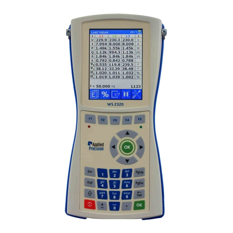
Applied Precision RS 2130 User manual

Reference Standard
Standard Meter of Electrical Power and Energy
Model
RS 2130
RS 2330
RS 1130
RS 1330
User’s Guide
Version: 9.1

Reference Standard RS 2x30, RS 1x30
User’s Guide
RS-UG91-EN www.appliedp.com
2
Content
1. Safety Considerations and Instructions......................................................................................4
2. Device Description........................................................................................................................ 5
2.1 Introduction...............................................................................................................................5
2.2 Front Panel and Rear Panel......................................................................................................6
2.3 Rear Panel Connectors and Clamps.........................................................................................7
2.4 Connecting of the Device..........................................................................................................8
3. Local Control................................................................................................................................. 9
3.1 Manual Control........................................................................................................................ 10
3.1.1 Menu Entering Keys........................................................................................................10
3.1.2 Menu Control Keys..........................................................................................................11
3.1.3 Parameter Value Editing Keys.........................................................................................11
3.1.4 Functional Key and Keys Combinations ..........................................................................11
3.2 Menu Description.................................................................................................................... 12
3.2.1 Main Menu.......................................................................................................................12
3.2.2 Measurement Menu......................................................................................................... 12
3.2.3 Special Functions Menu ..................................................................................................12
3.2.4 System Menu ..................................................................................................................13
3.2.5 Calibration Menu .............................................................................................................13
3.2.6 Calibration Menu „More Calib...“ ...................................................................................... 13
3.2.7 Range Menu....................................................................................................................14
3.2.8 Energy Menu...................................................................................................................14
3.2.9 Frequency Mode Menu....................................................................................................14
3.2.10 History Mode Menu .......................................................................................................15
3.2.11 Menu TALK ONLY.........................................................................................................15
3.2.12 Menu TALK ONLY COM1..............................................................................................15
3.2.13 Output Frequency Response Menu...............................................................................15
3.2.14 RS-232 Menu................................................................................................................16
3.2.15 Display Menu.................................................................................................................16
3.2.16 Keyboard Menu............................................................................................................. 16
3.2.17 Impulse Menu................................................................................................................ 16
3.2.18 Impulse Outputs Fout1 … Fout3 Menu .......................................................................... 17
3.2.19 Impulse Input Fin Menu.................................................................................................17
3.2.20 Frequency Input Configuration Menu.............................................................................17
3.2.21 OPS Measurement Mode Menu .................................................................................... 18
3.2.22 Dosage Menu................................................................................................................ 18
3.2.23 SI/SU Contacts Menu in Auto Mode .............................................................................. 18
3.2.24 Control Port Menu .........................................................................................................18
3.2.25 Quantities Menu ............................................................................................................19
3.2.26 Harmonic Graph Menu .................................................................................................. 19
3.2.27 Contrast Menu............................................................................................................... 19
3.2.28 Control Port Initialization Menu...................................................................................... 19
4. Remote Control........................................................................................................................... 20
4.1 Commands .............................................................................................................................20
4.1.1 General Commands ........................................................................................................20
4.1.2 Other Commands............................................................................................................ 20
5. Features and Functions.............................................................................................................. 21
5.1 System Time...........................................................................................................................21
5.2 Display.................................................................................................................................... 21
5.3 Keyboard ................................................................................................................................22
5.3.1 Keyboard Beep................................................................................................................22
5.3.2 Keyboard Lock ................................................................................................................22

Reference Standard RS 2x30, RS 1x30
User’s Guide
www.appliedp.com RS-UG91-EN
3
5.3.3 Keyboard Emulation.........................................................................................................22
5.4 Input / Output User Port (CONTROL PORT) ...........................................................................23
5.5 Serial Port (RS-232 PORT) .....................................................................................................24
5.6 Configuration & Calibration settings.........................................................................................24
5.7 Password ................................................................................................................................25
5.8 Autocalibration.........................................................................................................................25
5.9 Measurement ..........................................................................................................................26
5.9.1 Operation Modes .............................................................................................................26
5.9.2 Measuring Time Interval (Time Base) ..............................................................................26
5.9.3 Division Factor.................................................................................................................26
5.9.4 Extern Ratio.....................................................................................................................27
5.9.5 Ranges configuration.......................................................................................................27
5.9.6 Measurement data acquisition .........................................................................................27
5.9.7 Energy Accumulation.......................................................................................................29
5.10 Impulse Output......................................................................................................................30
5.11 Impulse Input.........................................................................................................................32
5.12 Impulse Quick Response mode.............................................................................................33
5.13 Harmonics.............................................................................................................................33
5.13.1 Harmonic Content..........................................................................................................33
5.13.2 Harmonic Limitation .......................................................................................................34
5.14 Vector Diagram .....................................................................................................................35
5.15 Meter Error Test and Meter Constant Test.............................................................................35
5.15.1 COM and OPS connectors.............................................................................................37
5.15.2 Remote interface commands .........................................................................................37
5.16 Measured Values History System..........................................................................................39
5.17 Mode 'TALK ONLY' ...............................................................................................................43
5.17.1 LONG format description ...............................................................................................43
5.17.2 SHORT format description.............................................................................................43
5.17.3 Commands ....................................................................................................................44
5.17.4 Quantities parameter......................................................................................................44
5.17.5 Quantities list .................................................................................................................45
5.18 Dosage..................................................................................................................................46
5.18.1 Dosage contacts SU/SI..................................................................................................46
5.18.2 Dosage cable AP Reference Standard –AP Power Source...........................................47
5.18.3 Preparation for dosage...................................................................................................47
5.18.4 Running of dosage.........................................................................................................47
5.18.5 Dosage Modes...............................................................................................................47
5.18.6 Controlling and configuring of dosage function...............................................................48
Appendix ..........................................................................................................................................51
Command Summary .....................................................................................................................52
Menu.............................................................................................................................................57

Reference Standard RS 2x30, RS 1x30
User’s Guide
RS-UG91-EN www.appliedp.com
4
1. Safety Considerations and Instructions
This unit has been designed and tested according to EN 61010 standard and has left the
manufacturer’s premises in a state fully complying the safety standards.
In order to maintain the unit in a safe state and to ensure safe operation, the following instructions must
be reviewed and fully understood before operation:
▪When the unit is to be permanently cabled, first connect an uninterruptible protective earth
ground conductor before making any other connection.
▪If the unit is to be connected to other equipment or accessories, prior to energizing any unit
verify that common ground exists between them.
▪Verify that the available mains voltage corresponds to specification of the unit.
▪The Safety Class I unit provided with disconnectible AC supply cable and plug may only be
operated from a power socket with protective earth ground connection.
▪Any interruption or loosening of the protective earth ground conductor either inside or outside
the unit or in an extension cable will cause a potential shock hazard that could result in personal
injury.
▪The protective earth ground conductor shall not be interrupted intentionally.
▪To avoid electrical shock do not remove protection or covers of the unit; refer to qualified AP
Service Center for maintenance of the unit.
▪For continued protection against hazard, replace the line fuse(s) only with the same type and
current rating.
▪Observe safety regulations and rules and also additional safety instructions whether specified
in manual for prevention of accidents.

Reference Standard RS 2x30, RS 1x30
User’s Guide
www.appliedp.com RS-UG91-EN
5
2. Device Description
2.1 Introduction
The Reference Standard is the single-phase (RS 2110) and three-phase (RS 2310) version of
precision meter for electrical power and energy measurement.
The Reference Standard is designed to meet all requirements put on a reference standard in a
single- and three-phase electricity meter testing and calibration systems. The Reference Standard can
be set to any real or artificial mode of operation in three phase system and is capable to evaluate the
individual quantities per phase and the three-phase cumulative quantities as well.
The Reference Standard is based on precision 24-bit A/D conversion and digital signal processing
technology enabling accurate evaluation of all main and informative quantities. Beyond measurement
of all kinds of power, voltage, current and phase, the meter measures the harmonic content and
distortion of the input signals.
The Reference Standard has independent input circuits for the individual phases. This feature in
combination with the possibility to assign the impulse output to any combination of the input channels
(phases) enablesfor example to use the device in one phase system while the free channels can gather
additional information like power consumption of the current and voltage circuits for contact error
monitoring.
The Reference Standard makes harmonic analyze of the voltage and current spectrum and
measures and computes these quantities shown in display of the device:
Quantity
Description
Code
Unit
Voltage
Effective value of the alternating voltage
U
V
Current
Effective value of the alternating current
I
A
Phase U
Phase offset between Uxand U1
φU
°
Phase I
Phase offset between U and I
φI
°
Frequency
Frequency
f
Hz
Power Factor
Power factor
Λ
-
Distortion of Voltage
Distortion of voltage
DFU
%
Distortion of Current
Distortion of current
DFI
%
Active Power
Active power
P
W
Reactive Power
Reactive power
Q
VAr
Apparent Power
Apparent power
S
VA
Phase-to-phase Voltage
Phase-to-phase voltage
Upp
V
Sum of Active Power
Sum of active powers in all channels
ΣP
W
Sum of Reactive Power
Sum of reactive powers in all channels
ΣQ
VAr
Sum of Apparent Power
Sum of apparent powers in all channels
ΣS
VA
Sum of square Voltage / 1
Sum of square voltage / 1 Ω
ΣsqrU/1Ω
W
Sum of square Current / 1
Sum of square current / 1 Ω
ΣsqrI/1Ω
W
Active Energy
Active Energy
Ep
kWh
Reactive Energy
Reactive Energy
Eq
kVArh
Apparent Energy
Apparent Energy
Es
kVAh
Impedance Module
Module of impedance
Z
Ω
Impedance Phase
Phase of impedance
φ
°
Impedance Real Part
Real part of impedance
R
Ω
Impedance Imaginar Part
Imaginar part of impedance
X
Ω
Net Factor
Net power factor
nΛ
-
Default configuration shows in main screen these quantities: P,U,I,f,φ,DFU,DFI

Reference Standard RS 2x30, RS 1x30
User’s Guide
RS-UG91-EN www.appliedp.com
6
2.2 Front Panel and Rear Panel
Front Panel of models RS 2x30
Front Panel of models RS 1x30
Rear Panel

Reference Standard RS 2x30, RS 1x30
User’s Guide
www.appliedp.com RS-UG91-EN
7
2.3 Rear Panel Connectors and Clamps
Mains - Power supply connection
GND - Ground for digital and analogue circuits
Case/Earth - Metal parts of the device case and the guard wire of the network socket
RS232 - Communication bus RS 232
COM - Communication bus RS 422 used when device works as slave
OPS - Communication bus RS 422 used when device works as master
Ext. - Analogue input and output signals
Control - Digital input and output signals
FOUT0 - Impulse output FOUT0
FOUT1 - Impulse output FOUT1
FOUT2 - Impulse output FOUT2
FOUT3 - Impulse output FOUT3
FIN - Impulse input
L1, L2, L3 - Three independent measurement channels
I - Current clamps
U - Voltage clamps
Lo - Reference voltage clamp
Hi - Active current clamp
In - Current input clamp
Out 120 A Max - Current output clamp for 120 A range
Out 5 A Max - Current output clamp for 5 A range *
*special version
Warning:
Connecting the clamp GND of the device to the power supply causes the risk of life and can lead
to the destruction of the device.
The clamp Lo and GND can be only connected in the case there's no mean of gaining of the
dangerous voltage on the Lo clamp.

Reference Standard RS 2x30, RS 1x30
User’s Guide
RS-UG91-EN www.appliedp.com
8
2.4 Connecting of the Device
The three phase version of the device is equipped with three independent channels L1, L2, L3. Each of
them has two inputs: Current input (CURRENT) and voltage input (VOLTAGE). The inputs are insulated
from each other; therefor its connection is arbitrary. The basic connection of the voltage and current
clamps (only for one channel) for indicating of positive power (energy) is shown on the
Figure 1.
The benefit of this connection is that its own input current of the voltage input of the device does not
load the current input of the device. The measurement error caused by the volt drop on the current
clamps is negligible due to use of electronically compensated current transformer in the current input.
Figure 1
The inner ground of the electronic circuits connected to the GND clamp is common for both analogue
and digital circuits. The input voltage clamps Lo and Hi are in a differential connection against the GND,
i.e. the device measures the voltage difference between the clamps Lo and Hi. Each of the Lo and Hi
clamps can be loaded by operating voltage up to 500V against the GND clamp.
The positive orientation of the voltage difference is defined as Uhi - ULo.
The positive orientation of the current is from the clamp In to the clamp Out.
The lowest error caused by the finite symmetry of the potential input circuits can be reached by
connecting the neutral wire (or the wire with the lowest voltage against the guard wire) to the Lo input
clamps and the phase wires to the Hi clamps. The inner ground of the device, that is GND clamp, is
connected to the safety ground i.e. to zero voltage.
When connecting the device as an independent measuring device without connecting of the
communication channels, there is no grounding connected from the outside power supply. In this case
it is appropriate to connect the inner ground with the lowest potential by connecting the GND clamp with
the Case/Earth clamp and thus to the guard wire in the socket outlet.
VOLTAGE
CURRENT
In Out
Lo
Hi
GND
CASE/EARTH
Earth
Neutral
Phase
Load

Reference Standard RS 2x30, RS 1x30
User’s Guide
www.appliedp.com RS-UG91-EN
9
3. Local Control
The device RS 2x30 can be controlled locally using its display and keyboard. The content of the display
and the way the device is controlled depends on the current mode of the device.
Device modes:
•basic mode
•menu mode
•graphical mode for displaying of harmonic parts
•OPS Measurement Mode
•special modes
The display in the basic mode shows values of measured and activated parameters. The way how the
information is displayed can be modified by the menu parameters. Each measured parameter can be
switched on or off for display. The maximum number of concurrently displayed measured parameters
on display is 7. When there are allowed to be displayed more than 7 measured parameters, there are
displayed on the top 7 measured parameters according to their priorities. To display the menu in the
basic mode press any key. For return to the basic mode quit the menu or the special mode you have
selected.
The menu mode is used to control the device from a cascade menu displayed on the screen of the
display. The measurement continues in the background while using menu mode. The only difference is
that the actual values of the measured parameters are not displayed to the user. The menu is used to
set parameters of the device and perform calibrations, tests etc. To display the menu in the basic mode
press any key.
The graphical mode for displaying harmonic parts can be activated only when the FFT signal
analyse module is attached. To enter this mode, press the DEL key in the basic mode. For return to the
basic mode press DEL, "ESC" or the OK key. This mode is designed for informative displaying of
amplitudes of the harmonic parts of measured voltages and currents. The bar on the right side of y-axis
is the amplitude of the 1st harmonic part. Next harmonic parts are displayed in the right direction. No. of
maximum frequency can be set in configuration menu. The background noise, if activated, is displayed
between the columns of the harmonic parts. Amplitudes of all of the harmonic parts are displayed in a
ratio scale related to first harmonic part. The amplitude of the first harmonic part is set to 1. All six
amplitudes of the input channels are displayed as three voltage/current pairs. Switching between the
displayed channels can be done pressing keys "LEFT" and "RIGHT". Change of the ratio scale on the
screen of the display can be done pressing the keys "UP" and "DOWN".
The OPS Measurement Mode is used to control Local Evaluation Unit OPS and measure error of
connected electricity meter. This mode can be selected from menu <Measurement / Energy / Impulse
/ OPS Meas> or with "EXP"keyfrom the basic mode.To close this mode, press "ESC" or "EXP" button.
The basic activities of the device are not suspended –device is measuring in background. Detailed
description of this mode is in chapter 5.9.1 Operation Modes.
Special modes include calibration modes, test mode etc. The basic activities of the device are
suspended in these modes and the whole device is dedicated to the specific mode. To enter a specific
special mode, use the menu device modes. The way the device is controlled while working in the special
mode fully depends on the mode. The instructions shown on the screen and the description of the
specific mode in the manual explain the activities in special mode.

Reference Standard RS 2x30, RS 1x30
User’s Guide
RS-UG91-EN www.appliedp.com
10
3.1 Manual Control
The menu is composed of a number of cascade levels. One of the levels is shown on the following
figure:
The name of the menu level is shown in the first row of the display (The top level is called MAIN MENU
and all the other levels have their names set according to their contents).
Items of the specific menu are shown in the rows below the menu label. The maximal number of items
shown in a single menu screen is determined by the number of function keys (F1, F2 ... F6) on the
keyboard of the device. Each menu item is labelled by the assigned function key, followed by the name
of the menu item and in the right part of the menu there is a possible value of the menu item.
Types of the menu items:
•submenu - the label ends with characters ... - by choosing this menu item you enter a lower level
of the menu. Selected submenus are protected by a password, what is typical for the calibration
submenu.
•command - the label ends with special characters and the right part of the menu lebel is empty - by
choosing this menu item a specific command is executed.
•parameter - the label doesn't end with special characters and the right part of the menu label
contains a value - choosing this item menu the current value of the specified parameter can be
changed.
3.1.1 Menu Entering Keys
If the device appears in a basic state, the menu can be entered using:
OK - enter the main level and first item highlighting
F1, F2... - enter the basic menu level with immediate item selection which
is attached to key used (i.e. in accordance with a type of the given item,
immediate switch to the lower level, or immediate execution of the instruction, or
immediate editing of the parameter value will happen, respectively),
1, 2... - enter intothe mainmenu level and item highlight with a given sequence number,
another key - enter into the main level and first item highlight.

Reference Standard RS 2x30, RS 1x30
User’s Guide
www.appliedp.com RS-UG91-EN
11
3.1.2 Menu Control Keys
DOWN - pointer shift of the actual highlight item down, if the pointer is set at the last item,
it will move to the first one,
UP - pointer shift of the actual highlight item up, if the pointer is set at the first item, it
will move to the last one,
ESC -skip fromthe menu mode to the basic device state without considering theactual
menu level,
LEFT and DEL -shift in a cascade menu structure one level up, in direction to the main menu; if
the main menu was the actual level than the skip out and return to the basic
device state will happen,
RIGHT and OK - actual (highlight) item selection
F1, F2... -item selection with used attached soft key
3.1.3 Parameter Value Editing Keys
By parameter type item selection, editing mode will start and a change of this parameter value can be
performed.
If the parameter value is optional (i.e. ON/OFF, ENABLED/DISABLED...), the options are offered with
the highlighted actual value, UP and DOWN keys can be used for other value selection and approved
using OK key or skip out without accepting change.
If the parameter value is of numeric type, the actual value is offered as start value of the editing mode.
The value is highlight what indicates the possibility of value editing (the first used key is UP, DOWN,
LEFT, RIGHT or BS respectively), delete (the first used key is DEL) or begin overwrite. Key functions
in editing mode are as follows:
•DOWN skip to the text end,
•UP skip to the text beginning,
•LEFT pointer shift one character left,
•RIGHT pointer shift one character right,
•OK new value acknowledgement and editing mode termination,
•ESC editing mode termination without changes acceptation,
•DEL delete the character before the pointer and move to left by one char position
•EXP entry of the exponent character
•FUNC no special meaning so far (for new FW versions)
•+/- entry of ‘-‘ character or overwrite of the character ‘-‘ by ‘+’ character
•‘.’ entry of ‘.’ character
•0,1,2 ... 9 entry of the given number
3.1.4 Functional Key and Keys Combinations
Functional key is:
- “Func” key in bottom line of front panel (in newer devices with 29 keys membrane keypad)
or
- red SHIFT key in bottom line of front panel (in older devices with 33 keys panel keypad)
Functional key can be used in key combinations.
In some key combinations as functional key works also key +/-.

Reference Standard RS 2x30, RS 1x30
User’s Guide
RS-UG91-EN www.appliedp.com
12
Immediate Display Contrast Change
In a basic mode (when actual values of measured quantities are displayed) it is possible to change the
display contrast (without necessity to enter the device menu) using the following keys combinations:
1. +/- (Func key) and UP ...contrast enhancement in large steps
2. +/- (Func key) and DOWN ...contrast decrease in large steps
3. +/- (Func key) and LEFT ...contrast enhancement in small steps
4. +/- (Func key) and RIGHT ...contrast decrease in small steps
Remark: Display contrast change using keys is not possible on old version devices where this can be
done only by using a small potentiometer placed on the front panel.
3.2 Menu Description
Structure of the device menu is shown in the Appendix
3.2.1 Main Menu
Measurement.... - measurement menu,
Special func. … - special functions menu,
System ... - settings menu,
Calibration... - calibration menu,
Save Config. - saving of configuration parametersfrom the memory on the FLASH disk. Values
of parameters saved on the disk remain unchanged after device is switched off.
Actual values set during operation of the device reside in RAM which is
destroyed, after the device switch off. After power on of the device values of
configuration parameters from the FLASH disk are loaded.
Def. Config. - loading of configuration parameter values preset by manufacturer. This can be
used after extensive altering of configuration and unexpected behavior of the
device
3.2.2 Measurement Menu
Input / Range... - Range menu,
Energy ... - Energy menu,
Frequency Mode ... - menu of output frequency settings,
Operation Mode - operation mode selection menu with regard of wires number and power type.
Available modes are described in chapter 5.9.1 Operation Modes.
Time Base - setting of Time Base value
Harm. Meas Mode - setting the number of harmonics, which will be measured –FUNDAMENTAL
ONLY, FIRST n HARMONICS, or ALL 63 HARMONICS,
Harm. Meas Limit - setting the limit number - N of harmonics, which will be measured and evaluated.
This parameter also influences the number N from menu item „Harm. Meas
Mode“. for the second option.
Note: If ALL 63 HARMONICS option was chosen in previous menu, then the
parameter in this menu is placed in parentheses which means that this option will
not be considered during measurements.
Appar. Meas Mode - setting the way of apparent power acquisition. There are two options –
MEASURED or FROM P&Q (by calculation from active and reactive power)
3.2.3 Special Functions Menu
Vector Diagram -> - displays the Vector Diagram i.e. phases of all 6 channels (3 x U, 3 x I)

Reference Standard RS 2x30, RS 1x30
User’s Guide
www.appliedp.com RS-UG91-EN
13
Harmonic Graph -> - graphic representation of harmonic content. There is a chart on the left and
by up and down arrows zooming is changed in range 1x - 20x. On the right
side there is a list of harmonic items where the 1st column from left (Harm)
means the number of harmonic item, 2nd column (U[%]) states for harmonic
item’s amplitude in % related to the fundamental harmonic and the 3rd column
(ph[°]) states for phase shift of harmonic item. Paging of this list is possible via
left and right arrows on the keypad.
History - Measured history values menu. This feature is described in chapter
5.16 Measured Values History System.
Talk Only … - settings of menu ‘TALK ONLY’. Parameter value STATE is OFF or ON for
disabling resp. enabling of this mode. Item „COM...“ sets this mode specifically
for this port in terms of its state, format and transferred quantities.
Fout Response … - setting theresponsesof impulse output. QUICKMODE –turning on the mode
of quick responses, parameter THRESHOLD holds the threshold value stated
in %.
Keyboard Test - launching of keypad test
3.2.4 System Menu
About - summary of basic device information: device type, device model, device serial
number, (device class), hardware version and firmware version.
RS-232... - RS 232 menu
Display.... - display menu
Keyboard … - keyboard menu contains items for the setting of short voice signal generation
by each operation of keys (BEEP) and settings of keypad locking feature. Keypad
locking has these options: LOCK@SWITCH ON for locking the keypad right after
each device switch on, LOCK PASSWORD for password change and LOCK
NOW ->.
Watchdog - parameter activating/deactivating the device watchdog. If it is allowed, then in
case of device freezing, the device is reset.
Date & Time - actual device date and time, this is possible to change by editing,
Control Port - user output-input port menu control,
Remark: If the keypad islocked, a small icon with a figure of key appears in the top of display. To unlock
the keypad enter the password and press OK.
3.2.5 Calibration Menu
More Calib... - maintenance calibration and calibration constants menu
This calibration menu is protected by a password –it is intended for change of
the device calibration constants or for the device calibration by the manufacturer
or other qualified person.
Per. Autocalib - parameter (ON) or (OFF) enabling or disabling automatic call of short device
selfcalibration
Autocalib - short device selfcalibration activation (lasts for approx. 10 sec.). The short
calibration calibrates input circuits of device against internal DC voltage
reference. This helps to suppress the influence of ambient temperature changes.
3.2.6 Calibration Menu „More Calib...“
Access to this menu is password protected.
Calib Funcs … - setting of calibration functions
Calib Const. … - setting of calibration constants

Reference Standard RS 2x30, RS 1x30
User’s Guide
RS-UG91-EN www.appliedp.com
14
Ext. Ratio … - setting the recalculation ratio of input values if the device (e.g. transformer)
connected to Reference Standard requires it
DSP method - setting of Digital Signal Processing method of calculation of signal amlitudes.
Parameter value is ‘Direct&FFT’ or ‘Only FFT’. Default setting is ‘Only FFT’.
Noise Filter - setting of Noise Filter. Parameter value is ON of OFF.
Password Change - calibration menu password change
Save Calib. - save of calibration constant values from the memory into the disk. Values saved
on the disk are independent on the device bias and thus remain unchanged after
device switch off. This is in contrary to actual values in the memory influencing
device functions, which are lost, after the device switch off. The device switch on
always loads values from the disk,
Load Def. Calib - loading of calibration parameters preset by the manufacturer.
3.2.7 Range Menu
Voltage Auto - parameter setting the state of automatic setting of the measured voltage range.
The parameter value is ON or OFF,
Voltage - parameter setting the voltage range which is used for the voltage measurement
if the automatic setting is switched-off,
Current Auto - parameter setting the state of automatic setting of the measured current range.
The parameter value is ON or OFF,
Current - parameter setting the current range which is used for the current measurement
if the automatic setting is switched-off,
Voltage Factor - parameter for input voltage ratio factor value.
The device indicates and uses the voltage value equal to product of the measured
voltage value and the voltage factor value. The voltage factor is used in case of
input voltage transformer.
Current Factor - parameter for input current ratio factor value. Device indicates and uses the
current value equal to product of the measured current value and the current
factor value.
3.2.8 Energy Menu
Impulse... - impulse output menu,
Dosage … - dosage function menu,
Start / Stop -> - Start or Stop of energy accumulation into dedicated registry,
Reset -> - deletion of registry, which store the accumulated energy values,
RESET Key - enabling or disabling the use of resetting (Func) key in basic mode. This key
resets the registry storing the accumulated energy values.
Energy Unit - setting the unit of energy measurement with two options –basic quantity per
second or “kilo-quantity” per hour. Energy quantities with power/energy type then
in basic mode will appear respectively in Ws, VArs and VAs or using the other
option in kWh, kVArh and kVAh.
3.2.9 Frequency Mode Menu
Freq Mode - setting of Frequency Mode either to option AUTOMATIC or to FIXED FREQ.
Option AUTOMATIC let the device automatically choose the channel, from which
input frequency is calculated.
Fixed Freq. - setting the fixed frequency value if the previous parameter is set to FIXED
FREQ. otherwise (AUTOMATIC) this value is not taken into account
Channel Mode - setting of channel from which input frequency is calculated in case that
parameter „Freq Mode“ is set to AUTOMATIC. There are four options –
AUTOMATIC, VOLTAGE, CURRENT and FIXED.

Reference Standard RS 2x30, RS 1x30
User’s Guide
www.appliedp.com RS-UG91-EN
15
Fixed Channel - channel selection for fixed mode –one of 6 options (combinations L1 –L3 and
voltage, current). However, the previous parameter „Channel Mode” has to be
set to FIXED.
Remark: If the value is placed in parentheses, it is not considered, because the superior parameter is
most likely set into AUTO option.
3.2.10 History Mode Menu
Show History -> - display of historical statistics
State - enabling or disabling the History function
Quantities - without the possibility of any change (all quantities)
Integr. Time - integration time is always equal to the value of TIME BASE, which is set in
Measurement Menu. INTEGR. TIME item does not allow to change its value.
Reset - resetting the History records
3.2.11 Menu TALK ONLY
State - enabling or disabling TALK ONLY Mode, which serves to continuous sending
of measured data to communication port
COM1 ... - to enter the settings of COM1 port in order to get more options of TALK ONLY
Mode
3.2.12 Menu TALK ONLY COM1
State - enabling or disabling TALK ONLY Mode on COM1 port
Format - sent data format setting either to SHORT or LONG
Quantities ... - to enter the list of quantities where every single available quantity can be
selected in order to continuously send their values via COM1 port
3.2.13 Output Frequency Response Menu
Quick Mode - enabling or disabling the Quick Response Mode
Threshold - setting the threshold value in %

Reference Standard RS 2x30, RS 1x30
User’s Guide
RS-UG91-EN www.appliedp.com
16
3.2.14 RS-232 Menu
Baud Rate - parameter setting the RS-232 serial line communication rate set value in bauds.
The value of the parameter is 4800, 9600, 19200, 38400, 57600 or 115200
bauds, respectively,
Data bits - parameter setting the number of data bits set value on the RS-232 serial line.
The parameter value is 7 or 8, respectively,
Parity - parameter setting the RS-232 serial line set value. The parameter value is
“ODD” for the odd parity, EVEN for the even parity and NO for the no parity,
respectively,
Stop bits - parameter setting the number of stop bits set value on the RS-232 serial line.
The parameter value is 1 or 2, respectively,
3.2.15 Display Menu
Quantities... - quantities menu
Display - parameter setting the state of measured results values appeared onthe display.
The value of the parameter is ON or OFF for the switched-on or switched-off
results depicting on the display, respectively. Parameter is not related to the
device menu depicting, which is displayed always if it is activated,
Resolution - resolution setting: STANDARD = results with standard number of decimal digits
according to the shown variable type; HIGH –number of decimal digits is raised
by 1 comparing to option STANDARD; MAXIMAL - number of decimal digits is
raised by 2 comparing to option STANDARD.
Service Info - enabling or disabling (ON / OFF) of service information
Large Font - parameter setting the state when measured quantity is displayed in large font.
The option is activated if only one quantity is chosen to be displayed,
Harm. Graph... - harmonic items graph menu
Contrast... - display contrast change menu
VGA Output - parameter Disables or Enables VGA output on the rear side of newer devices
3.2.16 Keyboard Menu
Beep - enabling or disabling the beep functionality of the keyboard,
Lock@SwitchOn - enabling or disabling the automatic keypad lock right after each device switch
on
Lock Password - keypad unlocking password change
Lock Now -> - instant keypad lock with a basic mode activation.
3.2.17 Impulse Menu
FoutX Config. ... - four similar items (where X = 0,1,2,3) for four impulse outputs of the device.
Each one represents an access into submenu containing settings of particular
impulse output.
Fin Meas/Test ... - Frequency Input menu
OPS Meas/Test ... - OPS Measurement Mode menu

Reference Standard RS 2x30, RS 1x30
User’s Guide
www.appliedp.com RS-UG91-EN
17
3.2.18 Impulse Outputs Fout1 … Fout3 Menu
Output State - parameter setting the state of the device impulse output, which enables
frequency generation proportional to the measured power. The parameter value
is ACTIVE ENERGY for the frequency generation proportional to the measured
active power, REACTIVE ENERGY for the frequency generation proportional to
the measured reactive power, APPARENT ENERGY for the frequency
generation proportional to the measured apparent power, FIXED for constant
frequency generation and OFF for impulse output switched-off, respectively.
Channel Lx -parameter setting the selection of individual channels (L1, L2 or L3) for impulse
output functions. The value of the parameter is ON or OFF for the switched-on or
switched-off selection of the appropriate channel, respectively.
Fixed freq. - frequency value on the device impulse output in case that “State” parameter is
in the state “FIXED”.
Energy Factor -parameter setting the device impulse output multiplicity constant if the parameter
“State” is in the state ACTIVE ENERGY, REACTIVE ENERGY or APPARENT
ENERGY, respectively. Generatedfrequency is proportional tothe product of this
constant and sum of measured values of the given type of power in the selected
channels. These channels are given in “Channel Lx” parameters placed in the
Energy menu. Unit of showed value is in 1/Ws (1/Vas, 1/Vars) or 1/kWh (1/kVAh,
1/kVArh) and depends on values of Energy Factor and Factor Unit parameters.
Energy F. Unit - parameter setting the unit in which the value of parameter Energy Factor is
showed. Parameter is 1/Ws (1/Vas, 1/Vars) or 1/kWh (1/kVAh, 1/kVArh).
3.2.19 Impulse Input Fin Menu
Fin Meas/Test -> - start of Frequency Input screen (measurement is started immediately)
Fin Config … - Frequency Input Configuration menu
MUT Constant - parameter setting the constant of Meter Under Test
MUT Const. Unit - parameter setting the unit in which the value of parameter MUT Constant is
showed. Parameter is 1/Ws (1/Vas, 1/Vars) or 1/kWh (1/kVAh, 1/kVArh).
Int. Time - parameter setting the integration time for Fin measurement
3.2.20 Frequency Input Configuration Menu
Input State - parameter setting the state of the device frequency input which is proportional
to some type of measured power. The parameter value is ACTIVE ENERGY for
the frequency input proportional to the measured active power, REACTIVE
ENERGY for the frequency input proportional to the measured reactive power or
APPARENT ENERGY for the frequency input proportional to the measured
apparent power, respectively.
Channel Lx - parameter setting the selection of individual channels (L1, L2 or L3) for impulse
input functionality. The value of the parameter is ON or OFF for the switched-on
or switched-off selection of the appropriate channel, respectively.

Reference Standard RS 2x30, RS 1x30
User’s Guide
RS-UG91-EN www.appliedp.com
18
3.2.21 OPS Measurement Mode Menu
OPS Meas/Test -> - start of OPS Measurement Mode screen
Fout0 Config … - Impulse Output Fout0 Menu (this functionality is dependent on Fout0 settings)
MUT Constant - parameter setting the constant of Meter Under Test
Sample Type - parameter setting the mode of operation of OPS Measurement Mode.
Parameter value is ‘Impulses’ or ‘Int. Time’.
Int. Time - parameter setting the Integration Time for OPS Measurement Mode
No. of Impulses - parameter setting the Number of Impulses for OPS Measurement Mode
No. of Samples - parameter setting the Number of Samples for OPS Measurement Mode
3.2.22 Dosage Menu
Start - dosage instant start
Stop - dosage instant stop
Mode - setting of dosage function in respect of a type –TIME, ACTIVE ENERGY,
REACTIVE ENERGY or APPARENT ENERGY, SQUARE VOLTAGE, SQUARE
CURRENT, OFF,
Time - setting the dosage lasting for time dosage, stated in seconds,
Energy - setting the dosage amount for energy type dosage,
Energy Unit - setting the unit of energy when energy dosage is set,
Contact SI Mode - setting the SI contact into the state CONTACT OPEN or CONTACT CLOSED
or AUTO,
Contact SU Mode - setting the SU contact into the state CONTACT OPEN or CONTACT CLOSED
or AUTO,
Contact SI Auto ... - entry to Contact SI Auto Mode Menu,
Contact SU Auto ... - entry to Contact SU Auto Mode Menu,
Contact SI State - setting the SI contact state –open or closed,
Contact SU State - setting the SU contact state –open or closed,
3.2.23 SI/SU Contacts Menu in Auto Mode
Start State - setting the SI/SU contact state for dosage start, there are three options –OPEN,
CLOSED and UNCHANGED,
Start Delay - setting the delay of dosage starting, stated in seconds
Stop State - setting the SI/SU contact state for dosage stop, there are three options –OPEN,
CLOSED and UNCHANGED,
Stop Delay - setting the delay of dosage stopping, stated in seconds
3.2.24 Control Port Menu
Signal OUTx - parameter of the direct control of the appropriate bite at the user control port
(value LOW corresponds to the logical 0, and value HIGH to logical 1,
respectively),
Signal Inx - parameter (which can be changed) setting the actual state of appropriate bites
at the user control port (value LOW corresponds to the logical 0, and value HIGH
to logical 1, respectively),
Init values... - control port initializing menu,

Reference Standard RS 2x30, RS 1x30
User’s Guide
www.appliedp.com RS-UG91-EN
19
3.2.25 Quantities Menu
This menu contains list of quantities which device measures or calculates from themeasured quantities.
Displaying of selected quantities may be switched-on (ON) or switched-off (OFF). Up to seven
quantities can be displayed simultaneously. In case that only one quantity is chosen, the Large font
parameter, which determines if measured quantities are displayed in capitals or small fonts, is applied.
3.2.26 Harmonic Graph Menu
Harm. graph - parameter enabling (ENABLED) or banning (DISABLED) harmonic items of
measured signals graph displaying, if the FFT module of signal analysis is
present,
Background - parameter switching-on (ON) or switching-off (OFF) displaying of the noise
background in the graph of harmonic items of measured signals,
Max. freq. - parameter setting the maximal frequency displayed in the graph of harmonic
items of measured signals
3.2.27 Contrast Menu
Increase (+) - display contrast increase
Decrease (-) - display contrast decrease
Store - display contrast value storage into the device memory
3.2.28 Control Port Initialization Menu
Signal OUTx - parameter setting the initialization value (set after the device switch on) on the
appropriate bite of the user control port (value LOW corresponds to the logical 0,
and value HIGH to logical 1, respectively)

Reference Standard RS 2x30, RS 1x30
User’s Guide
RS-UG91-EN www.appliedp.com
20
4. Remote Control
Device control and measured values collection may be performed via remote control using RS-232
interface. RS-232 parameters can be configured from the front panel in the menu. Communication is
performed using device commands created in accordance with agreements of the SCPI standard
(Standard Commands for Programmable Instruments). The most importantagreements of this standard
are:
•parentheses { } restrict parameter in the command strain
•parentheses [ ] restrict optional parameters or parts of commands
•parentheses < > restrict parameter, which is due to be replaced by the value
•perpendicular line ( | ) separate options, from which exactly one has to be chosen
•introductory parts of words in the command strain in capitals are obligatory and small fonts at the
end of words are optional ( command SYSTem:VERSion? is identical with SYST:VERS? but
command SYSTe:VERSi? is not allowed )
•letters size in the command is optional ( command SYST:VERS? is identical with sYsT:VeRs? )
4.1 Commands
Summary list of commands is available in the Appendix
4.1.1 General Commands
*IDN?
Request for the device identification string (with the maximal length of 35 characters).
*RST
Device reset.
SYSTem:ERRor?
Request for the error announcement from the error announcement register. This register is a FIFO type
(=first in first out). Its capacity is 20 errors announcement with 80 characters to be the maximal length
of error announcement.
SYSTem:VERSion?
Request for the device firmware version.
SYSTem:HWVersion?
Request for the device hardware version.
SYSTem:CLASs?
Request for the device class.
SYSTem:SERNumb?
Request for the device serial number.
4.1.2 Other Commands
All other commands are function specific and are described in Functions and Features chapter.
This manual suits for next models
3
Table of contents
Other Applied Precision Measuring Instrument manuals