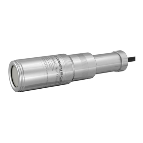
BD Sensors KL 1 User manual

www.bdsensors.com
D
E
EN
Deutsch
Montageanleitung /
Mounting instructions
Klemmengehäuse / Terminal Box
KL 1, KL 2
Zentrale
Headquarters
BD SENSORS GmbH
BD-Sensors-Str. 1
D - 95199 Thierstein
Deutschland / Germany
Tel.: +49 (0) 92 35 / 98 11-0
Fax: +49 (0) 92 35 / 98 11-11
Osteuropa /
Eastern Europe
BD SENSORS s.r.o.
Hradištská 817
CZ - 687 08 Buchlovice
Tschechische Republik /
Czech Republic
Tel.: +42 (0) 5 72 / 4 11-0 11
Fax: +42 (0) 5 72 / 4 11-4 97
Russland /
Russia
BD SENSORS RUS
39a, Varshavskoe shosse
RU - Moscow 117105
Russland /
Russia
Tel.: +7 (0) 9 59 81 / 09 63
Fax: +7 (0) 9 57 95 / 07 21
Diese Montageanleitung stellt einen Auszug
aus der ausführlichen Betriebsanleitung dar.
Bitte laden Sie sich diese auf unserer Home-
page herunter, falls Sie nicht mit dem Produkt
vertraut sind.
These mounting instructions are an excerpt from the complete
operating manual. It may be downloaded from our homepage, if
you are not familiar with the device.
http://www.bdsensors.de
http://www.bdsensors.com
– Technische Änderungen vorbehalten –
– Technical modifications reserved –
WARNUNG! Um Gefährdungen des Bedienpersonals und
Schäden am Gerät auszuschließen, müssen die beschri
benen Arbeiten von qualifiziertem Fachpersonal durchg
führt werden.
WARNUNG!
Halten Sie sich an Sicherheitshin
Handlungsanw
eisungen, die in d
geführt werden. Zusätzlich sind die geltenden Unfall
verhütungsvorschriften, Sicherheitsbestimmungen sowie
landesspezifische
Installationsstandards und die anerkan
ten Regeln der Technik einzu
Haftungsbeschränkung
Bei Nichtbeachtung der Betriebsanleitung, unsachgemäßer
Verwendung, Veränderung oder Beschädigung des Ger
tes übernimmt der Hersteller keine Haftung.
Bestimmungsgemäße Verwendung
Stellen Sie
sicher, dass das M
berührten Teilen verträglich
schränkt für die Anwendung geeignet
Datenblatt aufgeführten technischen Daten sind verbin
lich.
Produktidentifikation
Anschlussschaltbilder
KL 1
KL 2
Verwenden Sie für den ele
se eine abgeschirmte und verdrillte Mehraderleitung.
Bei der Installation müssen die Schutzleiter aller Kompo
nenten angeschlossen werden!
Die Versorgungsspannung U
sen des angeschlossenen Transmitte
optional für KL 2 /
optionally for KL 2:
Typen-
bezeichnung
Bestellcode
HART
®
Interface
Versorgung+
KL 2
mit
HART
®
Versorgung
KL 1
WARNUNG! Um Gefährdungen des Bedienpersonals und
Schäden am Gerät auszuschließen, müssen die beschri
e-
benen Arbeiten von qualifiziertem Fachpersonal durchg
e-
Halten Sie sich an Sicherheitshin
weise und
eisungen, die in d
er Betriebsanleitung auf-
geführt werden. Zusätzlich sind die geltenden Unfall
-
verhütungsvorschriften, Sicherheitsbestimmungen sowie
Installationsstandards und die anerkan
n-
ten Regeln der Technik einzu
halten.
Bei Nichtbeachtung der Betriebsanleitung, unsachgemäßer
Verwendung, Veränderung oder Beschädigung des Ger
ä-
tes übernimmt der Hersteller keine Haftung.
Bestimmungsgemäße Verwendung
sicher, dass das M
essmedium mit den medien-
berührten Teilen verträglich
und das Gerät uneinge-
schränkt für die Anwendung geeignet
ist. Die im aktuellen
Datenblatt aufgeführten technischen Daten sind verbin
d-
Verwenden Sie für den ele
ktrischen Anschluss vorzugswei-
se eine abgeschirmte und verdrillte Mehraderleitung.
Bei der Installation müssen die Schutzleiter aller Kompo
-
nenten angeschlossen werden!
Die Versorgungsspannung U
B
muss nach den Erfordernis-
sen des angeschlossenen Transmitte
rs ausgewählt werden.
Montage
Anschlussbelegungstabelle
WARNUNG!
Montieren Sie das Gerät immer im stromlosen Zustand!
KL 1
Serien-
Bestellcode
nummer
PC
RS 232 C
Versorgung+
Versorgung
-
U
B
Bezeichnung
(von links) Klemmenblock
Elektrische Anschlüsse
(Kabelfarben bei BD
Messumformern)
GND SENSOR
Erdungsklemme (
VS- SENSOR
Versorgung
VS+ SENSOR
Versorgung + (
GND SUPPLY
Erdungsklemme
VS+ SUPPLY
Versor
VS- SUPPLY
Versorgung
IN+ TRANSMITTER
Versorgung + (
IN- TRANSMITTER
Versorgung
GND TRANSMITTER
Erdungsklemme
IN+ SUPPLY
Versorgung +
IN- SUPPLY Ver
sorgung
GND SUPPLY
Erdungsklemme
HART HART (optional)
Weitere wichtige Informationen entnehmen
Sie bitte der ausführlic
Die Gehäusetiefe
beträgt 58 mm.
Außenerdung 4 mm²
Befestigungsbohrung
Druckausgleichs-
element
Kabelverschraubung
M16x1,5
(Kabel Ø5 ... 10 mm)
Montieren Sie das Gerät immer im stromlosen Zustand!
KL 2
Elektrische Anschlüsse
(Kabelfarben bei BD
SENSORS
Messumformern)
zu verbinden mit
KL 1
Erdungsklemme (
gn/ye, grün / gelb )
Schirm des Transmitters
Versorgung
- (bn, braun) negativer Anschlussleitung des Transmitters
Versorgung + (
wh, weiß) positiver Anschlussleitung des Transmitters
Erdungsklemme
Schirm der Versorgungsleitung
Versor
gung + positiver Signalleitung für Drucksignal
Versorgung
- negativer Signalleitung für Drucksignal
KL 2
Versorgung + (
wh, weiß) positiver Anschlussleitung des Transmitters
Versorgung
- (bn, braun) negativer Anschlussleitung des Transmitters
Erdungsklemme
(gn/ye, grün / gelb)
Schirm des Transmitters
Versorgung +
positiver Signalleitung für Drucksignal
sorgung
- negativer Signalleitung für Drucksignal
Erdungsklemme
Schirm der Versorgungsleitung sowie bei Überspan-
nungsschutz mit Massivleiter
- HART
-Modem
Sie bitte der ausführlic
hen Bedienungsanleitung.
Die Gehäusetiefe
beträgt 58 mm.
Die Gehäusetiefe
beträgt 55 mm.
Befestigungsbohrung
HA_
ON
HART
Befestigungs-
bohrungen ∅4,2
Kabelverschraubung
M16x1,5
(Kabel Ø5 ... 10 mm)
Druckausgleichs-
element

Englisch
www.bdsensors.com
D
E
EN
Montageanleitung /
Mounting instructions
Klemmengehäuse / Terminal Box
KL 1, KL 2
Zentrale
Headquarters
BD SENSORS GmbH
BD-Sensors-Str. 1
D - 95199 Thierstein
Deutschland / Germany
Tel.: +49 (0) 92 35 / 98 11-0
Fax: +49 (0) 92 35 / 98 11-11
Osteuropa /
Eastern Europe
BD SENSORS s.r.o.
Hradištská 817
CZ - 687 08 Buchlovice
Tschechische Republik /
Czech Republic
Tel.: +42 (0) 5 72 / 4 11-0 11
Fax: +42 (0) 5 72 / 4 11-4 97
Russland /
Russia
BD SENSORS RUS
39a, Varshavskoe shosse
RU - Moscow 117105
Russland /
Russia
Tel.: +7 (0) 9 59 81 / 09 63
Fax: +7 (0) 9 57 95 / 07 21
Diese Montageanleitung stellt einen Auszug
aus der ausführlichen Betriebsanleitung dar.
Bitte laden Sie sich diese auf unserer Home-
page herunter, falls Sie nicht mit dem Produkt
vertraut sind.
These mounting instructions are an excerpt from the complete
operating manual. It may be downloaded from our homepage, if
you are not familiar with the device.
http://www.bdsensors.de
http://www.bdsensors.com
– Technische Änderungen vorbehalten –
– Technical modifications reserved –
WARNING! In order to avoid hazards to operators and
damages to the device, the following instructions have to
be performed by qual
ified technical personnel.
WARNING! Adhere to the safety and operating instructions
stated in the operation manual. Effective regulations on o
cupational safety, accident prevention as well as national
installation standards and approved engineering tec
ni
ques must in addition be complied with.
Limitation of liability
If the instructions in the operating manual are not adhered
to or if the device is inappropriately used, modified or da
aged, liability is not assumed and warranty claims will be
excluded.
Intended use
Ensure that the medium is compatible with the media
wetted parts and that the device is suitable for the applic
tion without restrictions. The technical data listed in the cu
rent data sheet is binding.
Product identification
Wiring diagrams
KL 1
KL 2
For the electrical connection a shielded and twisted
multicore cable is recommended
The ground wires of all components have to be connected
when installing!
The supply V
S
has to be chosen according to needs of the
used transmitter.
Type
designation
Ordering code
optional für KL 2 /
optionally for KL 2:
KL 1
HART
®
Interface
supply
supply
KL 2
with
HART
®
WARNING! In order to avoid hazards to operators and
damages to the device, the following instructions have to
ified technical personnel.
WARNING! Adhere to the safety and operating instructions
stated in the operation manual. Effective regulations on o
c-
cupational safety, accident prevention as well as national
installation standards and approved engineering tec
h-
ques must in addition be complied with.
If the instructions in the operating manual are not adhered
to or if the device is inappropriately used, modified or da
m-
aged, liability is not assumed and warranty claims will be
Ensure that the medium is compatible with the media
-
wetted parts and that the device is suitable for the applic
a-
tion without restrictions. The technical data listed in the cu
r-
rent data sheet is binding.
For the electrical connection a shielded and twisted
multicore cable is recommended
.
The ground wires of all components have to be connected
has to be chosen according to needs of the
Mounting
Pin configuration
Designation
(from left) Terminal block
Electrical connection
(cable colours of BD SENSORS
transmitters)
GND SENSOR ground clamp (
gn/ye, green
VS- SENSOR
supply
VS+ SENSOR
supply +
GND SUPPLY
ground clamp
VS+ SUPPLY
supply +
VS- SUPPLY
supply
IN+ TRANSMITTER
supply + (
IN- TRANSMITTER
supply
GND TRANSMITTER ground clamp (
gn/ye, green
IN+ SUPPLY
supply +
IN- SUPPLY
supply
GND SUPPLY
ground clamp
HART HART (optional)
For more information, please read the detailed operating manual
Serial-
Ordering code
number
height of
housing: 58 mm.
PC
RS 232 C
supply
+
supply
- V
S
WARNING! Install the device only in currentless state!
KL 1
mounting
hole
ground
4 mm²
cable gland
M16x1.5
(cable Ø5 ... 10 mm)
pressure
balance item
housing depth
58 mm.
MA_KL_160118
Electrical connection
(cable colours of BD SENSORS
transmitters)
to connected with
KL 1
gn/ye, green
/ yellow) cable shield of transmitter
- (bn, brown) negative connecting cable of transmitter
supply +
(wh, white) positive connecting cable of transmitter
ground clamp
cable shield of supply line
supply +
positive signal line for pressure signal
supply
- negative signal line for pressure signal
KL 2
supply + (
wh, white) positive connecting cable of transmitter
- (bn, brown) negative connecting cable of transmitter
gn/ye, green
/ yellow) cable shield of transmitter
supply +
positive signal line for pressure signal
supply
- negative signal line for pressure signal
ground clamp
cable shield of supply line and solid wire (with
overvoltage protection)
- HART
-modem
For more information, please read the detailed operating manual
!
housing: 58 mm.
height of
housing: 55 mm.
KL 2
hole
housing depth
58 mm.
housing depth
55 mm.
cable gland
M16x1.5
(
cable
Ø
5 ... 10 mm
)
pressure
balance item
mounting hole
∅
4,2
HA_
ON
HART
This manual suits for next models
1
Table of contents
Languages:
Other BD Sensors Measuring Instrument manuals
BD Sensors
BD Sensors DM01 User manual

BD Sensors
BD Sensors LMK 457 User manual

BD Sensors
BD Sensors DMK 456 User manual

BD Sensors
BD Sensors LMK 457 User manual

BD Sensors
BD Sensors BD SIMEX PAC-73S User manual

BD Sensors
BD Sensors LMK 306 User manual

BD Sensors
BD Sensors BAROLI 02 User manual

BD Sensors
BD Sensors PCB+ User manual

BD Sensors
BD Sensors BD SIMEX PAD-73S User manual

BD Sensors
BD Sensors LMK 306 User manual