Page 1
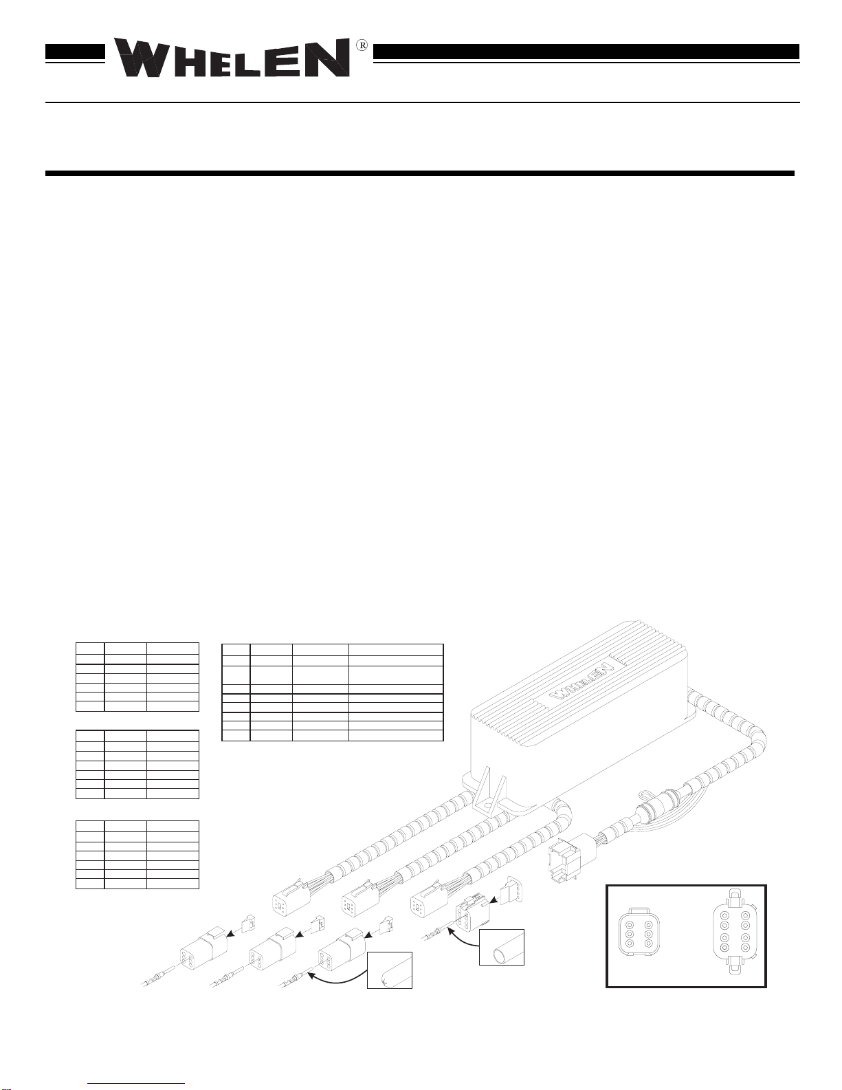
Plug #1(L1 & L2)
Plug #2(L3 & L4)
Plug #3(L5 & L6)
Receptacles
Wedges
Faceplate
Input Control Plug
Input Control Receptacle
Input Harness fuse
NOTE: Lamps L1, L3 & L5, alternate
with Lamps L2, L4 & L6.
Pin
Terminal
Socket
Terminal
Rear View
6-Conductor 8-Conductor
1
2
34
5
6
DEUTSCH
DEUTSCH
56 78
12 34
WPPSC694 Strobe Power Supply
Installation Guide
ENGINEERING COMPANY INC.
ROUTE 145, WINTHROP ROAD
CHESTER, CONNECTICUT 06412-0684
TELEPHONE: (860) 526-9504
FAX: (860) 526-4078
WARNING: The Strobe Light Power Supply is a high voltage device. Do not
touch or remove tube assembly in strobe light head assemblies while in
operation. Wait 10 minutes after disconnecting the unit from its power source
before starting work or troubleshooting on power supply or system.
Mounting your WPPSC694...
Caution: As it will be necessary to drill holes into the mounting surface, the
installer MUST be sure that no vehicle components or other vital parts could
be damaged by the drilling process. Check both sides of the mounting surface
before drilling begins!
1. Position the WPPSC694 in its proposed mountin
location to ensure that it fits
properl
. With the WPPSC694 in place, insert an awl or other suitable tool into the
mountin
screw area of the power suppl
and scribe the areas that are to be
drilled.
2. Remove the WPPSC694 from its mountin
area and, usin
an appropriatel
sized
drill bit, drill a hole in each of the areas scribed in the previous step.
3. Return the WPPSC694 to its mountin
location and usin
appropriatel
sized
hardware, secure the WPPSC694 to its mountin
surface.
Wiring your WPPSC694...
1. Locate the 8 position Input Harness Plug and connect as indicated in Fi
. 1.
Extend the BLACK and RED wires from the Input Harness Plug towards the
batter
.
2. Connect the RED wire to a fuse block (customer supplied) and then to the
POSITIVE terminal on the batter
.
NOTE! Although a 7.5 amp fuse (customer supplied) is required to be used in
the fuse block, do not install the fuse until
all
of the wire connections are
completed.
3. Connect the BLACK wire to the factor
chassis
round
ad
acent to the batter
.
Important!!!
The Deutsch water-proof connector will not function properly unless it is
connected exactly as the manufacturer intended. A Deutsch crimping tool
(Whelen p/n 66T0516435119C) is required for proper terminal crimping and
should be used whenever possible. Whelen Engineering does not recognize
the use of a non-Deutsch crimping tool, therefore any resulting damage would
void the warranty.
Assembly...
1. Locate the 3-conductor cable (customer supplied) that will be used to connect
Lamps L1 & L2 to Plu
#1 of the WPPSC694.
2. Crimp the “pin”-st
le wire terminals (included) onto the power suppl
end of the
wires.
3. Usin
the Plu
#1 table as a wirin
uide, insert the terminals into one of the
receptacles (included). Note: The wire colors shown connected to the receptacles
(in the wirin
dia
ram), represent the Whelen color codes for their strobe lamps.
Make sure to use the wire
function
as a
uide to proper terminal location.
4. Hold the receptacle so that the rear
rommet is facin
ou.
5. Push the pin strai
ht into the
rommet until a “click” is felt. A
entle tu
will
confirm that it is properl
locked into place.
6. Once all the pins are installed, insert the oran
e wed
e into the receptacle.
7. Repeat the above procedure for plu
s #2 and #3.
NOTE:
Although the above text outlines the procedure for assembling the strobe
plug receptacles, the same procedure is used for the Input Control plug. The plug
section utilizes a faceplate instead of a wedge. It can be removed with a small screw-
driver.
8. Locate the 7 conductor cable (customer supplied) that will be used to connect the
WPPSC694 to its control switches and to a power source (vehicle batter
).
9. Crimp the “socket”-st
le wire terminals (included) onto the power suppl
end of
the wires.
10.Usin
the input control table as a
uide, insert the terminals into the Input Control
Plu
(included). Note: The wire colors shown connected to the Input Control Plu
(in the wirin
dia
ram), represent the Whelen colors & functions found in the input
control harness. Make sure to use the wire
function
as a
uide to proper terminal
location and wire connection.
©1999 Whelen En
ineerin
Compan
.
Form No.13428 (022599)
PLUG #3
Pin#
1
2
3
4
5
6
Color
ORANGE
BLK/WHT
GREY
VIOLET
BLK/WHT
ORANGE
Function
Anode
Cathode
Trigger (L5)
Trigger (L6)
Cathode
Anode
PLUG #2
Pin#
1
2
3
4
5
6
Color
ORANGE
BLK/WHT
RED
BLUE
BLK/WHT
ORANGE
Function
Anode
Cathode
Trigger (L3)
Trigger (L4)
Cathode
Anode
PLUG #1
Pin#
1
2
3
4
5
6
Color
ORANGE
BLK/WHT
WHITE
GREEN
BLK/WHT
ORANGE
Function
Anode
Cathode
Trigger (L1)
Trigger (L2)
Cathode
Anode
Input Control Plug
Pin#
1
2
3
4
5
6
7
8
Color
BLUE
VIOLET
GREEN
N/C
RED
BLACK
BROWN
WHITE
Function
Plug #1 Enable
Low Power
Plug #2 Enable
N/C
Input Voltage
Ground
Pattern 1
Plug #3 Enable
Control
25.6VDC
N/C - Hi Power
25.6VDC
N/C
25.6VDC
± 20%
± 25.6VDC - Lo Power
± 20%
± 20%
Ground
25.6VDC ± 20%
25.6VDC ± 20%


