aptos DNA-108 Series User manual

Installation Manual
High Efficiency Half-CellModule
1
www.aptossolar.com | info@aptossolar.com All Rights Reserved. DNA-120/144
Version: AS-IM-001
Introduction
This manual contains information about electrical and
mechanical installation of the solar panels: DNA-108
Series
Disclaimer ofLiability
Installation techniques and methods of this product is
beyond Aptos Solar Technology’s control. ASTdoesnot
assume responsibility of loss or damage resulting from
improper installation, handling oruse. ASTdisclaims liability
fordamage, loss, expense arising out of, orinany way
connected with installation, use or maintenance by using this
manual.
Regulation Information
This certified product meets the UL61730 standard for
maximum system voltage of 1500V with maximum
overcurrent protection rating of 25A. Theinstaller or
system integrator isassumed the responsibility to ensure
compliance with all local electrical codes which may be
applicable.
Warnings & Safety
Solar panels generate electricity when exposed to light,
which can cause lethal shock and burnhazards.
Only authorized, qualified and trained installers should
handle these solar panels. Do not touch live terminals
with bare hands. Work only in dry weather with dry solar
panels andtools.
Do not make connections while under load. Do not
disconnect under load. Use insulated tools for electrical
connections. Donot step or stand on the solar panel.
Do not disassemble the solar panel or junction box.
Carry panel with two or more person. Do not carry byits
wires or junction box. Wear non-slip, suitable gloves
and protective clothing.
Do not install the solar panel where flammable vapors or
gases are present. Do not install in corrosive
environment.
Do not direct artificially concentrated sunlight onsolar
panel.
Under normal conditions, aphotovoltaic module is likely
to experience conditions that produce higher current
and/or voltage than reported at standard test
conditions. Accordingly, the values ofIsc and Voc
marked on this PV module should be multiplied by a
factor of 1.25 when determining component voltage
ratings, conductor current ratings, and size of controls
(e.g., inverter) connected to the PV output.
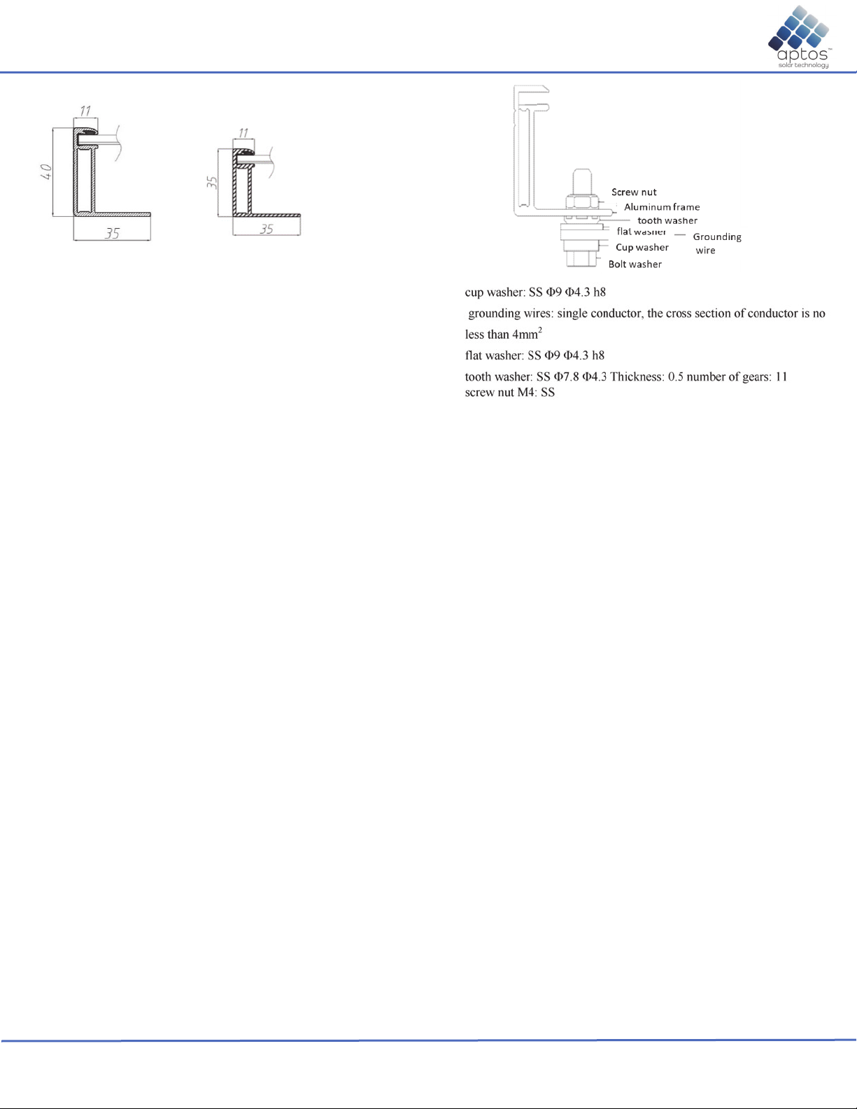
The module is considered to be in compliance with this
standard only when the module is either mounted in the
manner specified by the mounting instructions, or when
the mounting means has been evaluated with this PV
module to UL 2703. A module with exposed conductive
parts is considered to be in compliance with this
standard only when it is either electrically grounded in
accordance with the manufacturer’s instructions and the
requirements of the National Electrical Code,
ANSI/NFPA 70 (2014-2017), or when the bonding
means has been evaluated with this PV module to UL
2703.
Fire Rating
If mounted over a roof, the solar panel shall be mounted
over a fire-resistant roof covering rated for the
application. Refer to local authority for guidelines and
regulations for building fire protection and required
slope. The module fire performance rating is Type I.
Installing the Panel
Aptos Solar Technology panels may be installed in various
applications. The particular mounting is to be defined by the
system designer. Installer must handle and mount the
modules to prevent any impact on front surface, back surface,
and frames as this could result in damage.
Support structures used to support AST DNA panels
should be wind rated and approved for use by the
appropriate codes prior to installation. In addition, they
must be designed from materials that retain structural
integrity over the 25 years lifespan of the panels they
support.
AST DNA panels may be installed in portraits or
landscape orientation.
A minimum of tilt angle of 5 degrees is required to
ensure drainage and enable rainwater.
The junction box edge should be at the top when
mounted in portrait orientation.
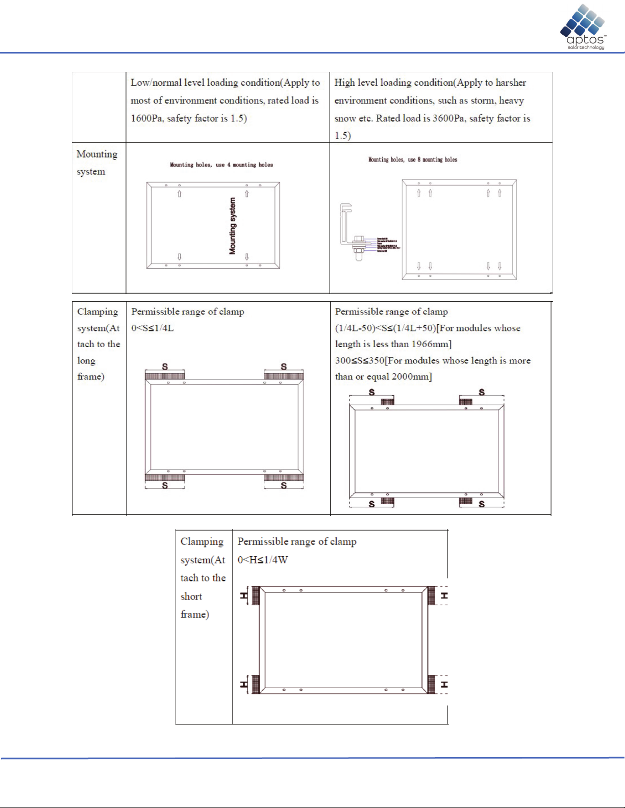
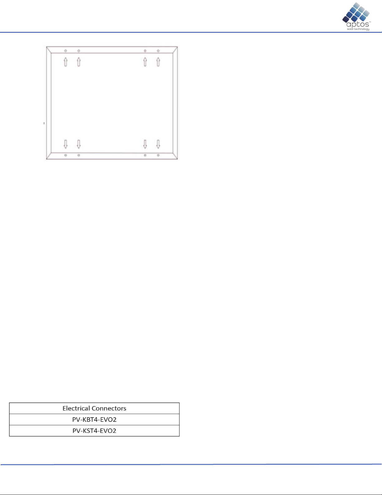
Specific rails and frame clips approved by AST are
listed in Table 1. Alternative rails and frame
clips/fasteners need to be approved by AST to ensure
compliance to UL61730 safety standard.
De-rating factors must be applied if installed above
2000m.

Installation Manual
High Efficiency Half-CellModule
2
www.aptossolar.com | info@aptossolar.com All Rights Reserved. DNA-120/144
Version: AS-IM-001
Frame Cross Section
Module Wiring
AST DNA panels are pre-wired and terminated with
MC4 compatible connectors.
Connections to other panels should use compatible
connectors that comply with Code requirements. AST
recommends that all wiring be double insulated with a
minimum rating of 90 C, and wiring should use flexible
copper conductors where minimum size should be
determined by the applicable codes.
The cables and connectors are UV and weather
resistant from -40 C to +90 C and rated for 1500VDC.
Panels may be wired in series or parallel to obtain
desired voltages and current but must not exceed the
system rating for voltage and current.
AST panels may produce up to 20% more power than
STC rating, depending on system design and albedo.
The additional power gain should be taken into
consideration when determining optimum system sizing,
string length, and selecting system components and
wiring.
Overcurrent protection devices should be employed.
20A current rating for series or parallel. Please comply
with all code and design requirements.
Grounding
NEC, article 250 governs grounding method. Grounding
method must follow local electric codes. Use bolt, M4,
cup washer, grounding wires, flat washer, tooth washer,
screw nut, M4 and install as shown in the diagram
below.
Torque specification is 2 to 3 Nm. Grounding materials
is evaluated under UL1703.
Specifications
The electrical characteristics are within ±10 %of the
indicated values of Isc, Imp, Vmp, and Voc and ± 3 % of
the indicated value Pmax under standard testing
conditions (irradiance of 1000/m2, AM 1.5 spectrum,
and a cell temperature of 25 C)
Under normal conditions, solar panels are likely to
experience conditions that produce more current and/or
voltage than stated at standard test conditions.
Accordingly, thevalues of Isc and Voc, inclusive of
bifacial gain, should bemultiplied by a factor of 1.25, or
more, when determining component voltage ratings,
and size of controls connected to the PV output. (Refer
to code and design requirements).
AST DNA panels have a maximum system voltage of
1500 VDC. Some grid-tied systems operate or near this
voltage rating. The Voc increases as the ambient
temperature decreases.
Maximum system voltage is computed as the sum of
the open-circuit voltage of the series-connected panels
for the lowest expected ambient temperature.
Temperature coefficients can be used to provide the
most accurate prediction of the panel voltage under
temperature extremes.

Installation Manual
High Efficiency Half-CellModule
3
www.aptossolar.com | info@aptossolar.com All Rights Reserved. DNA-120/144
Version: AS-IM-001
Maintenance
ASTDNA panels are designed to require little to no
maintenance. Depending on local conditions, panels
may need periodic cleaning to remove dirt build-up and
soiling. Panels should be washed with water to remove
dirt and soiling. Frequency of cleaning will depend on
local weather conditions and panel tilt. Once a year,
have qualified service professional check the general
condition of wiring and check to be sure that mounting
hardware is at the correct torque. Loose connections
may result in damaged panels.
Panels generate electricity when there is sunlight, and
cleaning/maintenance personnel must take proper
precautions.
Mechanical Drawings
Installers must use pre-drilled mounting holes on the
frame.
Frame clip must have minimum height dimension as
shown.
End Frame Clip
Mid Frame Clip
Mounting Methods
Mounting holes are 14mm by 9mm. M8 bolt and
fasteners.
Torque value is 12.5 Nm – 18 Nm.
Rails can run perpendicular or parallel to panel length.
(See figure 1)
Fasteners
General Information
Slope should be less than 5 in/ft (127 mm/305mm)
required to maintain a fire class rating. Any roof
penetration required to mount the module must be
properly sealed to prevent leaks. The modules are rated
fire class C and are suitable for mounting over class A
roof.
Pole Mount
When installing a module on a pole, choose a pole and
module mounting structure that will withstand
anticipated winds for the area.
Modules Installed with Mounting Holes
Modules should be bolted with M8 and M6 to the
support structures through mounting holes located in
the frame in the back flanges. See table in the following
page. Torque should be 12.5-18 Nm for tightening the
M8 bolt, the torque should be 9-15 Nm for tightening the
M6 bolt.
Modules Installed with Clamping
Modules should be bolted to the support
structures rail by metal clamps. It is recommended
to use clamp under the following conditions or
approved by system installation. Clamping distance
is quarter of the module length. See table in the
following page.
Clamp materials: Aluminum, Bolt torque: 12.5 – 18
NM, clamp must not contact the front glass,
bolt: M8 SS, flat washer: diameter 16-8.4 mm H1.6
ss, spring washer: diameter 12.6-8.4 mm H4.7 ss.

Installation Manual
High Efficiency Half-CellModule
4
www.aptossolar.com | info@aptossolar.com All Rights Reserved. DNA-120/144
Version: AS-IM-001

Installation Manual
High Efficiency Half-CellModule
5
www.aptossolar.com | info@aptossolar.com All Rights Reserved. DNA-120/144
Version: AS-IM-001
DNA 108-MF10-395W, 390W, 400W
STCrated Output P
mpp
(W)
Module ELciency
Open Circuit Voltage V
VOC
(V)
Short Circuit Current I
SC
(A)
Rated Voltage V
mmp
(V)
Rated Current I
max
(A)
390W 395W 400W
19.97% 20.20% 20.47%
36.85 36.98 37.04
13.61
30.64
12.73
13.7
30.84
12.81
13.79
31.01
12.9
2
, 25°C, measurement uncertainty <3%
Temperature Coe ients
Temperature CoeLcients Pmmp
Temperature CoeLcients Isc
Temperature CoeLcients VOC
-0.35%/°C
+0.054%/°C
-0.27%/°C
45°C
Maximum Series Fuse
Maximum System Voltage
Maximum Load Capacity (Per UL 1703)
Fire Performance Class
25A
1,500 VDC (UL&IEC)
5400 PA Snow Load / 5400 Pa Wind Load
Class C/Type 1
DNA-108-MF10-390W DNA-108-MF10-395W DNA-108-MF10-400W

1722mm
1134mm 35mm
1300mm
990mm
Installation Manual
High Efficiency Half-CellModule
6
l|if@ l All Ri h R d DNA 120/144

Installation Manual
High Efficiency Half-CellModule
7
www.aptossolar.com | info@aptossolar.com All Rights Reserved. DNA-108
Version: AS-IM-001
Junction Box Information
Overcurrent protection type: none
# of bypass diodes: 3
Diameter of cables: every module has 2 cables
whose diameter is 4mm2for any one of them, and
it can endure 90oC insulation and can be exposed
under sun light.
Ways of connecting
Every module with 2 connectors that are positive
electrode and negative electrode. When modules
are installed in series, the first positive connector
should connect with the negative connector of the
next module.
The modules are equipped with PV wiring
connectors that comply with the Standard for
Connectors for use in photovoltaic systems, UL
61730, the specific allowable mating connector
manufacturer and model number are listed as
below.
Mounting holes are 1/4 and 1/8 of the panel
length.
This manual suits for next models
3
Table of contents
Other aptos Solar Panel manuals
Popular Solar Panel manuals by other brands

Clenergy
Clenergy PV-ezRack SolarBase installation guide

STC
STC Solar SPA Collector Kit installation guide

Baxi
Baxi SOLAR EASY PV installation manual

STIEBEL ELTRON
STIEBEL ELTRON SOL 27 PREMIUM S Operation & installation manual

boviet SOLAR
boviet SOLAR Vega BVM7612M H-HC-BFDG Series Installation and maintenance manual

Qazqa
Qazqa Elif WL 1 Black Solar instruction manual