Apxteck AT?MG250 User manual

AT‐MG250UserManual–V1.02
AT‐MG250Micro‐inverterInstallationManual
ApxteckRenewableTechnologyCo.,Ltd.

AT‐MG250UserManual–V1.02
ThanksforchoosingApxteckMicro‐Inverter.Foryourownsafetyandtoensuretheoperationof
theequipment,pleasereadthismanualcarefullybeforeinstallationandoperation.
Allrightsreserved:Apxteckreservestherighttochangetheproductandthecontentofthis
manualwithoutWARNING.Usersarerecommendedtovisitthecompanywebsite
www.apxteck.comformoreinformationaboutnewproductsandlatestversionsofuser
manuals.
Forthefurtherinformationortechnicalsupport,pleasecontactus.
ApxteckRenewableTechnologyCo.,Ltd.
Add.:Nr.245XinJunhuanRd.,MinhangDist.,Shanghai201114,China.
Tel.:+862151619916
Fax.:+862151619917
www.apxteck.com

AT‐MG250UserManual–V1.02
TableofContents
GENERALINFORMATION .................................................................................................................7
GENERALINTRODUCTIONFORTHEAT‐MG250MICRO‐INVERTERSYSTEM ...........................................................7
SPECIFICATIONSSHEET&PARAMETERS ..........................................................................................................8
SYMBOLSUSED.........................................................................................................................................9
INSTALLATIONPROCEDURES............................................................................................................9
THINGSTOBECHECKEDBEFOREINSTALLINGAT‐MG250..................................................................................9
STEP1:AFFIXTHESERIALNUMBERTOSYSTEMMAP .....................................................................................10
STEP2:ATTACHTHEAT‐MG250TOTHERACK .............................................................................................10
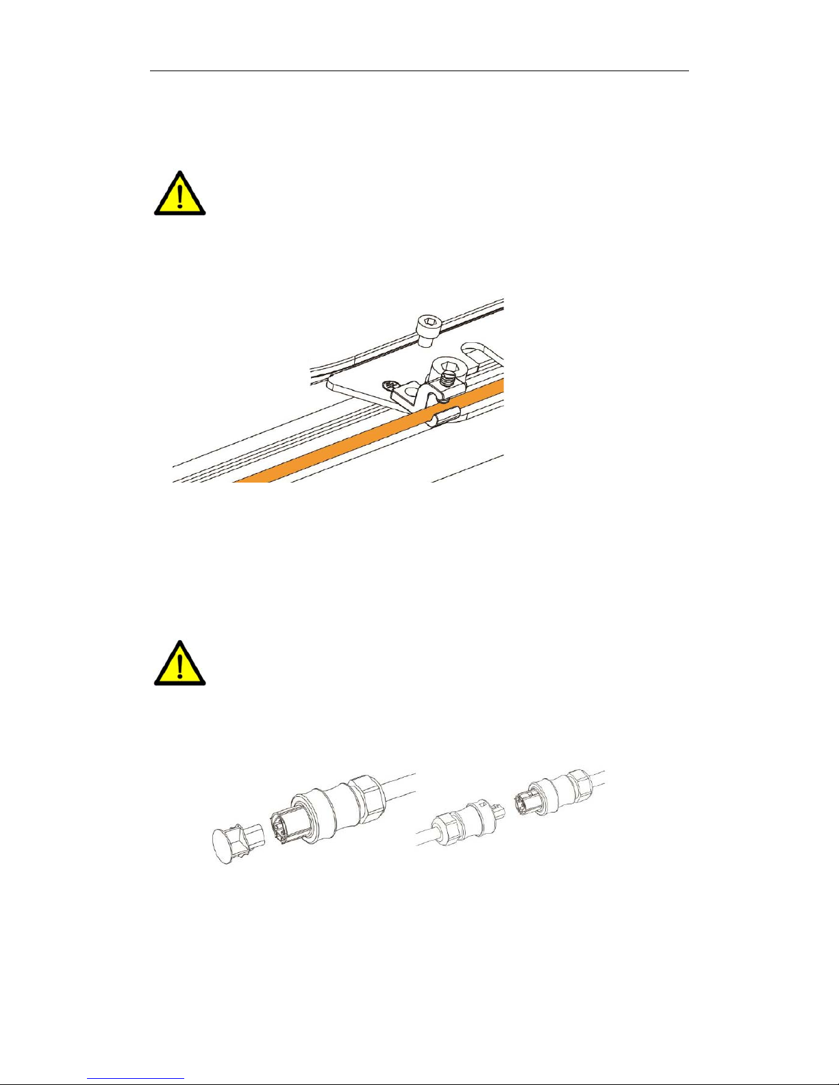
STEP3:GROUNDTHESYSTEM ...................................................................................................................11
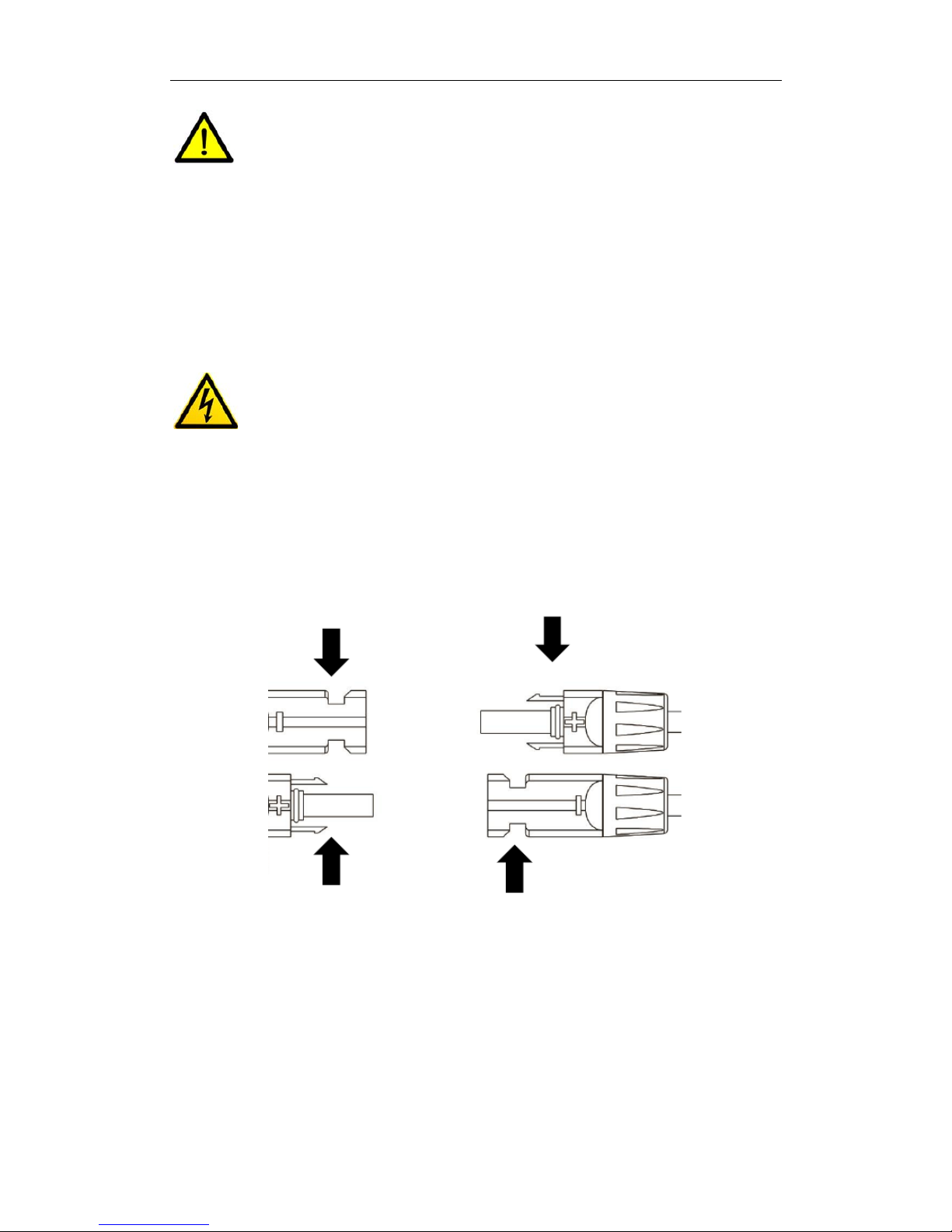
STEP4:CONNECTINGTHEAT‐MG250WITHPVMODULE .............................................................................11
STEP5:CONNECTINGTHEAT‐MG250TOTHEACBREAKER............................................................................12
GENERALCONNECTINGCONFIGURATION .....................................................................................................12
STEP6:COMMISSIONING .........................................................................................................................12
AT‐MG250REPLACEMENT..............................................................................................................13
STEP1:DISCONNECTDCCABLES................................................................................................................13
STEP2:DISCONNECTACCABLES................................................................................................................13
STEP3:LOOSELAY‐INLUGONAT‐MG250 ..................................................................................................14
STEP4:LOOSETHEMOUNTINGSCREWS.......................................................................................................14
ACCESSORIES.................................................................................................................................14
MAINTENANCE&LEDINDICATIONS...............................................................................................15
MAINTENANCE .......................................................................................................................................15
LEDINDICATIONS....................................................................................................................................15
APPENDIX .....................................................................................................................................16
FACTORYLIMITEDWARRANTY....................................................................................................................16
WIRINGDIAGRAM...................................................................................................................................18
SYSTEMMODULEMAP ............................................................................................................................19

AT‐MG250UserManual–V1.02
GeneralInformation
GeneralIntroductionfortheAT‐MG250Micro‐invertersystem
Witharevolutionarytechnology,AT‐MG250Micro‐invertermaximizestheenergyconversion
fromphotovoltaicsolarmodules,enhancessystemreliability,andgreatlysimplifiesthe
installationandreducesthemaintenancetimeandcost.
EachMicro‐inverterworksindependentlywithonePVmodule,eachPVmodulehasindividual
MaximumPeakPowerTracking(MPPT)andensuresthatthemaximumpowerisexportedtothe
utilitygridregardlessoftheperformanceoftheotherPVmodulesinthearray.WhenPV
modulesinthearrayareaffectedbyshading,soiling,orientation,ormismatch,the
Micro‐inverterensurestopperformancefromallPVmodulesinthearray.
TheAT‐MG250Micro‐inverterisagridconnecteddevice.Employsadvanceddigitalcontrol
technologytoinvertDCtoACwhichhastheidenticalfrequencyandphaseanduploadittothe
utilitygrid.ThefeaturesofAT‐MG250Micro‐inverteraresimplifiedinstallation,reliability,
stability,maximumenergyharvestandintelligentmonitoring.Thecompletedself‐protection
functionsgreatlyimprovethestabilityandreliabilityofthesolarsystem.
TheAT‐MG250Micro‐invertersysteminclude,
●AT‐MG250Micro‐inverter,
●AT‐PR4KSolarPowerRouter,
●PowerHubweb‐basedmonitoringandanalysisinterface.

AT‐MG250UserManual–V1.02
Specificationssheet&Parameters

AT‐MG250UserManual–V1.02
SymbolsUsed
Toreducetheriskofelectricalshock,andtoensurethesafeinstallationandoperationofthe
Micro‐Inverter,pleasereadthismanualcarefullyandpayattentiontothesafetysymbolsappear
throughoutthismanual.
DANGER
Thisindicatesahazardoussituation,whichifnotavoided,willresultindeathorseriousinjury.
WARNING
Thisindicatesasituationwherefailuretofollowinstructionsmaybeasafetyhazardorcause
equipmentmalfunction.Useextremecautionandfollowinstructionscarefully.
NOTE
TheNOTEsymbolsinthismanualindicateimportantproductinformation.
InstallationProcedures
ThingstobeCheckedbeforeInstallingAT‐MG250
ToinstallaApxteckMicro‐invertersystem,pleasehaveyourinstallertoreviewfollowingitems
first:
●ReadthespecificationsandwarningsoftheAT‐MG250Micro‐inverter,
●TypeofroofmaterialsuitableforinstallPVsystem,
●BroadbandInternetconnectionisneededforgenerationdataupload,
●AvailableEthernetsocket,
●Sufficientpublicgridpoint.
DANGER
AnyonewhoinstallsorreplacestheAT‐MG250Micro‐invertermustbeauthorizedandlicensed
personnel,whocanensurethesafetypracticeofaqualifiedassembly,installationor
replacement.
WARNING
DonotconnecttheAT‐MG250Micro‐invertertotheutilitygriduntilyouhavecompletedallof
theinstallationproceduresasdescribedinthefollowingsections.

AT‐MG250UserManual–V1.02
WARNING
AT‐MG250Micro‐invertermatchwithmostPVmodules,pleasemakesurethemodule’sspecs
suitablewithMicro‐inverter’srange.
Step1:AffixtheSerialNumbertoSystemMap
TheApxteckSystemMapdisplaylocationofeachMicro‐inverterinyoursystem.Youmaycreate
thevirtualarrayinPowerHubasperthismap.
a. PeelingtheserialnumberlabelsfromtheMicro‐inverters.
b. AttachingthelabelsontheSystemMap.
Version1.00SerialNr.
NOTE
IfadditionalSystemMapneeded,pleasegotowww.apxteck.comtodownload.
Step2:AttachtheAT‐MG250totherack
a. Choosethesuitablemethodofmountingthemicroinverter.
b. Theremustbeatleast10mmclearancebetweentheenclosureoftheMicro‐inverter,the
roofsurfaceandtherearofthePVmodule.

AT‐MG250UserManual–V1.02
Step3:GroundtheSystem
ConsiderusingWEEBtypeclipsforimprovedearthconnection.
WARNING
TheMicro‐invertersmustbegroundedaccordingtolocalstandards.Groundingregulationsmay
varybymarket,makesuretofollowlocalrequirements.
Step4:ConnectingtheAT‐MG250withPVModule
ACcables
a. ConnecttheMicro‐inverterstoeachotherthroughACinterconnectioncables.
b. Listenforaclickasconnectorsengage.
c. CoveranyunusedACconnectorwithasealingendcap.
WARNING
Donotexceed16piecesofAT‐MG250Micro‐invertersconnectedperbranch.
DCcables
a. ConnecteachPVmodulestotheMicro‐inverters.

AT‐MG250UserManual–V1.02
WARNING
Makesuretherightpolarityofeachconnector.
Step5:ConnectingtheAT‐MG250totheACbreaker
GeneralConnectingConfiguration
UsetheACextensioncable(5meters)toconnecttheMicro‐invertertotheACbreakerinsidethe
distributionbox.Thecolorcodeofeachterminalisshownbelow.
Yellow/Green‐PE
Brown‐L
LightBlue‐N
L‐Brown
N‐LightBlue
PE‐
Yellow/Green
WARNING
FollowthelocalelectricalcodesandNationalelectricalcodesforwiring.
Step6:Commissioning
a. Checkallabovesteps(1~5).
b. TurnontheACbreakeroftheMicro‐invertersystem.
WARNING
QualifiedpersonnelonlymayconnecttheApxteckMicro‐invertertothepublicgridafterreceiving
approvalfromtheelectricalutilitycompany.

AT‐MG250UserManual–V1.02
WARNING
AT‐MG250Micro‐inverterisGrid‐connecteddevice.DonotconnectthisunittoanACsourceorany
electricappliances.
AT‐MG250Replacement
IftheApxteckMicro‐inverterinyoursystemcannotworkproperly,pleasefollowstepsbelowto
replacethedefectiveMicro‐inverter.
DANGER
AnyonewhoinstallsorreplacestheAT‐MG250Micro‐invertermustbeauthorizedandlicensed
personnel,whocanensurethesafetypracticeofaqualifiedassembly,installationor
replacement.
Step1:DisconnectDCcables
DisconnecttheDCcablesbetweentheMicro‐inverterandthePVmodule’sjunctionbox.
Step2:DisconnectACcables
PressthehookontheACconnectortodisconnecttheACcables.

AT‐MG250UserManual–V1.02
Step3:Looselay‐inlugonAT‐MG250
Step4:Loosethemountingscrews
Accessories
YouwillfindthecorrespondingaccessoriesandsparepartsforyourMicro‐invertersysteminthe
followingtable.Ifrequired,youcanorderthemfromApxtecklocaldistributor.

AT‐MG250UserManual–V1.02
Maintenance&LEDIndications
Maintenance
Safetychecksshouldbeperformedatleastevery12monthsbyacompetentperson.Items
include,
a. Checktheoperationoftheinverter.SeethattheLEDisflashinginanormalstatus
b. Checkthecasingoftheinverterforanysignsofdamageorcorrosion.
c. Checktheinputandoutputcablesforsignsofcorrosion,rodentdamageoroverheating.
d. Checktheconditionofheconnectorforsignsofcorrosionoroverheating.
e. CheckthePVmodulesforbuildupofdebrisoranyheatspots.
LEDIndications
YoucanchecktheAT‐MG250Micro‐Inverter’sLEDtodetecttheoperationconditions.

AT‐MG250UserManual–V1.02
Appendix
FactoryLimitedWarranty
ApxteckMicro‐invertersandPVPowerRouteraredesignedtobehighlyreliable,haveaverylong
lifefortheiroriginallyintendedpurpose,abletowithstandnormaloperatingconditions
andordinarywearandtearincompliancewithallApxteckuserandinstallationmanualsand
instructions.TheApxtecklimitedproductwarrantycoversdefectsinworkmanshipandmaterials
foraperiodoftwenty‐fiveyears(forMicro‐inverter)andaperiodoffiveyears(forPVPower
Router)subjecttothetermsandconditionsherein.
ThiswarrantyisprovidedtothepurchaseroftheApxteckproduct,andthewarrantyperiod
beginswiththedateofsale.ThewarrantyisvalidforownersofinstalledsystemsusingApxteck
Micro‐inverterandPVPowerRouter.
DuringtheWarrantyPeriod,ApxteckRenewableTechnologyCo.,Ltd.will,atitsoption,repairor
replacedefectiveApxteckproductfreeofcharge,subjecttoApxteckverificationofdefect(s)
coveredbythisLimitedWarranty.Apxteckwill,atitsoption,usenewand/orreconditionedparts
inrepairingorreplacingdefectiveproduct.Apxteckmayatitsdiscretionusepartsorcomponent
ofitschoosingtorepairorreplacethedefectiveproductasoriginalcomponentsmaynolonger
bepracticallyavailableand/ornewcomponentsand/ordesignshavesupersededthedefective
Apxteckproduct.
RepairedorreplacedApxteckproductcontinuetobewarrantedfortheremainingtermofthe
originalwarranty.
ThisLimitedWarrantydoesincludethecostofshippingdefectivemicro‐inverterstoApxteckand
thereturnofrepairedorreplacementmicro‐invertersunderApxteck’instructionsandusinga
freightcarrierofApxteck’choosing.ThisLimitedWarrantydoesnotextendbeyondtheoriginal
costoftheApxteckMicro‐inverter.
ToobtainrepairorreplacementserviceunderthisLimitedWarranty,thecustomermustcomply
withthefollowingpolicyandprocedure:
AReturnMerchandiseAuthorizationNumber(RMA)mustbeobtainedfromApxteckRenewable
TechnologyCo.,Ltd.beforereturninganyproductforrepairorreplacement.ToissuetheRMA,
Apxteckrequires:
•Proof‐of‐purchaseoftheDefectiveProductfromApxteck,
•ModelandSerialnumberoftheDefectiveProduct,
•Detaileddescriptionofthedefectastheformneedtobefilled
•Shippingaddressforreturnoftherepairedorreplacementproduct.
Alldefectiveproductauthorizedforreturnmustbereturnedinpackagingthatissuitably
protectiveoftheproduct.
TheAPXTECKLimitedProductWarrantydoesnotapplyto,andApxteckwillnotberesponsible
for:
1) ThecoststoanalyseanddiagnoseaMicro‐inverter(orPVPowerRouter)failureatthe

AT‐MG250UserManual–V1.02
installationbytheinstallerorsystemownerarenotcovered.
2) Laborcoststoun‐installdefectiveApxteckMicro‐inverters(orPVPowerRouter)or
re‐installingrepairedorreplacedApxteckMicro‐inverters(orPVPowerRouter)arenot
covered.
3) ApxteckisnotresponsibleforreturnedMicro‐inverters(orPVPowerRouter)lost,damaged
ormishandledintransit.
4) Micro‐inverters(orPVPowerRouter)thathavebeenmisused,neglected,tamperedwith,
altered,disassembled,modifiedorotherwisedamaged,eitherinternallyorexternallyare
notcovered.
5) Micro‐inverters(orPVPowerRouter)thathavebeenimproperlyinstalled,operated,handled
orused,includinguseunderconditionsforwhichtheproductwasnotdesigned,operatedin
anymannerthatexceedsitsspecification,useinanunsuitableenvironment,oruseina
mannercontrarytotheApxteckuserandinstallationmanualsorinviolationofapplicable
lawsorregulationsareexcluded.
6) Micro‐inverters(orPVPowerRouter)thathavebeensubjectedtofire,submersioninwater,
generalizedcorrosion,biologicalinfestations,actsofGod,orinputvoltagethatcreates
operatingconditionsbeyondthemaximumorminimumlimitslistedintheApxteck
Micro‐inverter(orPVPowerRouter)specificationsorcertificationrequirementsdocuments,
includinghighinputvoltagefromgeneratorsorlightningstrikesarenotcovered.
7) Micro‐inverters(orPVPowerRouter)thathavebeensubjectedtoincidentalorconsequential
damagecausedbydefectsofothercomponentsofthesolarsystemarenotcovered.
8) Micro‐inverters(orPVPowerRouter)wheretheoriginalidentificationmarkings(including
trademarkorserialnumber)havebeendefaced,altered,orremoved.
ThisLimitedWarrantydoesnotcovercostsrelatedtotheremoval,installationor
troubleshootingofthecustomer'selectricalsystems.
THELIMITEDWARRANTYISTHESOLEANDEXCLUSIVEWARRANTYGIVENBYAPXTECKAND,
WHEREPERMITTEDBYLAW,ISMADEEXPRESSLYINLIEUOFALLOTHERWARRANTIES,
EXPRESSORIMPLIED,STATUTORYOROTHERWISE,INCLUDING,WITHOUTLIMITATION,
WARRANTIESOFTITLE,QUALITY,MERCHANTABILITY,FITNESSFORAPARTICULARPURPOSE
ORNON‐INFRINGEMENTORWARRANTIESASTOTHEACCURACY,SUFFICIENCYOR
SUITABILITYOFANYTECHNICALOROTHERINFORMATIONPROVIDEDINMANUALSOROTHER
DOCUMENTATION.INNOEVENTWILLAPXTECKBELIABLEFORANYSPECIAL,DIRECT,
INDIRECT,INCIDENTALORCONSEQUENTIALDAMAGES,LOSSES,COSTSOREXPENSES
HOWEVERARISING,WHETHERINCONTRACTORTORT,INCLUDINGWITHOUTLIMITATIONANY
ECONOMICLOSSESOFANYKIND,ANYLOSSORDAMAGETOPROPERTY,ORANYPERSONAL
INJURY.
TotheextentanyimpliedwarrantiesarerequiredunderapplicablelawtoapplytotheAPXTECK
product,suchimpliedwarrantiesshallbelimitedindurationtothewarrantyperiod,tothe
extentpermittedbyapplicablelaw.Someregionsdonotallowlimitationsorexclusionson
impliedwarrantiesoronthedurationofanimpliedwarrantyoronthelimitationorexclusionof
incidentalorconsequentialdamages,sotheabovelimitation(s)orexclusion(s)maynotapply.
ThisLimitedWarrantygivestheownerspecificlegalrights,andtheownermayhaveotherrights
thatmayvaryfromregiontoregion.

AT‐MG250UserManual–V1.02
WiringDiagram

AT‐MG250UserManual–V1.02
SystemModuleMap
Table of contents
Popular Inverter manuals by other brands

YASKAWA
YASKAWA Varispeed G7 instruction manual

SOLIS
SOLIS S5 Series user manual

Solar Stik
Solar Stik 11-1000020 Operator and maintenance manual

Power One
Power One AURORA PVI-STRINGCOMB Installation and instruction manual

Generac Power Systems
Generac Power Systems Guardian 5340 Specification sheet

Advanced Energy
Advanced Energy Paramount MF 2 kW user manual