6/7
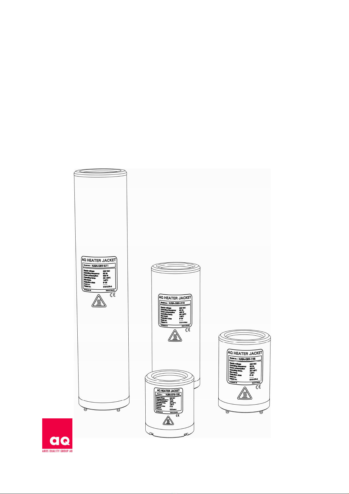
9. Dimensions and weight
Outside dimensions apply unless otherwise stated. The height is measured from the top section of the top ring
to the lower section of the dome nut.
The column filter is an example of a filter housing that matches with each HJ.
Item no. Filter Width Height Top ring Weight Power Supply
mm mm Id kg VAC
HJSA 089 - 572 Advanta 20" 123 572 89 5.0 800 230
HJSB 089 - 572 Advanta 20" 123 572 89 5.0 800 115
HJSA 089 - 318 Advanta 10" 123 318 89 3.0 400 230
HJSB 089 - 318 Advanta 10" 123 318 89 3.0 400 115
HJSA 089 - 185 Advanta 5” 123 185 89 1.8 200 230
HJSB 089 - 185 Advanta 5” 123 185 89 1.8 200 115
HJSA 073 - 130 Junior 440 107 130 73 1.4 100 230
HJSB 073 - 130 Junior 440 107 130 73 1.4 100 115
HJSA 104 - 302 Millipore* 10” 138 302 104 1,6 400 230
HJSB 104 - 302 Millipore* 10” 138 302 104 1,6 400 115
HJSA 104 - 155 Millipore* 5” 138 155 104 1,4 200 230
HJSB 104 - 155 Millipore* 5” 138 155 104 1,4 200 115
HJSA 101 – 302 Sartorius Std. 10” 136 302 102 1,6 400 230
HJSA 101 – 162 Sartorius Std. 5” 136 162 102 1,4 200 230
HJSA 076 – 136 Sartorius mini 5” 110 136 76 1,0 150 230
*
Series 3000
10. Accessories/ Spare parts
Heater acket Control Unit
Item Model Size (WxLxH) Item no.
Heater Jacket Control Unit 230/115 VAC 125x175x110 mm HJCU
Heater Jacket Control Unit Communication
3
230/115 VAC 125x175x110 mm HJCU-COM
Heater Jacket Control Unit Current Communic.
4
230/115 VAC 125x175x110 mm HJCU-COM-S
Supply and alarm connector without cable is included.
Extension cables and alarm cables
Item Length Approval Type Item no.
Supply cable Control Unit Sweden 2.0 metres CEE 7/VII Y003-B/B CCUS
Supply cable Control Unit USA/Canada 2.4 metres UL817, CSA- TA-3/2,4mG/SVT CCUU
CC22.2 n 21
Extension cable kit Heater Jacket
5
2.5 metres CE, UL, CSA Silflex, 3G1,0 HJEC-2M
Extension cable kit Heater Jacket
5
5.0 metres CE, UL, CSA Silflex, 3G1,0 HJEC-5M
Extension cable kit Heater Jacket
5
10.0 metres CE, UL, CSA Silflex, 3G1,0 HJEC-10M
Alarm Cable Heater Jacket 2.5 metres CE, UL, CSA Silflex, 3G1,0 HJAC-2M
Alarm Cable Heater Jacket 5.0 metres CE, UL, CSA Silflex, 3G1,0 HJAC-5M
Alarm Cable Heater Jacket 10.0 metres CE, UL, CSA Silflex, 3G1,0 HJAC-10M
3. Heater Jacket Control Unit Communication – Communicates with RS-485
4. Heater Jacket Control Unit Current Communic. - Communicates with 4-20mA DC
5. Cable kit includes two cables (Temp & Heater cables).