Aqua Computer aquaero 5 Operating manual

AQUAERO 5 / AQUAERO 6
User and installation manual
User and installation manualUser and installation manual
User and installation manual
aquaero 5
aquaero 6
Current as of June 2019
All information contained in t is manual is subject to c ange wit out prior notice.
All rig ts reserved.
© 2014-2019 Aqua Computer GmbH & Co. KG - 1 -
Gellie äuser Str. 1, 37130 Gleic en
c
o
m
p
u
t
e
r
a
q
u
a
ENGLISH: PAGE 1
DEUTSCH: SEITE 53

AQUAERO 5 / AQUAERO 6
Table of contents
Table of contentsTable of contents
Table of contents
1. Scope of delivery..........................................................................6
2. Preface.........................................................................................6
3. Safety precautions.........................................................................6
4. Electrical connectors.....................................................................7
4.1. Connector overview......................................................................7
4.2. Connector “Power”.......................................................................7
4.3. Connector “Fan 1/2/3/4”.............................................................8
4.4. Connector “PWM 1/2”..................................................................8
4.5. Connector “IR LED”......................................................................9
4.6. Connector “aquabus ig ”............................................................9
4.7. Connector “RPM/Tac o”...............................................................9
4.8. Connector “Sensors”...................................................................10
4.9. Connector “USB”........................................................................10
4.10. Connectors “Flow 1” and “Flow 2”.............................................10
4.11. Connector “RGB LED”...............................................................11
4.12. Connector “Relay”....................................................................11
4.13. Connector “Standby” (aquaero 5 only)........................................11
4.14. Compatible optional accessories for t e aquaero 5/6...................12
5. Operation of t e aquaero 5/6 device...........................................12
5.1. Operation via USB connection.....................................................12
5.2. Operation wit out USB connection...............................................12
5.3. Operation via keys and display (aquaero 5/6 PRO and XT only)......12
5.4. Operation via aquaremote (aquaero 5/6 PRO and XT only)............13
5.5. Configuration menu (aquaero 5/6 PRO and XT only)......................13
6. Infrared remote control aquaremote.............................................14
6.1. Modes of operation “aquaero”, “PC keyboard”, “PC media keys”....14
6.2. Special functions in “aquaero” mode............................................14
6.3. Special functions in “PC keyboard” mode......................................15
6.4. Special functions in “PC media keys” mode...................................15
7. Operation concept: Sensor, controller, output...............................15
7.1. Sensors......................................................................................15
7.2. Controllers.................................................................................16
7.3. Outputs.....................................................................................16
8. aquasuite software......................................................................16
8.1. Installation of t e aquasuite software.............................................17
8.2. Basic operation..........................................................................17
8.3. Symbols in t e eadlines..............................................................17
9. Overview pages (aquasuite).........................................................18
9.1. Desktop mode............................................................................18
9.2. Creating new overview pages and activating edit mode..................18
- 2 - Aqua Computer GmbH & Co. KG © 2014-2019
Gellie äuser Str. 1, 37130 Gleic en
c
o
m
p
u
t
e
r
a
q
u
a

AQUAERO 5 / AQUAERO 6
9.3. Adding new elements..................................................................18
9.4. Editing existing elements..............................................................19
9.5. Values and names......................................................................19
9.6. Detailed data elements................................................................19
9.7. Log data c art............................................................................19
9.8. User defined: Images, text, drawing elements.................................20
9.9. Export and import of overview pages.............................................20
10. Data quick view and data log (aquasuite)...................................20
10.1. Log settings..............................................................................21
10.2. Analyze data............................................................................21
10.3. Manual data export...................................................................22
10.4. Automatic data export...............................................................22
11. Sensor configuration (aquasuite/device menu)............................23
11.1. Temperature sensors.................................................................23
11.2. Virtual temperature sensors........................................................23
11.3. Software temperature sensors.....................................................24
11.4. Flow sensors.............................................................................25
11.5. Power measurement..................................................................25
11.6. Fill level sensors........................................................................25
11.7. Pressure sensors........................................................................26
12. Controller configuration (aquasuite/device menu).......................26
12.1. Curve controllers......................................................................26
12.2. Set point controllers..................................................................27
12.3. Two point controllers.................................................................27
12.4. Preset values............................................................................27
12.5. RGB LED controller...................................................................27
13. Fan configuration (aquasuite/device menu)................................28
13.1. Minimum and maximum power..................................................28
13.2. Power, speed or PWM controlled mode.......................................28
13.3. Start boost and output settings....................................................28
13.4. Programmable fuses..................................................................29
14. Output configuration (aquasuite/device menu)...........................29
14.1. LED outputs..............................................................................29
14.2. Power outputs...........................................................................30
14.3. Relay.......................................................................................30
15. Pump configuration (aquasuite/device menu)..............................30
15.1. aquastream ULTIMATE and aquastream XT..................................30
15.2. D5 pumps connected via aquabus..............................................31
16. User interface configuration (aquasuite/device menu, aquaero 5/6
XT/PRO only)...........................................................................31
16.1. Language setting......................................................................32
16.2. Display settings.........................................................................32
© 2014-2019 Aqua Computer GmbH & Co. KG - 3 -
Gellie äuser Str. 1, 37130 Gleic en
c
o
m
p
u
t
e
r
a
q
u
a

AQUAERO 5 / AQUAERO 6
16.3. Key settings..............................................................................32
16.4. Programmable function keys (device menu of aquaero 5/6 XT only)
.................................................................................................32
17. Information page configuration (aquasuite/device menu, aquaero
5/6 XT/PRO only)....................................................................33
17.1. Screens ot function (aquasuite only)...........................................33
17.2. Special pages and logo (aquasuite only).....................................33
17.3. Information pages.....................................................................33
17.4. USB LCD page.........................................................................33
18. Alarm actions (aquasuite/device menu)......................................34
18.1. Alarm suppression after power on...............................................34
18.2. Alarm levels.............................................................................34
19. Alarm configuration (aquasuite/device menu).............................35
19.1. Configure alarm monitoring.......................................................35
19.2. Example configuration for emergency s utdown wit aquaero power
connect:....................................................................................35
19.3. Example configuration for emergency s utdown wit power switc
connector:.................................................................................36
20. Timer configuration (aquasuite/device menu)..............................36
20.1. Configure timer events...............................................................36
21. Infrared configuration (device menu aquaero 5/6 XT/PRO)..........37
21.1. Enable/disable infrared functions................................................37
21.2. Keyboard layout aquaremote.....................................................37
21.3. Trained infrared commands.......................................................37
21.4. PC wake up and s ut down by infrared remote control..................37
21.5. aquaremote multi device mode..................................................37
22. Data log (aquasuite/device menu).............................................38
22.1. Configure log data sets.............................................................38
22.2. Transfer log data into aquasuite (aquasuite only)..........................38
22.3. Save log data as XML (aquasuite only)........................................38
22.4. Delete log data from aquaero memory........................................38
23. Functional upgrades by aquabus devices....................................39
23.1. Compatible aquabus devices.....................................................39
23.2. Fan outputs of aquabus devices..................................................40
23.3. Pumps connected via aquabus...................................................41
23.4. Temperature sensor data from aquabus devices...........................41
23.5. Flow sensor data from aquabus devices......................................42
23.6. Electrical connection of aquabus devices.....................................43
23.7. Listing of currently connected aquabus devices and configuration...44
23.8. Advanced aquabus options........................................................44
23.9. Additional information for aquastream ULTIMATE.........................44
23.10. Additional information for aquastream XT..................................44
- 4 - Aqua Computer GmbH & Co. KG © 2014-2019
Gellie äuser Str. 1, 37130 Gleic en
c
o
m
p
u
t
e
r
a
q
u
a

AQUAERO 5 / AQUAERO 6
24. System settings (aquasuite/device menu).....................................44
24.1. Device information....................................................................45
24.2. Profiles and factory defaults.......................................................45
24.3. System event log.......................................................................45
24.4. Firmware update (aquasuite only)...............................................45
24.5. aquaero 5/6 LT expansion device firmware..................................45
24.6. Standby configuration (device menu only)....................................46
24.7. Overwrite outputs directly..........................................................46
25. aquasuite web..........................................................................46
25.1. Data export..............................................................................47
25.2. Data access.............................................................................47
25.3. Data import..............................................................................47
26. Basic settings (aquasuite)...........................................................48
26.1. Language................................................................................48
26.2. Units.......................................................................................48
26.3. Application start-up...................................................................48
26.4. Service administration...............................................................48
26.5. License manager.......................................................................48
27. Trouble s ooting.......................................................................49
27.1. Device firmware deletion and recovery........................................49
27.2. No USB connection to t e device................................................49
27.3. Outputs do not perform as expected...........................................50
27.4. Controllers/Alarms/Log data is not updated.................................50
27.5. Malfunction of device keys (XT/PRO only)....................................50
27.6. Device does not respond to aquaremote.....................................50
27.7. Expansion board connected to aquabus is not discovered.............51
27.8. Recurring aquabus communication errors detected.......................51
28. Tec nical details and care instructions........................................52
28.1. Tec nical details.......................................................................52
28.2. Care instructions.......................................................................52
28.3. Waste disposal.........................................................................52
28.4. Contact Aqua Computer............................................................52
© 2014-2019 Aqua Computer GmbH & Co. KG - 5 -
Gellie äuser Str. 1, 37130 Gleic en
c
o
m
p
u
t
e
r
a
q
u
a

AQUAERO 5 / AQUAERO 6
1.
1.1.
1. Scope of delivery
Scope of deliveryScope of delivery
Scope of delivery
●One aquaero 5/6 controller
●Four temperature sensors 70 cm (replacement part no. 53026)
●One internal USB cable (replacement part no. 53085)
●One aquabus / speed signal cable (replacement part no. 93111)
●Mounting material
●Quick start manual
aquaero 5 XT and aquaero 6 XT only:
●One aquaremote infrared remote control (replacement part no. 53088)
2.
2.2.
2. Preface
PrefacePreface
Preface
Dear valued customer
Dear valued customerDear valued customer
Dear valued customer,
we congratulate you on t e purc ase of an aquaero made by Aqua Computer
GmbH & Co. KG. We are one of t e most renowned manufacturers of PC water
cooling systems in Germany. Our production meets ig est quality standards.
S ould you ave questions or suggestions regarding our products, you are invited
to visit t e forums on our website www.aqua-computer.de or contact our customer
support.
Considering t e fast tec nical development, we reserve t e rig t to be able to per-
form alterations to t e products at any time. It t erefore is possible t at your prod-
uct does not correspond precisely to t e descriptions or especially t e illustrations
in t is manual.
We ope you will enjoy your new aquaero.
Your Aqua Computer team
3.
3.3.
3. Safety precautions
Safety precautionsSafety precautions
Safety precautions
T e following safety precautions ave to be observed at all times:
●Read t is manual t oroug ly and entirely!
●Save your data onto suitable media before working on your ardware!
●T e aquaero may only be used completely assembled in a computer case!
●Never touc , connect or separate cables or electronic components w ile in
use! T e electronic components and t e eat sink (if installed) may get very
ot during operation! Wait for at least 30 minutes after powering down t e
device before touc ing any components!
●Do not turn on your computer unless you are absolutely certain t at all ca-
bles are securely and correctly connected to t e aquaero!
●T e relay output may be powered at a maximum of 12 V! T e current must
not exceed 1 Ampere!
- 6 - Aqua Computer GmbH & Co. KG © 2014-2019
Gellie äuser Str. 1, 37130 Gleic en
c
o
m
p
u
t
e
r
a
q
u
a

AQUAERO 5 / AQUAERO 6
●T is product is not designed for use in life support appliances, devices, or
systems w ere malfunction of t is product can reasonably be expected to re-
sult in personal injury. Aqua Computer GmbH & Co. KG customers using or
selling t is product for use in suc application do so at t eir own risk and
agree to fully indemnify Aqua Computer GmbH & Co. KG for any damages
resulting from suc application!
4.
4.4.
4. Electrical connectors
Electrical connectorsElectrical connectors
Electrical connectors
ATTENTION: Completely turn off your power supply unit or disconnect t e mains
power cord from t e wall outlet before connecting or disconnecting any cables
to/from t e device! T e PCB and components may get very ot during operation!
Wait for at least 30 minutes after powering down t e device before touc ing t e
PCB, eat sink or any components of t e device!
4.1.
4.1.4.1.
4.1. Connector overview
Connector overviewConnector overview
Connector overview
T e following sc ematic s ows t e connectors of t e aquaero 5/6 units:
4.2.
4.2.4.2.
4.2. Connector “Power”
Connector “Power”Connector “Power”
Connector “Power”
Please connect a HDD power plug of your PSU to t is connector. Do not use ex-
cessive force but double c eck t e polarity of t e plug if you are aving trouble to
connect.
Pin assignment: Pin 1 +12 V
Pin 2 GND
© 2014-2019 Aqua Computer GmbH & Co. KG - 7 -
Gellie äuser Str. 1, 37130 Gleic en
c
o
m
p
u
t
e
r
a
q
u
a

AQUAERO 5 / AQUAERO 6
Pin 3 GND
Pin 4 +5 V
4.3.
4.3.4.3.
4.3. Connector “Fan 1/2/3/4”
Connector “Fan 1/2/3/4”Connector “Fan 1/2/3/4”
Connector “Fan 1/2/3/4”
Voltage regulated fan outputs wit speed signal processing.
aquaero 5:
Maximum output power is 19.8 W (1.65 A at 12 V) for eac c annel. Maximum
power is dynamically limited t roug temperature monitoring and will decrease
considerably at lower output voltages. In case an output amplifier temperature
rises to ca. 95 °C, t e output is set to 100 % power. After cooling down to ca.
70 °C, normal operation will resume. If t e temperature rises to ca. 100 °C, t e
output will be permanently disabled. To reactivate t e output, t e aquaero (or
t e complete PC) as to be disconnected from power for a s ort period of time.
Despite t is overload protection, t e fan outputs are not s ort-circuit proof!
Special feature “Fan 4”:
Special feature “Fan 4”:Special feature “Fan 4”:
Special feature “Fan 4”: T is connector can be used for conventional fans or
→ →PWM controlled fans. For PWM fans, select “Outputs” “Fans” “Fan 4” from
t e menu and set “Control mode” to “PWM controlled”.
aquaero 6:
Maximum current is 2.5 A per output independent of output voltage, resulting in
a maximum power of 30 W at 12 V. Outputs will be switc ed off if amplifier
temperatures reac a critical level and will automatically be reactivated w en
cooled down. If an output current of 3 A is exceeded, t e output will be perma-
nently disabled. To reactivate t e output, t e aquaero (or t e complete PC) as
to be disconnected from power for a s ort period of time. T e fan outputs are
s ort-circuit proof.
All fan connectors can be used for conventional fans or PWM controlled fans.
→ →For PWM fans, select “Outputs” “Fans” “Fan 1-4” from t e menu and set
“Control mode” to “PWM controlled”.
Pin assignment: Pin 1: GND
Pin 2: 0-12 V
Pin 3: Speed signal
Pin 4: PWM signal (aquaero 5: Fan 4 only)
4.4.
4.4.4.4.
4.4. Connector “PWM 1/2”
Connector “PWM 1/2”Connector “PWM 1/2”
Connector “PWM 1/2”
Pulse widt modulated 12 V outputs, maximum current load 1 A, carrier frequency
15 kHz. Suitable for example for 12 V LEDs, not compatible wit PWM fans or
pumps.
Pin assignment: Pin 1: VCC
Pin 2: GND
Compatible products:
- 8 - Aqua Computer GmbH & Co. KG © 2014-2019
Gellie äuser Str. 1, 37130 Gleic en
c
o
m
p
u
t
e
r
a
q
u
a

AQUAERO 5 / AQUAERO 6
●Plug for PWM connector, 2 contacts (53036)
4.5.
4.5.4.5.
4.5. Connector “IR LED”
Connector “IR LED”Connector “IR LED”
Connector “IR LED”
Not operational, reserved for future use.
4.6.
4.6.4.6.
4.6. Connector “aquabus ig ”
Connector “aquabus ig ”Connector “aquabus ig ”
Connector “aquabus ig ”
Connector for communication wit ot er devices from Aqua Computer.
Compatible products:
●Real Time Clock module (53127)
●Aqua Computer D5 NEXT (41118)
●aquastream ULTIMATE (41108)
●aquastream XT ( 41059/41060/41061)
●QUADRO (53256)
●Calitemp digital temperature sensor (53257)
●aquabus X4 (53258)
●Flow sensor “ ig flow USB” (53129)
●Flow sensor mps flow 100/200/400 (53130/53131/53132)
●poweradjust 3 USB (53166/53167)
●poweradjust 2 USB (discontinued, firmware version 1003 or ig er required)
●farbwerk (53170/53207)
●aqualis XT series
●aquainlet XT series
●pump adapter for aqualis wit integrated fill level sensor
●mps pressure ∆40/100/500/1000 (53133/53134/53135/53160)
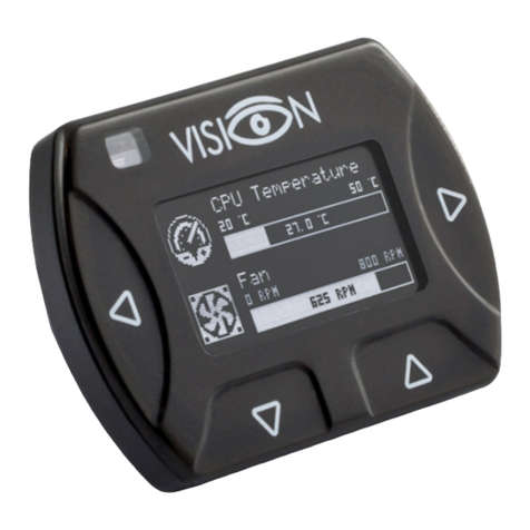
●VISION series
●aquabus / speed signal cable 3 pin (article no. 93111/53161)
●aquabus Y adapter 3 pin (article no. 53063)
●aquabus cable 4 pin (article no. 53122/53162)
●aquabus Y adapter 4 pin (article no. 53124)
●aquabus cable 4 pins for VISION, QUADRO, D5 NEXT (article no. 53214)
Please note:
Please note:Please note:
Please note: T e aquabus connector is also compatible wit 3 pin aquabus de-
vices. T e additional “pin 4” supplies power to compatible 4 pin aquabus devices.
For example, a poweradjust 3 unit (3 pin) and a mps flow 200 unit (4 pin) can si-
multaneously be connected using a 4 pin Y adapter cable (art. 53124).
Pin assignment: Pin 1: GND
Pin 2: SDA
Pin 3: SCL
Pin 4: +5 V
4.7.
4.7.4.7.
4.7. Connector “RPM/Tac o”
Connector “RPM/Tac o”Connector “RPM/Tac o”
Connector “RPM/Tac o”
Depending on configuration, t e aquaero 5/6 can generate a speed signal w ic
is available for processing t roug t is connector. T is speed signal can for exam-
© 2014-2019 Aqua Computer GmbH & Co. KG - 9 -
Gellie äuser Str. 1, 37130 Gleic en
c
o
m
p
u
t
e
r
a
q
u
a

AQUAERO 5 / AQUAERO 6
ple be configured to cease function upon alarm events and t ereby relay t e
alarm status to a fan connector of your mot erboard. Functionality of t e speed
signal can be configured using t e menu entries “Alarm” and “Timer”. For details
on ow to configure your mot erboard to process t e speed signal, please refer to
t e manual of your mot erboard.
Compatible products:
●aquabus / speed signal cable 3 pin (article no. 93111/53161)
4.8.
4.8.4.8.
4.8. Connector “Sensors”
Connector “Sensors”Connector “Sensors”
Connector “Sensors”
Connector for up to 8 temperature sensors.
Pin assignment: Pin 1/2: Sensor 1
Pin 3/4: Sensor 2
Pin 5/6: Sensor 3
Pin 7/8: Sensor 4
Pin 9/10: Sensor 5
Pin 11/12: Sensor 6
Pin 13/14: Sensor 7
Pin 15/16: Sensor 8
Compatible sensors:
●Temperature sensor inline G1/4 (53066)
●Temperature sensor inner/outer t read G1/4 (53067)
●Temperature sensor G1/4 (53147)
●Temperature sensor plug&cool (53025)
●Temperature sensor 70 cm (53026)
4.9.
4.9.4.9.
4.9. Connector “USB”
Connector “USB”Connector “USB”
Connector “USB”
T is connector is used for USB communication to t e PC and for standby power
supply. Take special care to make sure t e pin alignment matc es your mot er-
board!
Pin assignment: Pin 1 +5 V (red)
Pin 2 D- (w ite)
Pin 3 D+ (green)
Pin 4 GND (black)
Pin 5 not connected
4.10.
4.10.4.10.
4.10. Connectors “Flow 1” and “Flow 2”
Connectors “Flow 1” and “Flow 2”Connectors “Flow 1” and “Flow 2”
Connectors “Flow 1” and “Flow 2”
Connectors for flow sensors. Use sensors and cables specified by Aqua Computer
only!
Please note:
Please note:Please note:
Please note: T e “Flow 2” connector may also be labeled as “aquabus low” on
t e device. T e function of t is eader is determined solely by t e current firmware
version of t e aquaero. Starting wit firmware version “2010”, t is eader can be
connected to a flow sensor irrespective of connector labeling.
- 10 - Aqua Computer GmbH & Co. KG © 2014-2019
Gellie äuser Str. 1, 37130 Gleic en
c
o
m
p
u
t
e
r
a
q
u
a

AQUAERO 5 / AQUAERO 6
Pin assignment: Pin 1: GND
Pin 2: 5 V
Pin 3: Speed signal
Compatible flow sensors:
●Flow sensor wit 5.6 mm nozzle (53061)
●Flow sensor “ ig flow” (53068)
●Connection cable for flow sensor (53027, 53100)
4.11.
4.11.4.11.
4.11. Connector “RGB LED”
Connector “RGB LED”Connector “RGB LED”
Connector “RGB LED”
Connector for up to t ree LEDs or one two-color or RGB illumination module (not
included in delivery). Hig brig tness LEDs (2-3.2 V, 20 mA) may be connected
wit out series resistor, a series resistor is built into t e aquaero.
Pin assignment: Pin 1: VCC LED 1 (red, for 2.1 V forward voltage)
Pin 2: VCC LED 2 (green, for 3.2 V forward voltage)
Pin 3: GND
Pin 4: VCC LED 3 (blue, for 3.2 V forward voltage)
Compatible products:
●RGB illumination module (34930)
4.12.
4.12.4.12.
4.12. Connector “Relay”
Connector “Relay”Connector “Relay”
Connector “Relay”
Floating contact (c angeover contact). May be used for emergency s utdown of
t e PC w ic requires additional accessories (art. no. 53047 and 53080, not in-
cluded in delivery) or for free use. Maximum contact rating 1 A, 12 V.
Pin assignment aquaero 5: Pin 1: normally open
Pin 2: normally connected
Pin 3: common connector
Pin assignment aquaero 6: Pin 1: normally connected
Pin 2: normally open
Pin 3: common connector
Compatible products:
●Plug for relay connector, 3 contacts (53080)
●aquaero power connect - 24 pin ATX standby power / ATX break (53047)
4.13.
4.13.4.13.
4.13. Connector
ConnectorConnector
Connector “Standby” (aquaero 5 only)
“Standby” (aquaero 5 only) “Standby” (aquaero 5 only)
“Standby” (aquaero 5 only)
Connector for additional power supply from t e 5 Volts standby power line of t e
power supply unit. If connected to standby power, t e aquaero 5 will remain func-
tional w ile t e computer is in soft off state even if no USB standby power is sup-
plied. For use wit Aqua Computer article number 53047 only (not included in
delivery)!
Pin assignment: Pin 1: GND
Pin 2: +5 V Standby
Compatible products:
© 2014-2019 Aqua Computer GmbH & Co. KG - 11 -
Gellie äuser Str. 1, 37130 Gleic en
c
o
m
p
u
t
e
r
a
q
u
a

AQUAERO 5 / AQUAERO 6
●aquaero power connect - 24 pin ATX standby power / ATX break (53047)
4.14.
4.14.4.14.
4.14. Compatible optional accessories for t e
Compatible optional accessories for t e Compatible optional accessories for t e
Compatible optional accessories for t e aquaero 5/6
aquaero 5/6aquaero 5/6
aquaero 5/6
●aquaremote infrared remote control (53088, not compatible wit aquaero
5/6 LT!)
●Water cooler for aquaero 5, G1/4 (53093, aquaero 5 only)
●Passive eat sink for aquaero 5 (53097, aquaero 5 only)
●Passive eat sink for aquaero 6 (53158/53164, aquaero 6 only)
●Acrylic glass display cover for aquaero 5/6 PRO (53159)
5.
5.5.
5. Operation of t e aquaero 5/6 device
Operation of t e aquaero 5/6 deviceOperation of t e aquaero 5/6 device
Operation of t e aquaero 5/6 device
Depending on t e variant, t e aquaero 5/6 can be operated and configured via
USB connection, by using keys and display of t e device itself or by using t e
aquaremote infrared remote control.
5.1.
5.1.5.1.
5.1. Operation via USB connection
Operation via USB connectionOperation via USB connection
Operation via USB connection
T e aquaero 5/6 can be connected to a PC via USB interface and can t en be
configured using t e aquasuite software. Compre ensive visualization and logging
options are also available in t e aquasuite software. T e aquasuite software can
be used wit any aquaero 5/6 variant (XT, PRO and LT).
Additionally, t e aquaero can send keyboard and/or mouse input events to t e PC
(depending on variant). During USB initialization, t e aquaero 5/6 will not only
register as an aquaero 5/6 device, but also as a keyboard, a mouse, a multime-
dia device and as a infrared receiver. For example, t e aquaremote infrared re-
mote control can be used as a keyboard and mouse replacement for t e PC.
5.2.
5.2.5.2.
5.2. Operation wit out USB connection
Operation wit out USB connectionOperation wit out USB connection
Operation wit out USB connection
In general, all aquaero 5/6 variants can be used wit out USB connection to a PC,
all settings are saved in t e device itself and all temperature control processes are
autonomously run by t e micro processor in t e device. Solely t e aquaero LT
variant requires a USB connection during configuration, t e USB interface can be
disconnected once t e aquaero is configured. However, a permanent USB con-
nection to t e PC is recommended for power supply during standby of t e PC to
keep t e clock and calendar of t e aquaero up to date.
5.3.
5.3.5.3.
5.3. Operation via keys and display (aquaero 5/6 PRO and XT only)
Operation via keys and display (aquaero 5/6 PRO and XT only)Operation via keys and display (aquaero 5/6 PRO and XT only)
Operation via keys and display (aquaero 5/6 PRO and XT only)
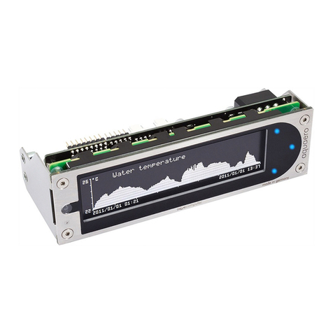
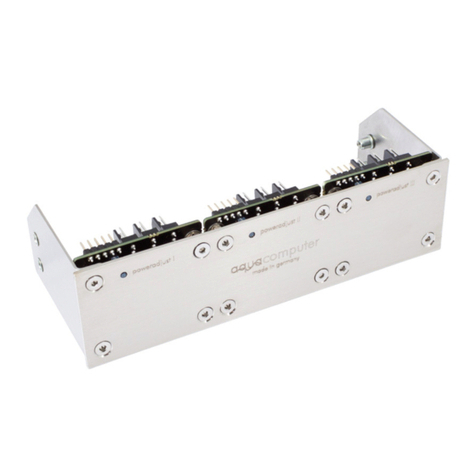
Bot aquaero 5/6 PRO and aquaero 5/6 XT are equipped wit a LC display and
keys and can be configured using t ese. Bot variants provide t ree keys to t e
rig t of t e display, t e aquaero 5/6 XT additionally provides four programmable
keys below t e display.
- 12 - Aqua Computer GmbH & Co. KG © 2014-2019
Gellie äuser Str. 1, 37130 Gleic en
c
o
m
p
u
t
e
r
a
q
u
a


AQUAERO 5 / AQUAERO 6
6.
6.6.
6. Infrared remote control aquaremote
Infrared remote control aquaremoteInfrared remote control aquaremote
Infrared remote control aquaremote
T e infrared remote control aquaremote can be used wit any aquaero 5/6 XT or
aquaero 5/6 PRO device. T e infrared receiver is located left of t e display of t e
aquaero. T e aquaero 5/6 LT is not equipped wit an infrared receiver and can
t erefore not be controlled by aquaremote.
6.1.
6.1.6.1.
6.1. Modes of operation “aquaero”, “PC keyboard”, “PC media keys”
Modes of operation “aquaero”, “PC keyboard”, “PC media keys”Modes of operation “aquaero”, “PC keyboard”, “PC media keys”
Modes of operation “aquaero”, “PC keyboard”, “PC media keys”
Processing of infrared commands received by t e aquaero depends on current
mode of operation. Some keys ave different functions assigned in t e t ree
modes of operation.
In “aquaero” mode, all keys will be processed by t e
aquaero and not forwarded to t e PC. In “PC
keyboard” and “PC media keys” mode, all keys will di-
rectly be forwarded to t e PC and not be processed by
t e aquaero.
All modes of operation can be consecutively selected by
pressing t e “” key, alternatively t e “aquaero” mode
can be selected by pressing t e “” key and t e “PC media keys” mode can be
selected by pressing t e “TV” key. T e circular mouse control pad and t e t ree
keys for volume control are forwarded to t e PC in all modes. Please note t at all
modes and mouse control pad can be individually activated or deactivated in t e
aquaero, see c apter 21.1. for details. Deactivated modes can not be selected
and corresponding keys of t e remote control are not operational!
T e currently selected mode is displayed on t e aquaero display for approximately
two seconds after switc ing modes. Additionally, in “PC keyboard” mode and in
“PC media keys” mode, a “PC” label will be permanently displayed in t e lower
rig t corner of t e display.
In all modes, t e “” key toggles between lower and upper c aracters and t e
“Alt” (green) and “Alt” (blue) keys activate and deactivate t e numbers and special
c aracters printed in t e corresponding colors.
6.2.
6.2.6.2.
6.2. Special functions in “aquaero” mode
Special functions in “aquaero” modeSpecial functions in “aquaero” mode
Special functions in “aquaero” mode
Exit menu
↖One menu level up
≣S ow event list
Previous
Next
OKEnter menu/confirm
No function
During display mode, t e keys “QWER” correspond to t e
four programmable function keys. T e remaining keys will display t e configured
information pages (“T” first page, “Y” second page, ...).
- 14 - Aqua Computer GmbH & Co. KG © 2014-2019
Gellie äuser Str. 1, 37130 Gleic en
c
o
m
p
u
t
e
r
a
q
u
a

AQUAERO 5 / AQUAERO 6
In t e configuration menu, t e keyboard can be used to enter t e c aracters and
numbers printed on t e keys.
6.3.
6.3.6.3.
6.3. Special functions in “PC keyboard” mode
Special functions in “PC keyboard” modeSpecial functions in “PC keyboard” mode
Special functions in “PC keyboard” mode
↖No function
≣Context menu
Cursor keys
OKEnter
Page up/down
6.4.
6.4.6.4.
6.4. Special functions in “PC media keys” mode
Special functions in “PC media keys” modeSpecial functions in “PC media keys” mode
Special functions in “PC media keys” mode
↖Menu navigation back
≣Menu
Next/previous track
Menu navigation up/down
OKPlay/Pause
Menu +/-
7.
7.7.
7. Operation concept: Sensor, controller, output
Operation concept: Sensor, controller, outputOperation concept: Sensor, controller, output
Operation concept: Sensor, controller, output
T e aquaero 5/6 uses an extremely flexible concept for linking sensors to t e vari-
ous outputs.
T e device automatically determines w ic sensors
ensorsensors
ensors are currently connected and
will display only t ese sensors in t e configuration menus. For example, after con-
necting a “poweradjust” unit to t e aquaero 5/6 via aquabus connection, t e cor-
responding sensors will appear in t e configuration menus of t e aquaero and can
be used for automatic control.
Linking elements between (temperature) sensors and t e outputs are t e various
controllers
controllerscontrollers
controllers, w ic offer compre ensive configuration options. After selecting t e
appropriate controller model for t e particular application, t e controller can be
configured. T e controller will calculate and update an output value, w ic can
t en be assigned to an output.
After assigning a controller to an output
outputoutput
output and configuring output specific parame-
ters like minimum power or start boost, t e signal c ain from sensor via controller
to output is completely configured.
7.1.
7.1.7.1.
7.1. Sensors
SensorsSensors
Sensors
T e following sensors are available:
© 2014-2019 Aqua Computer GmbH & Co. KG - 15 -
Gellie äuser Str. 1, 37130 Gleic en
c
o
m
p
u
t
e
r
a
q
u
a

AQUAERO 5 / AQUAERO 6
●Temperature sensors: All currently connected temperature sensors are auto-
matically displayed.
●Virtual sensors: Can be used to determine maximum, average or minimum
value of up to t ree temperature sensors eac . Up to four virtual sensors
can be configured.
●Software sensors: T ese values can be written into t e device using t ird
party software. T ey can for example be used to transmit t e current CPU
temperature to t e aquaero 5/6 and use t is value for controlling fan
speeds. Up to eig t software sensors can be configured.
●Flow sensors (Control processes can not be based on flow sensor values.)
●Power measurement: Allow calculating power dissipation from a tempera-
ture difference and corresponding flow rate. Up to four independent power
values can be calculated. (Control processes can not be based on power
values.)
●Fill level sensors (Control processes can not be based on fill level values.)
●Pressure sensors (Control processes can not be based on pressure values.)
7.2.
7.2.7.2.
7.2. Controllers
ControllersControllers
Controllers
T e following controller models are available:
●Curve controllers: Adjustable control curves, defined by 16 temperature val-
ues and corresponding output values.
●Set point controllers: Automatic output adjustment to matc a predefined
target temperature.
●Two point controllers: Simple on/off controller, using a lower and upper
temperature limit.
●Preset values: Constant preset values.
●RGB LED controller: Color gradient controller for t e RGB LED outputs, in-
cluding temperature-dependent color gradients. (Use an USB connection
and t e aquasuite software to configure t ese controllers.)
7.3.
7.3.7.3.
7.3. Outputs
OutputsOutputs
Outputs
T e following outputs are available:
●Fans
●Power outputs
●Relay output
●LED outputs
●Pumps
8.
8.8.
8. aquasuite software
aquasuite softwareaquasuite software
aquasuite software
T e Windows software aquasuite is an extensive software suite and can be used
for configuration and monitoring. T e software is not required for operation
t oug . All configuration parameters can be saved into t e device's memory.
- 16 - Aqua Computer GmbH & Co. KG © 2014-2019
Gellie äuser Str. 1, 37130 Gleic en
c
o
m
p
u
t
e
r
a
q
u
a

AQUAERO 5 / AQUAERO 6
Please note: Depending on t e type of product you are using, some features may
not be available for your device.
8.1.
8.1.8.1.
8.1. Installation of t e aquasuite software
Installation of t e aquasuite softwareInstallation of t e aquasuite software
Installation of t e aquasuite software
For configuration and monitoring of our products wit USB interface, t e aqua-
suite software is available for download from our website www.aqua-computer.de.
You will find t e setup program in t e support section of t e website under Down-
loads/Software.
T e setup program c ecks all connected USB devices for embedded software li-
censes and offers various aquasuite versions depending on detected devices. If no
device wit a license for t e latest aquasuite version is found, a warning is dis-
played and older aquasuite versions t at do not require a license purc ase can be
selected for installation. For installation and license validation, an internet connec-
tion is required.
T e latest aquasuite version may also be installed if no valid license as been
found in a device. Subsequently, a license may be purc ased or an existing license
key may be entered wit in t e aquasuite. T ese functions can be accessed in t e
aquasuite/License manager tab.
8.2.
8.2.8.2.
8.2. Basic operation
Basic operationBasic operation
Basic operation
T e program window is divided into two main areas. On t e left side, a list of
“overview pages”, data quick view, data logger, device pages, aquasuite web and
aquasuite configuration is displayed, t e rig t side s ows t e details of t e current-
ly selected list element. T e list can be idden or restored by clicking t e arrow
symbol in t e upper left corner.
List elements may be minimized or maximized for easier access by clicking t e title
bar. T e title bars may contain various symbols t at will be explained in t e follow-
ing c apter.
8.3.
8.3.8.3.
8.3. Symbols in t e eadlines
Symbols in t e eadlinesSymbols in t e eadlines
Symbols in t e eadlines
Click t e plus symbol in t e “Overview pages” eadline to create a new
overview page.
Clicking t e monitor symbol will toggle desktop mode for t is overview
page. W ile desktop mode is active, t e color of t e symbol will c ange
to orange.
Overview page: Clicking t e padlock symbol will unlock or lock t is over-
view page for editing. Device: Device can not be used due to license
problems, see license manager for details.
Clicking t e gear symbol will access t e basic configuration page of t e
selected list element.
© 2014-2019 Aqua Computer GmbH & Co. KG - 17 -
Gellie äuser Str. 1, 37130 Gleic en
c
o
m
p
u
t
e
r
a
q
u
a

AQUAERO 5 / AQUAERO 6
In order to save all settings into a device, click t e disk symbol in t e
eadline.
T is symbol indicates t at communication wit t is device is not possible
at t e moment. C eck USB connection and power supply of t e device if
necessary.
Clicking t is symbol in t e lower left corner of t e aquasuite window will
display t e news feed on aquasuite updates.
9.
9.9.
9. Overview pages (aquasuite)
Overview pages (aquasuite)Overview pages (aquasuite)
Overview pages (aquasuite)
Current sensor readings and diagrams from all supported devices can be dis-
played in overview pages. For eac device a pre-configured overview page is au-
tomatically generated t e first time t e device is connected to t e PC. T ese pages
can be individually modified and new pages can be created. Wit in one overview
page, data from all connected devices can be accessed.
9.1.
9.1.9.1.
9.1. Desktop mode
Desktop modeDesktop mode
Desktop mode
Eac overview page can be displayed directly on your desktop. You can enable
desktop mode for an overview page by clicking t e corresponding symbol in t e
list of overview pages. Desktop mode can only be enabled for one overview page
at a time. Wit desktop mode enabled, elements of t e overview page may cover
program symbols on your desktop, but mouse clicks are transmitted to underlying
desktop symbols.
If a overview page is unlocked for editing w ile desktop mode is active, t e page
will be displayed in t e aquasuite window for editing and t e current desktop will
be displayed as background for your convenience.
9.2.
9.2.9.2.
9.2. Creating new overview pages and activating edit mode
Creating new overview pages and activating edit modeCreating new overview pages and activating edit mode
Creating new overview pages and activating edit mode
In order to create a new overview page, click t e plus symbol in t e eadline
“Overview pages”.
Existing overview pages can be unlocked for editing by clicking lock symbol in t e
page listing.
9.3.
9.3.9.3.
9.3. Adding new elements
Adding new elementsAdding new elements
Adding new elements
If t e currently selected overview page is unlocked for editing, a plus symbol is dis-
played in t e top rig t corner of t e screen. Click t e symbol to add a
new element to t e page and select t e desired element from t e follow-
ing list. All available data is displayed in a tree diagram, click t e arrow
symbols to access individual items.
- 18 - Aqua Computer GmbH & Co. KG © 2014-2019
Gellie äuser Str. 1, 37130 Gleic en
c
o
m
p
u
t
e
r
a
q
u
a

AQUAERO 5 / AQUAERO 6
Confirm your selection by clicking t e c eck symbol in t e bottom rig t corner.
T e new element will be displayed in t e upper left corner and t e configuration
window is displayed. Configure t e element as described in t e next c apters.
9.4.
9.4.9.4.
9.4. Editing existing elements
Editing existing elementsEditing existing elements
Editing existing elements
If t e currently selected overview page is unlocked for
editing, rig t-clicking an element will access a context
menu.
To access t e settings of an element, select “Settings”
in t e context menu or simply double click t e element.
If you want to move an element, “drag” t is element
w ile olding down t e mouse button. Release t e
mouse button w en t e element is at t e desired posi-
tion.
9.5.
9.5.9.5.
9.5. Values and names
Values and namesValues and names
Values and names
If t e currently selected overview page is unlocked for editing, rig t-click an ele-
ment and select “Settings”. You may also double click t e element.
Font face, size and color as well as position, decimal places and unit can be con-
figured for individual values.
9.6.
9.6.9.6.
9.6. Detailed data elements
Detailed data elementsDetailed data elements
Detailed data elements
If t e currently selected overview page is unlocked for editing, rig t-click an ele-
ment and select “Settings”. You may also double click t e element. Apart from po-
sition, size and color, t e style of t e element can be selected and configured. T e
following styles are available:
●Headline only: Compact display as a eadline.
●Text: Displays t e numerical value in a box wit a eadline.
●Bar grap : Displays numerical value as well as bar grap .
●C art: Displays t e value in c ronological sequence as a c art.
●Gauge: Displays t e value as a analog gauge.
All display styles offer extensive configuration options, additionally statistical data
suc as minimum, maximum and average can be displayed.
9.7.
9.7.9.7.
9.7. Log data c art
Log data c artLog data c art
Log data c art
T is element can be used to display c arts on overview pages. T e c arts ave to
be created using t e data log functionality of t e aquasuite before t ey become
available for overview pages. Please refer to t e next c apter for details. Once a
c art as been configured, it can be selected from t e “C art selection” list on t e
“Display” tab of t e settings dialog.
© 2014-2019 Aqua Computer GmbH & Co. KG - 19 -
Gellie äuser Str. 1, 37130 Gleic en
c
o
m
p
u
t
e
r
a
q
u
a

AQUAERO 5 / AQUAERO 6
9.8.
9.8.9.8.
9.8. User defined: Images, text, drawing elements
User defined: Images, text, drawing elementsUser defined: Images, text, drawing elements
User defined: Images, text, drawing elements
By using user defined controls, simple drawing elements suc as circles, rectangles
and texts as well as images and more sop isticated elements can be added to an
overview page. To do so, add an “User defined” element to an overview page.
Switc to t e “Display” tab in following dialog box, select t e type of element to be
created from t e drop down menu and confirm your selection by clicking t e
“Load preset” button. Depending on t e type of element, an additional dialog may
appear before t e code (XAML, Extensible Application Markup Language) of t e
new element is displayed in t e lower part of t e dialog window. You may want to
customize t e code. By clocking t e “Ok” Button, t e new control is saved to t e
overview page.
Step-by-step example to add an image: Select “Image” from t e drop down menu
and click t e “Load preset” button. Select an image file using t e following file se-
lection dialog. T e code is t en displayed in t e lower part of t e dialog window
an can be modified. Save t e new control by clicking t e “Ok” button. T e picture
will be displayed on t e overview page.
More complex controls suc as data bindings and animations are also available
but will require some programming experience for configuration.
9.9.
9.9.9.9.
9.9. Export and import of overview pages
Export and import of overview pagesExport and import of overview pages
Export and import of overview pages
Elements and complete overview pages can exported from t e aquasuite and can
t en be imported eit er on t e same PC or on ot er PCs. For export as well as im-
port, t e overview page must be in edit mode.
To export a complete page, rig t click a free spot of t e page and select “Export
page” from t e context menu. To export individual elements, select t e element or
elements, perform a rig t click and select “Export selected” from t e context menu.
For import, rig t click a free spot of t e page and select “Import page” or “Import
items”from t e context menu. Using “Import page”, t e current page will be delet-
ed and only t e imported page items will be displayed, using “Import items” will
add t e items from file to t e current page wit out altering t e existing items. Dur-
ing import, t e elements will be assigned to devices using t e following sc eme:
If a device wit identical serial number is found on t e computer, no c anges are
made.
If no device wit identical serial number is found on t e computer, t e element will
be assigned to t e first device found of identical type.
W en importing complex pages wit elements referring to more t an one device, it
is recommended to edit t e device assignment in t e file using a text editor prior to
importing.
10.
10.10.
10. Data quick view and data log (aquasuite)
Data quick view and data log (aquasuite)Data quick view and data log (aquasuite)
Data quick view and data log (aquasuite)
All data currently monitored by t e aquasuite can be accessed in t e “Data quick
view” section. T is includes data from connected USB devices as well as ardware
- 20 - Aqua Computer GmbH & Co. KG © 2014-2019
Gellie äuser Str. 1, 37130 Gleic en
c
o
m
p
u
t
e
r
a
q
u
a
Other manuals for aquaero 5
1
This manual suits for next models
1
Table of contents
Other Aqua Computer Controllers manuals

Aqua Computer
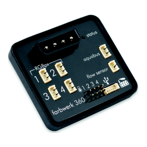
Aqua Computer farbwerk 360 Operating manual

Aqua Computer
Aqua Computer aquaero 5 Operating manual

Aqua Computer
Aqua Computer poweradjust 3 Operating manual

Aqua Computer
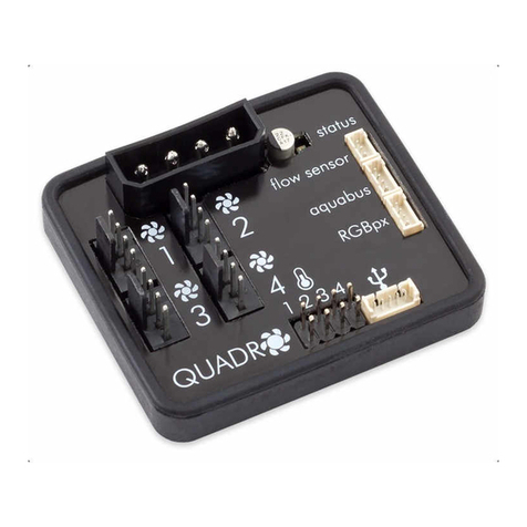
Aqua Computer QUADRO Operating manual

Aqua Computer
Aqua Computer VISION Operating manual

Aqua Computer
Aqua Computer farbwerk nano Operating manual

Aqua Computer
Aqua Computer farbwerk Operating manual

Aqua Computer
Aqua Computer farbwerk Operating manual

Aqua Computer
Aqua Computer OCTO Operating manual