Aqua Computer farbwerk Operating manual

FARBWERK
User and installation manual
User and installation manualUser and installation manual
User and installation manual
farbwerk
farbwerkfarbwerk
farbwerk
Revision 2 / Hardware version 102
Firmware version 1001
a uasuite version 2016
Current as of October 2016
All information contained in this manual is subject to change without prior notice.
All rights reserved.
© 2014-2016 A ua Computer GmbH & Co. KG - 1 -
Gelliehäuser Str. 1, 37130 Gleichen
c
o
m
p
u
t
e
r
a
u
a

FARBWERK
Table of contents
Table of contentsTable of contents
Table of contents
1. Preface.........................................................................................4
2. Safety precautions.........................................................................4
3. Scope of delivery..........................................................................4
4. Assembly instructions.....................................................................4
5. Electrical connections....................................................................5
5.1. Connector overview......................................................................5
5.2. Power supply................................................................................5
5.3. LED output 1-4.............................................................................5
5.4. USB.............................................................................................5
5.5. a uabus 1/2................................................................................6
5.6. Temperature sensors.....................................................................6
6. a uasuite software........................................................................7
6.1. Installation of the a uasuite software...............................................7
6.2. Basic operation............................................................................7
6.3. Symbols in the headlines................................................................7
7. Overview pages (a uasuite)...........................................................8
7.1. Desktop mode..............................................................................8
7.2. Creating new overview pages and activating edit mode....................8
7.3. Adding new elements....................................................................8
7.4. Editing existing elements................................................................9
7.5. Settings of individual values...........................................................9
7.6. Settings of control elements............................................................9
7.7. Custom controls: Images, text, drawing elements............................10
7.8. Log data chart............................................................................10
7.9. Export and import of overview pages.............................................10
8. Data log (a uasuite)...................................................................11
8.1. Log settings................................................................................11
8.2. Analyze data..............................................................................11
8.3. Manual data export.....................................................................12
8.4. Automatic data export.................................................................12
9. Sensor configuration (a uasuite)..................................................13
9.1. Sensor mode..............................................................................13
9.2. Offset........................................................................................13
9.3. Software sensors.........................................................................13
10. Controller configuration(a uasuite)............................................14
10.1. Output mode...........................................................................14
10.2. Color settings...........................................................................15
10.3. Temperature controlled mode....................................................15
10.4. Refresh speed...........................................................................15
10.5. Fading effect............................................................................15
- 2 - A ua Computer GmbH & Co. KG © 2014-2016
Gelliehäuser Str. 1, 37130 Gleichen
c
o
m
p
u
t
e
r
a
u
a

FARBWERK
11. System settings farbwerk (a uasuite)...........................................15
11.1. Device information....................................................................15
11.2. Factory defaults........................................................................15
11.3. a uabus configuration..............................................................15
11.4. Bluetooth configuration (Bluetooth version only)...........................16
12. Basic settings (a uasuite)...........................................................16
12.1. Language................................................................................16
12.2. Units.......................................................................................16
12.3. Application start-up...................................................................16
12.4. Service administration...............................................................16
13. Bluetooth demo app for Android................................................16
13.1. Download and installation.........................................................16
13.2. Bluetooth pairing......................................................................17
13.3. Using the Android demo app.....................................................17
14. Technical details and care instructions........................................17
14.1. Technical details.......................................................................17
14.2. Care instructions.......................................................................18
14.3. Waste disposal.........................................................................18
14.4. Contact A ua Computer............................................................18
© 2014-2016 A ua Computer GmbH & Co. KG - 3 -
Gelliehäuser Str. 1, 37130 Gleichen
c
o
m
p
u
t
e
r
a
u
a

FARBWERK
1. Preface
1. Preface1. Preface
1. Preface
The farbwerk unit is a high power LED controller for PCs.
Considering the fast technical development, we reserve the right to perform alter-
ations to the products at any time. It therefore is possible that your product does
not correspond precisely to the descriptions or illustrations in this manual.
2. Safety precautions
2. Safety precautions2. Safety precautions
2. Safety precautions
The following safety precautions have to be observed at all times:
●Save your data onto suitable media before working on your hardware!
●The farbwerk unit may only be used inside a PC case!
●Never touch electronic components during operation! Do not connect or
disconnect cables to/from the device while the device is powered! Compo-
nents may get very hot during operation. After power off, let the device cool
down for at least 30 minutes before touching it!
●Do not turn the PC on unless you are sure that all cable connections to/from
the farbwerk unit are correctly attached!
●This product is not designed for use in life support appliances, devices, or
systems where malfunction of this product can reasonably be expected to re-
sult in personal injury. A ua Computer GmbH & Co. KG customers using or
selling this product for use in such application do so at their own risk and
agree to fully indemnify A ua Computer GmbH & Co. KG for any damages
resulting from such application!
3. Scope of delivery
3. Scope of delivery3. Scope of delivery
3. Scope of delivery
●One farbwerk controller
●One internal USB cable
●Mounting materials
●This manual
4.
4. 4.
4. Assembly instructions
Assembly instructionsAssembly instructions
Assembly instructions
Use the supplied screws to install the farbwerk controller inside your PC case.
Make sure that the PCB and electronic components do not have contact to metal
parts or other electronic devices inside the PC case, otherwise malfunctions or de-
struction of the farbwerk unit or other devices may occur!
- 4 - A ua Computer GmbH & Co. KG © 2014-2016
Gelliehäuser Str. 1, 37130 Gleichen
c
o
m
p
u
t
e
r
a
u
a

FARBWERK
5.
5. 5.
5. Electrical connections
Electrical connectionsElectrical connections
Electrical connections
5.1. Connector overview
5.1. Connector overview5.1. Connector overview
5.1. Connector overview
ATTENTION: Completely turn off your power supply or disconnect the mains pow-
er cord from the wall outlet before connecting or disconnecting any cables to/from
the device!
Please refer to the following chapters for details on the individual connectors.
5.2. Power supply
5.2. Power supply5.2. Power supply
5.2. Power supply
Connect a power plug of your PC's power supply unit to this connector. Do not
use excessive force but double check the polarity of the plug if you are having
trouble to connect.
Pin assignment: Pin 1: +12 V
Pin 2: GND
Pin 3: GND
Pin 4: +5 V
5.3. LED output 1-4
5.3. LED output 1-45.3. LED output 1-4
5.3. LED output 1-4
Connect up to four RGB LED strips to these outputs. Maximum current rating for
each separate color is 2.5 A at 12 V (corresponding to 30 Watts) and a total max-
imum combined current of 8 A at 12 V for all twelve color channels (correspond-
ing to 96 Watts total).
The LED output are not short-circuit proof!
Pin assignment: Pin 1: +12 V
Pin 2: GND blue
Pin 3: GND red
Pin 3: GND green
5.4. USB
5.4. USB5.4. USB
5.4. USB
This connector is used for USB communication to the PC and for power supply.
Connect to an internal USB header of your motherboard. Take special care to
make sure the pin alignment matches your motherboard!
© 2014-2016 A ua Computer GmbH & Co. KG - 5 -
Gelliehäuser Str. 1, 37130 Gleichen
c
o
m
p
u
t
e
r
a
u
a

FARBWERK
Pin assignment: Pin 1: +5 V(red)
Pin 2: D- (white)
Pin 3: D+ (green)
Pin 4: GND(black)
Pin 5: not connected
5.5. a uabus 1/2
5.5. a uabus 1/25.5. a uabus 1/2
5.5. a uabus 1/2
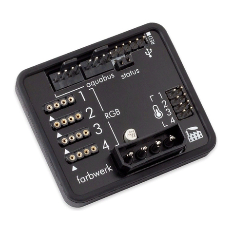
Connector for communication with other A ua Computer devices. Use a compati-
ble a uabus cable (not included in delivery, article no. 53122/53162) to connect
the farbwerk controller board to a suitable connector of a compatible device, for
example an a uaero. USB and a uabus interface can be used at the same time.
Pin assignment: Pin 1: GND
Pin 2: SDA
Pin 3: SCL
Compatible a uabus devices:
●a uaero 6 XT/PRO/LT (art. 53206, 53146, 53145, 53234)
●a uaero 5 XT/PRO/LT (art. 53125, 53095, 53090, 53089)
5.6. Temperature sensors
5.6. Temperature sensors5.6. Temperature sensors
5.6. Temperature sensors
Connector for up to four temperature sensor.
Pin assignment: Pin 1/3/5/7: Signal 1-4
Pin 2/4/6/8: GND
Compatible sensors:
●Temperature sensor inline G1/4 (art. 53066)
●Temperature sensor inner/outer thread G1/4 (art. 53067)
●Temperature sensor G1/4 (art. 53147)
●Temperature sensor plug&cool (art. 53025)
●Temperature sensor 70 cm (art. 53026)
- 6 - A ua Computer GmbH & Co. KG © 2014-2016
Gelliehäuser Str. 1, 37130 Gleichen
c
o
m
p
u
t
e
r
a
u
a

FARBWERK
6. a uasuite software
6. a uasuite software6. a uasuite software
6. a uasuite software
The Windows software a uasuite is an extensive software suite and can be used
for configuration and monitoring. The software is not re uired for operation
though. All configuration parameters can be saved into the device's memory, so
after initial configuration, LED color can for example be controlled depending on
a temperature sensor reading independently from an USB or a uabus connection.
Please note: Depending on the type of product you are using, some features may
not be available for your device.
6.1. Installation of the a uasuite software
6.1. Installation of the a uasuite software6.1. Installation of the a uasuite software
6.1. Installation of the a uasuite software
For configuration and monitoring of farbwerk units, the a uasuite software is
available for download from our website www.a ua-computer.de. You will find the
most up-to-date version in the support section of the website.
After downloading, install the a uasuite software. Depending on your selection
during the installation process, the a uasuite software may start automatically
upon restart or may be accessed through a symbol on your desktop or in the start
menu.
6.2. Basic operation
6.2. Basic operation6.2. Basic operation
6.2. Basic operation
The program window is divided into two main areas. On the left side, a list of
“overview pages”, data logger, device pages and the basic configuration page of
the software is displayed, the right side shows the details of the currently selected
list element. The list can be hidden or restored by clicking the arrow symbol in the
upper left corner.
List elements may be minimized or maximized for easier access by clicking the title
bar. The title bars may contain various symbols that will be explained in the follow-
ing chapter.
6.3.
6.3. 6.3.
6.3. Symbols in the headlines
Symbols in the headlinesSymbols in the headlines
Symbols in the headlines
Click the plus symbol in the “Overview pages” headline to create a new
overview page.
Clicking the monitor symbol will toggle desktop mode for this overview
page. While desktop mode is active, the arrow in the symbol will have
an orange color.
Clicking the padlock symbol will unlock or lock this overview page for
editing.
Clicking the gear wheel symbol will access the basic configuration page
of the selected list element.
© 2014-2016 A ua Computer GmbH & Co. KG - 7 -
Gelliehäuser Str. 1, 37130 Gleichen
c
o
m
p
u
t
e
r
a
u
a

FARBWERK
In order to save all settings into a device, click the disk symbol in the
headline.
This symbol indicates that communication with this device is not possible
at the moment. Check USB connection and power supply of the device if
necessary.
Clicking this symbol in the lower left corner of the a uasuite window will
display the news feed on a uasuite updates.
7. Overview pages (a uasuite)
7. Overview pages (a uasuite)7. Overview pages (a uasuite)
7. Overview pages (a uasuite)
Current sensor readings and diagrams from all supported devices can be dis-
played in overview pages. For each device a pre-configured overview page is au-
tomatically generated the first time the device is connected to the PC. These pages
can be individually modified and new pages can be created. Within one overview
page, data from all connected devices can be accessed.
7.1. Desktop mode
7.1. Desktop mode7.1. Desktop mode
7.1. Desktop mode
Each overview page can be displayed directly on your desktop. You can enable
desktop mode for an overview page by clicking the corresponding symbol in the
list of overview pages. Desktop mode can only be enabled for one overview page
at a time. With desktop mode enabled, elements of the overview page may cover
program symbols on your desktop, but mouse clicks are transmitted to underlying
desktop symbols.
If a overview page is unlocked for editing while desktop mode is active, the page
will be displayed in the a uasuite window for editing and the current desktop will
be displayed as background for your convenience.
7.2. Creating new overview pages and activating edit mode
7.2. Creating new overview pages and activating edit mode7.2. Creating new overview pages and activating edit mode
7.2. Creating new overview pages and activating edit mode
In order to create a new overview page, click the plus symbol in the headline
“Overview pages”. Existing overview pages can be unlocked for editing by clicking
lock symbol in the page listing.
7.3. Adding new elements
7.3. Adding new elements7.3. Adding new elements
7.3. Adding new elements
If the currently selected overview page is unlocked for editing, a white plus symbol
is displayed in the bottom right corner of the screen. Click the symbol to
add a new element to the page and select the desired element from the
following list.
- 8 - A ua Computer GmbH & Co. KG © 2014-2016
Gelliehäuser Str. 1, 37130 Gleichen
c
o
m
p
u
t
e
r
a
u
a

FARBWERK
All available elements are dis-
played in a tree diagram, click
the arrow or plus and minus
symbols to access individual
items. Please note that individ-
ual values can be selected as
well as higher-ranking control
elements. Custom controls
can be selected for example
to import image files.
Confirm your selection by
clicking “OK”. The new ele-
ment will be displayed in the
upper left corner and the con-
figuration window is dis-
played. Configure the element
as described in the next chap-
ters.
7.4. Editing existing elements
7.4. Editing existing elements7.4. Editing existing elements
7.4. Editing existing elements
If the currently selected overview page is unlocked for editing, right-clicking an ele-
ment will access a context menu. To access the settings of an element, select “Set-
tings” in the context menu or simply double click the element. If you want to move
an element, “drag” this element while holding down the mouse button. Release
the mouse button when the element is at the desired position.
7.5. Settings of individual values
7.5. Settings of individual values7.5. Settings of individual values
7.5. Settings of individual values
If the currently selected overview page is unlocked for editing, right-click an ele-
ment and select “Settings”. You may also double click the element.
Font face, size and color as well as position, decimal places and unit can be con-
figured for individual values.
7.6. Settings of control elements
7.6. Settings of control elements7.6. Settings of control elements
7.6. Settings of control elements
If the currently selected overview page is unlocked for editing, right-click an ele-
ment and select “Settings”. You may also double click the element. Apart from po-
sition, size and color, the style of the element can be selected and configured. The
following styles are available:
●Headline only: Compact display as a headline.
●Text: Displays the numerical value in a box with a headline.
●Bar graph: Displays numerical value as well as bar graph.
●Chart: Displays the value in chronological se uence as a chart.
●Gauge: Displays the value as a analog gauge.
© 2014-2016 A ua Computer GmbH & Co. KG - 9 -
Gelliehäuser Str. 1, 37130 Gleichen
c
o
m
p
u
t
e
r
a
u
a

FARBWERK
All display styles offer extensive configuration options, additionally statistical data
such as minimum, maximum and average can be displayed.
7.7. Custom controls: Images, text, drawing elements
7.7. Custom controls: Images, text, drawing elements7.7. Custom controls: Images, text, drawing elements
7.7. Custom controls: Images, text, drawing elements
By using custom controls, simple drawing elements such as circles, rectangles and
texts as well as images and more sophisticated elements can be added to an over-
view page. To do so, add a “Custom control” to an overview page. Switch to the
“Display” tab in following dialog box, select the type of element to be created from
the drop down menu and confirm your selection by clicking the “Load preset” but-
ton. Depending on the type of element, an additional dialog may appear before
the code (XAML, Extensible Application Markup Language) of the new element is
displayed in the lower part of the dialog window. You may want to customize the
code. By clocking the “Ok” Button, the new control is saved to the overview page.
Example process to add an image: Select “Image” from the drop down menu and
click the “Load preset” button. Select an image file using the following file selec-
tion dialog. The code is then displayed in the lower part of the dialog window an
can be modified. Save the new control by clicking the “Ok” button. The picture
will be displayed on the overview page.
More complex controls such as data bindings and animations are also available
but will re uire some programming experience for configuration.
7.8. Log data chart
7.8. Log data chart7.8. Log data chart
7.8. Log data chart
This element can be used to display charts on overview pages. The charts have to
be created and saved using the data log functionality of the a uasuite before they
become available for overview pages. Please refer to the next chapter for details.
Once a chart has been configured, it can be selected from the “Chart selection”
list on the “Display” tab of the settings dialog.
7.9. Export and import of overview pages
7.9. Export and import of overview pages7.9. Export and import of overview pages
7.9. Export and import of overview pages
Elements and complete overview pages can exported from the a uasuite and can
then be imported either on the same PC or on other PCs. For export as well as im-
port, the overview page must be in edit mode.
To export a complete page, right click a free spot of the page and select “Export
page” from the context menu. To export individual elements, select the element or
elements, perform a right click and select “Export selected” from the context menu.
For import, right click a free spot of the page and select “Import page” or “Import
items”from the context menu. Using “Import page”, the current page will be delet-
ed and only the imported page items will be displayed, using “Import items” will
add the items from file to the current page without altering the existing items. Dur-
ing import, the elements will be assigned to devices using the following scheme:
●If a device with identical serial number is found on the computer, no
changes are made.
- 10 - A ua Computer GmbH & Co. KG © 2014-2016
Gelliehäuser Str. 1, 37130 Gleichen
c
o
m
p
u
t
e
r
a
u
a

FARBWERK
●If no device with identical serial number is found on the computer, the ele-
ment will be assigned to the first device found of identical type.
When importing complex pages with elements referring to more than one device, it
is recommended to edit the device assignment in the file using a text editor prior to
importing.
8. Data log (a uasuite)
8. Data log (a uasuite)8. Data log (a uasuite)
8. Data log (a uasuite)
Data from all connected A ua Computer devices can be logged by the a uasuite.
Logged data can then be analyzed by creating charts or be exported to files.
8.1. Log settings
8.1. Log settings8.1. Log settings
8.1. Log settings
The log settings can be accessed by clicking the “Log settings” element below the
“Data log” headline in the listing. To log data, create a new log data set by click-
ing the plus symbol in the upper right corner of the settings window. Enter name,
time interval and configure automatic deletion of old data to meet your re uire-
ments. You may then add the data sources to log by clicking the plus symbol in
the “Data sources” window section. You may add an unlimited number of data
sources to each log data set, the total number of log data sets is also unlimited.
8.2. Analyze data
8.2. Analyze data8.2. Analyze data
8.2. Analyze data
Logged data can be visually evaluated as charts. To do so, select “Analyze data”
below the “Data log” headline in the listing. The chart will initially be empty, di-
rectly below the chart are eight buttons to modify the chart. In the lower section of
the window, the chart data can be configured.
To add data to the chart, first select the “Data sources” tab in the chart configura-
tion and select a data set to be displayed. If no data sources are available, you
will have to configure the log settings as described in the corresponding chapter of
this manual. Select the time period to be displayed on the right side of the window
and add the data to the chart by clicking the “Add data to chart” button. Repeat
this procedure if you want to display more than one data set in the chart.
You may modify the chart using the “Chart setup” and “Data series setup” tabs.
Finally, you can use the “Chart manager” tab to save the current chart configura-
tion and to load or delete previously saved configurations. All saved chart configu-
rations will be available on overview pages for the “Log data chart” element.
The currently displayed chart can be edited by using the buttons directly below the
chart and may also be saved as an image file. The button corresponding to the
currently selected function is highlighted by an orange frame. Please refer to the
following list for details on each function:
To save the currently displayed chart as an image file, click the floppy
disk symbol and select a name and location in the following dialog.
© 2014-2016 A ua Computer GmbH & Co. KG - 11 -
Gelliehäuser Str. 1, 37130 Gleichen
c
o
m
p
u
t
e
r
a
u
a

FARBWERK
This function can be used to add horizontal lines to the chart. While this
function is activated, simply click into the chart to add a line at the cur-
rent cursor position.
This function can be used to add vertical lines to the chart. While this
function is activated, simply click into the chart to add a line at the cur-
rent cursor position.
This function can be used to add annotations to the chart. While this
function is activated, simply click into the chart to add an annotation at
the current cursor position. By clicking into the text box, you may edit the
text. You may also drag the little circle beside the text box to move the connecting
line to the desired position. Use drag and drop to move existing annotations.
This function can be used to remove lines or annotations from the chart.
While this function is activated, simply click the element to be removed.
This function can be used to move the visible portion of the chart. Press
and hold the mouse button while moving the cursor in the chart to select
the position to be displayed, then release the button.
This function can be used to zoom in and out. Use the mouse wheel or
select the area to be displayed. You can reset the zoom settings by dou-
ble-clicking in the chart area.
This function will completely remove the chart.
8.3. Manual data export
8.3. Manual data export8.3. Manual data export
8.3. Manual data export
Saved data can be exported from the data log into a XML file. To do so, select
“Analyze data” below the “Data log” headline in the listing. Select the “Data
sources” tab in the chart configuration and select a data set to be exported. If no
data sources are available, you will have to configure the log settings as described
in the corresponding chapter of this manual. Select the time period to be exported
on the right side of the window and start the export process by clicking the “Export
data” button. Enter a file name and path in the following dialog window.
8.4. Automatic data export
8.4. Automatic data export8.4. Automatic data export
8.4. Automatic data export
The automatic data export feature can be used to save data from the a uasuite
into an XML file on the hard disk or in the RAM („memory mapped file“) in a regu-
lar time interval. The automatic data export will always overwrite the previously
saved data, so the file always contains only the most recent data set. Select “Auto-
matic data export” below the “Data log” headline in the listing to access the set-
tings screen. Create a new export data set by clicking the plus symbol in the upper
right corner of the screen. Enter name, path and time interval to meet your re-
uirements. You may then add the data sources to log by clicking the plus symbol
in the “Data sources” window section. You may add an unlimited number of data
- 12 - A ua Computer GmbH & Co. KG © 2014-2016
Gelliehäuser Str. 1, 37130 Gleichen
c
o
m
p
u
t
e
r
a
u
a

FARBWERK
sources to each export data set, the total number of export data sets is also unlim-
ited.
9. Sensor configuration (a uasuite)
9. Sensor configuration (a uasuite)9. Sensor configuration (a uasuite)
9. Sensor configuration (a uasuite)
Select “Sensors” from the device list for the device to be configured.
9.1. Sensor mode
9.1. Sensor mode9.1. Sensor mode
9.1. Sensor mode
Select the desired mode of operation for the sensor input. If “Temperature” mode
is selected, temperature will be calculated from the sensor data. Alternatively, each
input can be configured to “Resistance” or “Voltage 0-3.3 V” mode, resulting in
sensor readings being interpreted as resistance or voltage values.
9.2. Offset
9.2. Offset9.2. Offset
9.2. Offset
If you detect inaccuracies in the temperature sensor readings, you can make cor-
rections here. In general, this should not be necessary. This setting is available in
sensor mode “Temperature” only.
9.3. Software sensors
9.3. Software sensors9.3. Software sensors
9.3. Software sensors
Four available software temperature sensors can be used to transfer temperature
sensor readings from third party software into the farbwerk. Three procedures are
implemented:
1. Sensor data is transmitted from an a uaero 5/6 connected to the farbwerk
via a uabus.
2. A third party software provides data, the “A ua Computer Service” reads
this data and transmits it to the farbwerk via USB connection. This re uires
the third party software to be installed, configured and running as well as
the “A ua Computer Service” to be installed and active.
3. A third party software directly transmits data to the farbwerk via USB connec-
tion. This re uires the third party software to be installed, configured and
running.
Currently, the “A ua Computer Service” supports data transfer from „HWiNFO“
(REALiX, Freeware, www.hwinfo.com), „Open Hardware Monitor“ (Open Hard-
ware Monitor Project, Open Source/MPL 2.0, www.openhardwaremonitor.org)
and „AIDA64“ (FinalWire Ltd., subject to license fees, www.aida64.com).
HWiNFO and Open Hardware Monitor automatically export all temperature sen-
sor values and do not need to be configured.
© 2014-2016 A ua Computer GmbH & Co. KG - 13 -
Gelliehäuser Str. 1, 37130 Gleichen
c
o
m
p
u
t
e
r
a
u
a

FARBWERK
In the AIDA64 preferences menu, writing to WMI must be activated in the „external
applications“ sub-menu:
After activating “Use sensor with A ua Computer Service” in the a uasuite, click
the “Select data source” button to assign the currently selected software sensor to
a temperature sensor provided by third party software.
Software sensor values will only be available while all involved programs are run-
ning, so no data will be available while the operation system is starting up or shut-
ting down or if an involved program is closed. If no data is available or the data
has not been updated within the time interval defined as “Timeout in s”, the
a uaero will use the “Fallback temperature” instead. As soon as data is available
again, normal operation of the software sensor will resume automatically.
10. Controller configuration(a uasuite)
10. Controller configuration(a uasuite)10. Controller configuration(a uasuite)
10. Controller configuration(a uasuite)
Select “Controller” from the device list to configure the four LED outputs.
10.1. Output mode
10.1. Output mode10.1. Output mode
10.1. Output mode
Each RGB output can be controlled by a temperature sensor input or software
temperature sensor, by an external controller (for instance from an a uaero 5/6
connected via a uabus, via Bluetooth connection or third party software), set to a
fixed color or a color gradient. A copy function can be used to transfer all settings
from another previously configured controller.
- 14 - A ua Computer GmbH & Co. KG © 2014-2016
Gelliehäuser Str. 1, 37130 Gleichen
c
o
m
p
u
t
e
r
a
u
a

FARBWERK
10.2. Color settings
10.2. Color settings10.2. Color settings
10.2. Color settings
Depending on the current controller mode, one or two colors can be defined. Col-
ors can conveniently be set using the graphical color and brightness selectors, al-
ternatively corresponding values can be set manually. The “Optimized colors for
A ua Computer LED strip” function enables color optimization for the LED strips
available from A ua Computer.
10.3. Temperature controlled mode
10.3. Temperature controlled mode10.3. Temperature controlled mode
10.3. Temperature controlled mode
In temperature controlled mode, two colors can be defined corresponding to two
temperature readings. The farbwerk controller generates a color gradient for tem-
perature sensor values between these limits. The “Controller source low pass filter”
setting influences sensor reading smoothing for a steady color gradient.
10.4. Refresh speed
10.4. Refresh speed10.4. Refresh speed
10.4. Refresh speed
The “Refresh speed” setting determines how often the controller is updated.
10.5. Fading effect
10.5. Fading effect10.5. Fading effect
10.5. Fading effect
For some controller modes, a fading effect can be activated. By defining the eight
points of the effect curve, a pulsating brightness of the corresponding LED output
can be set.
11. System settings farbwerk (a uasuite)
11. System settings farbwerk (a uasuite)11. System settings farbwerk (a uasuite)
11. System settings farbwerk (a uasuite)
Select “System” from the device list for the device to be configured.
11.1. Device information
11.1. Device information11.1. Device information
11.1. Device information
The details displayed here might be re uired when you contact our service for sup-
port.
11.2. Factory defaults
11.2. Factory defaults11.2. Factory defaults
11.2. Factory defaults
Click the button “Reset device to factory defaults” for a complete reset of all set-
tings. You will have to completely reconfigure the device after resetting it to factory
defaults!
11.3.
11.3. 11.3.
11.3. a uabus configuration
a uabus configurationa uabus configuration
a uabus configuration
Before connecting farbwerk devices to an a uaero 5/6 controller, each farbwerk
device has to be configured to an individual a uabus address. You may skip this
step if only one farbwerk device is connected. Addresses 20 and 21 are available
for farbwerk devices.
© 2014-2016 A ua Computer GmbH & Co. KG - 15 -
Gelliehäuser Str. 1, 37130 Gleichen
c
o
m
p
u
t
e
r
a
u
a

FARBWERK
All farbwerk outputs to be controlled by the a uaero must be configured to use an
“External controller source (a uabus, Bluetooth, USB)” within the farbwerk con-
troller configuration. This re uires a (temporary) USB connection between PC and
farbwerk controller.
11.4. Bluetooth
11.4. Bluetooth11.4. Bluetooth
11.4. Bluetooth configuration (Bluetooth version only)
configuration (Bluetooth version only) configuration (Bluetooth version only)
configuration (Bluetooth version only)
For initializing a Bluetooth connection, a pairing key is re uired. The factory preset
of “1234” can be changed to another four-digit pairing key.
Please note: After changing the pairing key, you will have to power down the farb-
werk device for changes to take effect.
12. Basic settings (a uasuite)
12. Basic settings (a uasuite)12. Basic settings (a uasuite)
12. Basic settings (a uasuite)
Click the entry „Settings“ below the headline „a uasuite“ to access basic settings
for language, units and start-up of the software.
12.1. Language
12.1. Language12.1. Language
12.1. Language
Select a language from the drop down menu. After changing the language setting,
the software will have to be restarted.
12.2. Units
12.2. Units12.2. Units
12.2. Units
Select the units to be used for temperature and flow values from the drop down
menus. After changing these settings, the software will have to be restarted.
12.3. Application start-up
12.3. Application start-up12.3. Application start-up
12.3. Application start-up
You may customize start-up behavior to suit your preferences. You may also select
to hide the task bar symbol of the software when minimized.
12.4. Service administration
12.4. Service administration12.4. Service administration
12.4. Service administration
The service (background service) configures special USB settings for all connected
A ua Computer devices and should therefore always be active.
13. Bluetooth demo app for Android
13. Bluetooth demo app for Android13. Bluetooth demo app for Android
13. Bluetooth demo app for Android
13.1. Download and installation
13.1. Download and installation13.1. Download and installation
13.1. Download and installation
A free demo app is available for download. In order to install the app, you will
have to enable installation from unknown sources. Open the app drawer and go
to “Settings”. In the settings screen, select “Security” and enable “Unknown
sources” from the “Device Administration” section.
- 16 - A ua Computer GmbH & Co. KG © 2014-2016
Gelliehäuser Str. 1, 37130 Gleichen
c
o
m
p
u
t
e
r
a
u
a

FARBWERK
Use the internet browser on your mobile Android device to download the app. You
will find the app on the A ua Computer website www.a ua-computer.de by navi-
→ →gating to “Support” “Downloads” “Software” and selecting the farbwerk Blue-
tooth app for Android.
Open the app drawer and go to “Downloads”. Start the installation by tapping on
the downloaded farbwerk APK file.
We recommend to disable the “Unknown sources” setting after installation for se-
curity reasons.
13.2. Bluetooth pairing
13.2. Bluetooth pairing13.2. Bluetooth pairing
13.2. Bluetooth pairing
Before the farbwerk demo app can access farbwerk devices via Bluetooth, each
farbwerk device must be paired with your mobile device. Open the app drawer
and go to “Settings”. In the settings screen, select “Bluetooth”. The farbwerk Blue-
tooth devices will show as “farbwerk xxxxx-xxxxx”, where xxxxx-xxxxx will be re-
placed by the individual serial number of each farbwerk device. See chapter 11.1.
for reference.
Tap the farbwerk device you want to pair to your mobile phone and enter the pair-
ing key for the farbwerk device. Factory default key is “1234”, see chapter 11.4.
for individual configuration.
13.3. Using the Android demo app
13.3. Using the Android demo app13.3. Using the Android demo app
13.3. Using the Android demo app
Open the app drawer and go to “farbwerk”. The farbwerk demo app will display a
list of all paired farbwerk devices. Tap any device to access the settings for this de-
vice.
Please note: Each output has to be configured to use an “External controller
source” to accept configuration via Bluetooth. Please see chapter 10.1. for refer-
ence.
Please note: Only one mobile device can be connected to a farbwerk device via
Bluetooth at any given time. After leaving the settings screen in the farbwerk demo
app, other devices can connect to this controller via Bluetooth again.
14. Technical details and care instructions
14. Technical details and care instructions14. Technical details and care instructions
14. Technical details and care instructions
14.1. Technical details
14.1. Technical details14.1. Technical details
14.1. Technical details
Dimensions W x H x D: 47 mm x 41 mm x 20 mm
Power supply voltage: 12 V DC ±5 %, 5 V DC ±5 %
Power supply current: max 8.1 A
LED output voltage: 12 V
Output current per channel: max. 2.5 A at 12 V
Combined output current: max. 8 A at 12 V
Ambient temperature range: 10 to 40 °C (noncondensing)
© 2014-2016 A ua Computer GmbH & Co. KG - 17 -
Gelliehäuser Str. 1, 37130 Gleichen
c
o
m
p
u
t
e
r
a
u
a

FARBWERK
Bluetooth interface Bluetooth class 1, max. 10 m, SPP protocol
(Bluetooth version only)
14.2. Care instructions
14.2. Care instructions14.2. Care instructions
14.2. Care instructions
Use a dry and soft cloth for cleaning. All electronic components and headers must
not get in contact with coolant or water!
14.3. Waste disposal
14.3. Waste disposal14.3. Waste disposal
14.3. Waste disposal
This device has to be disposed of as electronic waste. Please check
your local regulations for disposal of electronic waste.
14.4. Contact A ua Computer
14.4. Contact A ua Computer14.4. Contact A ua Computer
14.4. Contact A ua Computer
We are always happy to answer uestions regarding our products and to receive
feedback. For answers on fre uently asked uestions, please also check our web-
site www.a ua-computer.de. You might also want to visit our forums and discuss
our products with experienced moderators and thousands of members – available
24/7. To get in direct contact with our customer support team, we offer several
options:
email: support@a ua-computer.de
Address: A ua Computer GmbH & Co. KG
Gelliehäuser Str. 1
37130 Gleichen, Germany
Tel: +49 (0) 5508 9749290 (9-16 h Central European Time)
Fax: +49 (0) 5508 9749291
- 18 - A ua Computer GmbH & Co. KG © 2014-2016
Gelliehäuser Str. 1, 37130 Gleichen
c
o
m
p
u
t
e
r
a
u
a

FARBWERK
© 2014-2016 A ua Computer GmbH & Co. KG - 19 -
Gelliehäuser Str. 1, 37130 Gleichen
c
o
m
p
u
t
e
r
a
u
a

FARBWERK
94479
- 20 - A ua Computer GmbH & Co. KG © 2014-2016
Gelliehäuser Str. 1, 37130 Gleichen
c
o
m
p
u
t
e
r
a
u
a
Other manuals for farbwerk
1
Table of contents
Other Aqua Computer Controllers manuals

Aqua Computer
Aqua Computer aquaero 5 Operating manual

Aqua Computer
Aqua Computer farbwerk 360 Operating manual

Aqua Computer
Aqua Computer poweradjust 3 Operating manual

Aqua Computer
Aqua Computer farbwerk nano Operating manual

Aqua Computer
Aqua Computer QUADRO Operating manual

Aqua Computer
Aqua Computer farbwerk Operating manual

Aqua Computer
Aqua Computer OCTO Operating manual

Aqua Computer
Aqua Computer aquaero 5 Operating manual

Aqua Computer
Aqua Computer VISION Operating manual