Aqua Computer aquaero 5 Operating manual

AQUAERO 5/6
User and installation manual
User and installation manualUser and installation manual
User and installation manual
aquaero 5
aquaero 6
The information contained in this manual is subject to change without rior
notice. All rights reserved.
Current as of A ril 2014
© 2014 Aqua Com uter GmbH & Co. KG - 1 -
Gelliehäuser Str. 1, 37130 Gleichen
ENGLISH: PAGE 1
DEUTSCH: SEITE 49
c
o
m
u
t
e
r
a
q
u
a

AQUAERO 5/6
Table of contents
Table of contentsTable of contents
Table of contents
1. Sco e of delivery..................................................................................6
2. Preface................................................................................................6
3. Safety recautions................................................................................6
4. Electrical connectors.............................................................................7
4.1. Connector overview...............................................................................7
4.2. Connector “Power”...............................................................................8
4.3. Connector “Fan 1/2/3/4”......................................................................8
4.4. Connector “PWM 1/2”..........................................................................9
4.5. Connector „IR LED“...............................................................................9
4.6. Connector “aquabus low s eed/high s eed”.........................................10
4.7. Connector „RPM/Tacho“.....................................................................10
4.8. Connector „Sensors“...........................................................................11
4.9. Connector „USB“................................................................................11
4.10. Connector „Flow“.............................................................................11
4.11. Connector „RGB LED“.......................................................................11
4.12. Connector „Relay“............................................................................12
4.13. Connector „Standby“ (aquaero 5 only)................................................12
4.14. Com atible o tional accessories for the aquaero 5/6...........................12
5. O eration of the aquaero 5/6 device..................................................13
5.1. O eration via USB connection.............................................................13
5.2. O eration without USB connection.......................................................14
5.3. O eration via keys and dis lay (aquaero 5/6 PRO and XT only)...............14
5.4. O eration via aquaremote (aquaero 5/6 PRO and XT only)....................14
5.5. Configuration menu (aquaero 5/6 PRO and XT only)..............................15
6. Infrared remote control aquaremote....................................................15
6.1. Modes of o eration “aquaero”, “PC keyboard”, “PC media keys”............15
6.2. S ecial functions in “aquaero” mode....................................................16
6.3. S ecial functions in “PC keyboard” mode..............................................17
6.4. S ecial functions in “PC media keys” mode...........................................17
7. O eration conce t: Sensor, controller, out ut......................................17
7.1. Sensors..............................................................................................17
7.2. Controllers.........................................................................................18
7.3. Out uts.............................................................................................18
8. aquasuite software.............................................................................19
8.1. Installation of the aquasuite software.....................................................19
8.2. Basic o eration...................................................................................19
8.3. Symbols in the headlines......................................................................19
9. Overview ages (aquasuite)................................................................20
9.1. Deskto mode....................................................................................20
9.2. Creating new overview ages and activating edit mode...........................21
- 2 - Aqua Com uter GmbH & Co. KG © 2014
Gelliehäuser Str. 1, 37130 Gleichen
c
o
m
u
t
e
r
a
q
u
a

AQUAERO 5/6
9.3. Adding new elements...........................................................................21
9.4. Editing existing elements......................................................................21
9.5. Settings of individual values..................................................................22
9.6. Settings of control elements..................................................................22
9.7. Custom controls: Images, text, drawing elements....................................22
9.8. Log data chart....................................................................................23
9.9. Ex ort and im ort of overview ages.....................................................23
10. Data log (aquasuite).........................................................................23
10.1. Log settings......................................................................................24
10.2. Analyze data.....................................................................................24
10.3. Manual data ex ort...........................................................................25
10.4. Automatic data ex ort.......................................................................26
11. Sensor configuration (aquasuite/device menu)....................................26
11.1. Tem erature sensors..........................................................................26
11.2. Virtual tem erature sensors................................................................26
11.3. Software tem erature sensors.............................................................27
11.4. Flow sensors.....................................................................................28
11.5. Power measurement..........................................................................29
11.6. Fill level sensors................................................................................29
11.7. Pressure sensors................................................................................30
12. Controller configuration (aquasuite/device menu)...............................30
12.1. Curve controllers...............................................................................30
12.2. Set oint controllers...........................................................................31
12.3. Two oint controllers.........................................................................31
12.4. Preset values.....................................................................................31
12.5. RGB LED controller...........................................................................31
13. Fan configuration (aquasuite/device menu)........................................32
13.1. Minimum and maximum ower..........................................................32
13.2. Power, s eed or PWM controlled mode...............................................32
13.3. Start boost and out ut settings............................................................32
13.4. Programmable fuses..........................................................................33
14. Out ut configuration (aquasuite/device menu)...................................33
14.1. LED out uts......................................................................................33
14.2. Power out uts...................................................................................34
14.3. Switching out uts and relays...............................................................34
15. Pum configuration (aquasuite/device menu).....................................34
15.1. aquastream XT..................................................................................35
15.2. D5 um s connected via aquabus......................................................35
16. User interface configuration (aquasuite/device menu, aquaero 5/6
XT/PRO only)..................................................................................35
16.1. Language setting...............................................................................35
16.2. Dis lay settings.................................................................................36
© 2014 Aqua Com uter GmbH & Co. KG - 3 -
Gelliehäuser Str. 1, 37130 Gleichen
c
o
m
u
t
e
r
a
q
u
a

AQUAERO 5/6
16.3. Key settings......................................................................................36
16.4. Programmable function keys (device menu of aquaero 5/6 XT only)........36
17. Information age configuration (aquasuite/device menu, aquaero 5/6
XT/PRO only)..................................................................................36
17.1. Screenshot function (aquasuite only)....................................................37
17.2. S ecial ages and logo (aquasuite only)..............................................37
17.3. Information ages.............................................................................37
17.4. USB LCD age.................................................................................37
18. Alarm actions (aquasuite/device menu)..............................................38
18.1. Alarm su ression after ower on.......................................................38
18.2. Alarm levels......................................................................................38
19. Alarm configuration (aquasuite/device menu).....................................39
19.1. Configure alarm monitoring...............................................................39
20. Timer configuration (aquasuite/device menu).....................................39
20.1. Configure timer events.......................................................................40
21. Infrared configuration (device menu aquaero 5/6 XT/PRO).................40
21.1. Enable/disable infrared functions........................................................40
21.2. Keyboard layout aquaremote..............................................................40
21.3. Trained infrared commands................................................................40
21.4. PC wake u and shut down by infrared remote control..........................40
22. Data log (aquasuite/device menu).....................................................41
22.1. Configure log data sets......................................................................41
22.2. Transfer log data into aquasuite (aquasuite only)..................................41
22.3. Save log data as XML (aquasuite only).................................................42
22.4. Delete log data from aquaero memory................................................42
23. System settings (aquasuite/device menu)............................................42
23.1. Device information............................................................................42
23.2. System event log...............................................................................42
23.3. Profile management and factory defaults (device menu only)..................42
23.4. Firmware u date and factory defaults (aquasuite only)...........................43
23.5. aquaero 5 LT ex ansion device firmware.............................................43
23.6. Overwrite out uts directly...................................................................43
24. Basic settings (aquasuite)..................................................................44
24.1. Language.........................................................................................44
24.2. Units................................................................................................44
24.3. A lication start-u ...........................................................................44
24.4. Service administration........................................................................44
25. Functional u grades by aquabus devices...........................................45
25.1. Com atible aquabus devices..............................................................45
26. Trouble shooting..............................................................................46
26.1. Device firmware deletion and recovery................................................46
- 4 - Aqua Com uter GmbH & Co. KG © 2014
Gelliehäuser Str. 1, 37130 Gleichen
c
o
m
u
t
e
r
a
q
u
a

AQUAERO 5/6
26.2. No USB connection to the device........................................................46
26.3. Out uts do not erform as ex ected...................................................47
26.4. Controllers/Alarms/Log data is not u dated.........................................47
26.5. Malfunction of device keys (XT/PRO only)............................................47
26.6. Device does not res ond to aquaremote..............................................47
26.7. Ex ansion board connected to aquabus is not discovered......................47
27. Technical details and care instructions...............................................48
27.1. Technical details...............................................................................48
27.2. Care instructions...............................................................................48
27.3. Waste dis osal.................................................................................48
27.4. Contact Aqua Com uter....................................................................48
© 2014 Aqua Com uter GmbH & Co. KG - 5 -
Gelliehäuser Str. 1, 37130 Gleichen
c
o
m
u
t
e
r
a
q
u
a

AQUAERO 5/6
1. Sco e of delivery
1. Sco e of delivery1. Sco e of delivery
1. Sco e of delivery
1x aquaero 5/6 (ready to install)
4x Tem erature sensor 70 cm
1x Internal USB connection cable (5 ins), length ca. 100 cm
1x aquabus / s eed signal cable
Mounting material
aquaero 5 XT and aquaero 6 XT only:
1x aquaremote infrared remote control
2. Preface
2. Preface2. Preface
2. Preface
Dear valued customer
Dear valued customerDear valued customer
Dear valued customer,
we congratulate you on the urchase of an aquaero made by Aqua Com ut-
er GmbH & Co. KG. We are one of the most renowned manufacturers of PC
water cooling systems in Germany. Our roduction meets highest quality
standards.
Should you have questions or suggestions regarding our roducts, you are
invited to visit the forums on our website www.aqua-com uter.de or contact
our customer su ort.
Considering the fast technical develo ment, we reserve the right to be able to
erform alterations to the roducts at any time. It therefore is ossible that
your roduct does not corres ond recisely to the descri tions or es ecially
the illustrations in this manual.
We ho e you will enjoy your new aquaero.
Your Aqua Com uter team
3. Safety recautions
3. Safety recautions3. Safety recautions
3. Safety recautions
The following safety recautions have to be observed at all times:
1.
1.1.
1. Read this manual thoroughly and entirely!
Read this manual thoroughly and entirely!Read this manual thoroughly and entirely!
Read this manual thoroughly and entirely!
2.
2.2.
2. Save your data onto suitable media before working on your hardware!
Save your data onto suitable media before working on your hardware!Save your data onto suitable media before working on your hardware!
Save your data onto suitable media before working on your hardware!
3.
3.3.
3. The aquaero may only be used com letely assembled in a com uter
The aquaero may only be used com letely assembled in a com uterThe aquaero may only be used com letely assembled in a com uter
The aquaero may only be used com letely assembled in a com uter
case!
case!case!
case!
4.
4.4.
4. Never touch, connect or se arate cables or electronic com onents
Never touch, connect or se arate cables or electronic com onentsNever touch, connect or se arate cables or electronic com onents
Never touch, connect or se arate cables or electronic com onents
while in use! The electronic com onents and the heat sink (if installed)
while in use! The electronic com onents and the heat sink (if installed)while in use! The electronic com onents and the heat sink (if installed)
while in use! The electronic com onents and the heat sink (if installed)
- 6 - Aqua Com uter GmbH & Co. KG © 2014
Gelliehäuser Str. 1, 37130 Gleichen
c
o
m
u
t
e
r
a
q
u
a

AQUAERO 5/6
may get very hot during o eration! Wait for at least 30 minutes after
may get very hot during o eration! Wait for at least 30 minutes aftermay get very hot during o eration! Wait for at least 30 minutes after
may get very hot during o eration! Wait for at least 30 minutes after
owering down the device before touching any com onents!
owering down the device before touching any com onents!owering down the device before touching any com onents!
owering down the device before touching any com onents!
5.
5.5.
5. Do not turn on your com uter unless you are absolutely certain that all
Do not turn on your com uter unless you are absolutely certain that allDo not turn on your com uter unless you are absolutely certain that all
Do not turn on your com uter unless you are absolutely certain that all
cables are securely and correctly connected to the aquaero!
cables are securely and correctly connected to the aquaero!cables are securely and correctly connected to the aquaero!
cables are securely and correctly connected to the aquaero!
6.
6.6.
6. The relay out ut may be owered at a maximum of 12 V! The current
The relay out ut may be owered at a maximum of 12 V! The currentThe relay out ut may be owered at a maximum of 12 V! The current
The relay out ut may be owered at a maximum of 12 V! The current
must not exceed 1 Am ere!
must not exceed 1 Am ere!must not exceed 1 Am ere!
must not exceed 1 Am ere!
7.
7.7.
7. This roduct is not designed for use in life su ort a liances, devices,
This roduct is not designed for use in life su ort a liances, devices,This roduct is not designed for use in life su ort a liances, devices,
This roduct is not designed for use in life su ort a liances, devices,
or systems where malfunction of this roduct can reasonably be ex ect
or systems where malfunction of this roduct can reasonably be ex ector systems where malfunction of this roduct can reasonably be ex ect
or systems where malfunction of this roduct can reasonably be ex ect-
--
-
ed to result in ersonal injury. Aqua Com uter GmbH & Co. KG cus
ed to result in ersonal injury. Aqua Com uter GmbH & Co. KG cused to result in ersonal injury. Aqua Com uter GmbH & Co. KG cus
ed to result in ersonal injury. Aqua Com uter GmbH & Co. KG cus-
--
-
tomers using or selling this roduct for use in such a lication do so at
tomers using or selling this roduct for use in such a lication do so attomers using or selling this roduct for use in such a lication do so at
tomers using or selling this roduct for use in such a lication do so at
their own risk and agree to fully indemnify Aqua Com uter GmbH &
their own risk and agree to fully indemnify Aqua Com uter GmbH &their own risk and agree to fully indemnify Aqua Com uter GmbH &
their own risk and agree to fully indemnify Aqua Com uter GmbH &
Co. KG for any damages resulting from such a lication.
Co. KG for any damages resulting from such a lication.Co. KG for any damages resulting from such a lication.
Co. KG for any damages resulting from such a lication.
4. Electrical connectors
4. Electrical connectors4. Electrical connectors
4. Electrical connectors
ATTENTION: Com letely turn off your ower su ly unit or disconnect the
mains ower cord from the wall outlet before connecting or disconnecting
any cables to/from the device! The PCB and com onents may get very hot
during o eration! Wait for at least 30 minutes after owering down the de-
vice before touching the PCB, heat sink or any com onents of the device!
4.1. Connector overview
4.1. Connector overview4.1. Connector overview
4.1. Connector overview
The following schematic shows the connectors of the aquaero 5/6 units:
© 2014 Aqua Com uter GmbH & Co. KG - 7 -
Gelliehäuser Str. 1, 37130 Gleichen
c
o
m
u
t
e
r
a
q
u
a

AQUAERO 5/6
4.2. Connector “Power”
4.2. Connector “Power”4.2. Connector “Power”
4.2. Connector “Power”
Please connect a HDD ower lug of your PSU to this connector. Do not use
excessive force but double check the olarity of the lug if you are having
trouble to connect.
Pin assignment: Pin 1 +12 V
Pin 2 GND
Pin 3 GND
Pin 4 +5 V
4.3. Connector “Fan 1/2/3/4”
4.3. Connector “Fan 1/2/3/4”4.3. Connector “Fan 1/2/3/4”
4.3. Connector “Fan 1/2/3/4”
Voltage regulated fan out uts with s eed signal rocessing.
aquaero 5:
Maximum out ut ower is 19.8 W (1.65 A at 12 V) for each channel. Max-
imum ower is dynamically limited through tem erature monitoring and will
decrease considerably at lower out ut voltages. In case an out ut am lifier
tem erature rises to ca. 95 °C, the out ut is set to 100 % ower. After cool-
ing down to ca. 70 °C, normal o eration will resume. If the tem erature ris-
es to ca. 100 °C, the out ut will be ermanently disabled. To reactivate the
out ut, the aquaero (or the com lete PC) has to be disconnected from
ower for a short eriod of time. Des ite this overload rotection, the fan
out uts are not short-circuit roof!
S ecial feature “Fan 4”:
S ecial feature “Fan 4”:S ecial feature “Fan 4”:
S ecial feature “Fan 4”: This connector can be used for conventional fans
→ →or PWM controlled fans. For PWM fans, select “Out uts” “Fans” “Fan
4” from the menu and set “Control mode” to “PWM controlled”.
- 8 - Aqua Com uter GmbH & Co. KG © 2014
Gelliehäuser Str. 1, 37130 Gleichen
c
o
m
u
t
e
r
a
q
u
a

AQUAERO 5/6
aquaero 6:
Maximum current is 2.5 A er out ut inde endent of out ut voltage, result-
ing in a maximum ower of 30 W at 12 V. Out uts will be switched of if
am lifier tem eratures reach a critical level and will automatically be reacti-
vated when cooled down. If an out ut current of 3 A is exceeded, the out-
ut will be ermanently disabled. To reactivate the out ut, the aquaero (or
the com lete PC) has to be disconnected from ower for a short eriod of
time. The fan out uts are short-circuit roof.
All fan connectors can be used for conventional fans or PWM controlled
→ →fans. For PWM fans, select “Out uts” “Fans” “Fan 1-4” from the menu
and set “Control mode” to “PWM controlled”.
S ecial feature “Fan 1”:
S ecial feature “Fan 1”:S ecial feature “Fan 1”:
S ecial feature “Fan 1”: This connector can alternatively be connected to a
→flow sensor. If connected to a flow sensor, select “Sensors” “Flow sensors”
→ “Flow 2” from the menu and set “Mode” to “Fan 1 = Flow sensor”.
Pin assignment: Pin 1: GND
Pin 2: 0-12 V
Pin 3: S eed signal
Pin 4: PWM signal (aquaero 5: Fan 4 only)
4.4. Connector “PWM 1/2”
4.4. Connector “PWM 1/2”4.4. Connector “PWM 1/2”
4.4. Connector “PWM 1/2”
Pulse width modulated 12 V out uts, maximum current load 1 A, carrier fre-
quency 15 kHz.
Pin assignment: Pin 1: VCC
Pin 2: GND
4.5. Connector „IR LED“
4.5. Connector „IR LED“4.5. Connector „IR LED“
4.5. Connector „IR LED“
Connector for an infrared transmitter LED. This out ut is not yet functional
with firmware version 1033 and will be activated with an forthcoming
firmware u date.
Pin assignment: Pin 1: GND
Pin 2: +12 V
Pin 3: Signal
Pin 4: +5 V
© 2014 Aqua Com uter GmbH & Co. KG - 9 -
Gelliehäuser Str. 1, 37130 Gleichen
c
o
m
u
t
e
r
a
q
u
a

AQUAERO 5/6
4.6. Connector “aquabus low s eed/high s eed”
4.6. Connector “aquabus low s eed/high s eed”4.6. Connector “aquabus low s eed/high s eed”
4.6. Connector “aquabus low s eed/high s eed”
Connectors for communication with other devices from Aqua Com uter. The
aquaero 5/6 features one „low s eed“ (aquabus 1) and one „high s eed“
(aquabus 2) ort.
Products com atible to the “low s eed” ort:
●multiswitch USB
●tubemeter USB
Products com atible to the “high s eed” ort:
●aquastream XT
●Aqua Com uter D5 um motor with aquabus interface
●flow sensor „high flow USB“
●flow sensor m s flow
●oweradjust 2 USB (firmware version 1003 or higher)
●aqualis XT series
●aquainlet XT series
●um ada ter for aqualis with integrated fill level sensor
●ressure sensor m s ressure
Please note: Both aquabus connectors are also com atible with 3 in
aquabus devices. The additional “ in 4” su lies ower to com atible 4 in
aquabus devices. For exam le, a oweradjust 2 unit (3 in) and a m s flow
200 unit (4 in) can simultaneously be connected using a 4 in Y ada ter
cable (art. 53124).
Pin assignment: Pin 1: GND
Pin 2: SDA
Pin 3: SCL
Pin 4: +5 V
4.7. Connector „RPM/Tacho“
4.7. Connector „RPM/Tacho“4.7. Connector „RPM/Tacho“
4.7. Connector „RPM/Tacho“
De ending on configuration, the aquaero 5/6 can generate a s eed signal
which is available for rocessing through this connector. This s eed signal
can for exam le be configured to cease function u on alarm events and
thereby relay the alarm status to a fan connector of your motherboard. Func-
tionality of the s eed signal can be configured using the menu entries
“Alarm” and “Timer”. For details on how to configure your motherboard to
rocess the s eed signal, lease refer to the manual of your motherboard.
- 10 - Aqua Com uter GmbH & Co. KG © 2014
Gelliehäuser Str. 1, 37130 Gleichen
c
o
m
u
t
e
r
a
q
u
a

AQUAERO 5/6
4.8. Connector „Sensors“
4.8. Connector „Sensors“4.8. Connector „Sensors“
4.8. Connector „Sensors“
Connector for u to 8 tem erature sensors. For com atible sensors, lease
refer to cha ter 4.14.
Pin assignment: Pin 1/2: Sensor 1
Pin 3/4: Sensor 2
Pin 5/6: Sensor 3
Pin 7/8: Sensor 4
Pin 9/10: Sensor 5
Pin 11/12: Sensor 6
Pin 13/14: Sensor 7
Pin 15/16: Sensor 8
4.9. Connector „USB“
4.9. Connector „USB“4.9. Connector „USB“
4.9. Connector „USB“
This connector is used for USB communication to the PC and for standby
ower su ly. Take s ecial care to make sure the in alignment matches
your motherboard!
Pin assignment: Pin 1 +5 V (red)
Pin 2 D- (white)
Pin 3 D+ (green)
Pin 4 GND (black)
Pin 5 not connected
4.10. Connector „Flow“
4.10. Connector „Flow“4.10. Connector „Flow“
4.10. Connector „Flow“
Connector for a flow sensor. Use sensors and cables s ecified by Aqua Com-
uter only!
Pin assignment: Pin 1: GND
Pin 2: 5 V
Pin 3: S eed signal
4.11. Connector „RGB LED“
4.11. Connector „RGB LED“4.11. Connector „RGB LED“
4.11. Connector „RGB LED“
Connector for u to three LEDs or one two-color or RGB illumination module
(not included in delivery). High brightness LEDs (3-4 V, 20 mA) may be con-
nected without series resistor, a series resistor is built into the aquaero.
Pin assignment: Pin 1: VCC LED 1
Pin 2: VCC LED 2
Pin 3: GND
© 2014 Aqua Com uter GmbH & Co. KG - 11 -
Gelliehäuser Str. 1, 37130 Gleichen
c
o
m
u
t
e
r
a
q
u
a

AQUAERO 5/6
Pin 4: VCC LED 3
4.12. Connector „Relay“
4.12. Connector „Relay“4.12. Connector „Relay“
4.12. Connector „Relay“
Floating contact (changeover contact). May be used for emergency shutdown
of the PC which requires additional accessories (art. no. 53047 and 53080,
not included in delivery) or for free use. Maximum contact rating 1 A, 12 V.
Pin assignment aquaero 5: Pin 1: normally o en
Pin 2: normally connected
Pin 3: common connector
Pin assignment aquaero 6: Pin 1: normally connected
Pin 2: normally o en
Pin 3: common connector
4.13. Connector
4.13. Connector4.13. Connector
4.13. Connector „Standby“ (aquaero 5 only)
„Standby“ (aquaero 5 only) „Standby“ (aquaero 5 only)
„Standby“ (aquaero 5 only)
Connector for additional ower su ly from the 5 Volts standby ower line of
the ower su ly unit. If connected to standby ower, the aquaero 5 will re-
main functional while the com uter is in soft off state even if no USB standby
ower is su lied. For use with Aqua Com uter article number 53047 only
(not included in delivery)!
Pin assignment: Pin 1: GND
Pin 2: +5 V Standby
4.14. Com atible o tional accessories for the
4.14. Com atible o tional accessories for the 4.14. Com atible o tional accessories for the
4.14. Com atible o tional accessories for the aquaero 5/6
aquaero 5/6aquaero 5/6
aquaero 5/6
●aquaremote infrared remote control (article no. 53088, not com atible
with aquaero 5 LT!)
●oweradjust 2 USB (article no. 53082/53083)
●aquastream XT (article no. 41059/41060/41061)
●Aqua Com uter D5 um motor with USB and aquabus interface (arti-
cle no. 41093)
●tubemeter USB (article no. 93265, discontinued)
●multiswitch USB (article no. 53050/53051, discontinued)
●Flow sensor (article no. 53061)
●Flow sensor „high flow“ (article no. 53068)
●Flow sensor “high flow USB” (article no. 53129)
●Flow sensor cable (article no. 53027)
●m s flow 100/200/400 (article no. 53130/53131/53132)
- 12 - Aqua Com uter GmbH & Co. KG © 2014
Gelliehäuser Str. 1, 37130 Gleichen
c
o
m
u
t
e
r
a
q
u
a

AQUAERO 5/6
●m s ressure ∆40/∆100/∆500/1000/∆1000 (article no. 53133/
53134/53135/53136/53160)
●Real Time Clock module (article no. 53127)
●Tem erature sensor (article no. 53026)
●lug&cool tem erature sensor (article no. 53025)
●Tem erature sensor inline G1/4 (article no. 53066)
●Tem erature sensor internal/external thread G1/4 (article no. 53067)
●Tem erature sensor G1/4 (article no. 53147)
●RGB illumination module (article no. 34930)
●aquaero ower connect - 24 in ATX standby ower / ATX break (arti-
cle no. 53047)
●Plug for relay connector, 3 contacts (article no. 53080)
●Plug for PWM connector, 2 contacts (article no. 53036)
●aquabus / s eed signal cable 3 in (article no. 93111)
●aquabus Y ada ter 3 in (article no. 53063)
●aquabus cable 4 in (article no. 53122)
●aquabus Y ada ter 4 in (article no. 53124)
●Water cooler for aquaero 5, G1/4 (article no. 53093, aquaero 5 only)
●Passive heat sink for aquaero 5 (article no. 53094, aquaero 5 only)
●Passive heat sink for aquaero 6 (article no. 53158/53164, aquaero 6
only)
●Acrylic glass dis lay cover for aquaero 5/6 PRO (article no. 53159)
5. O eration of the aquaero 5/6 device
5. O eration of the aquaero 5/6 device5. O eration of the aquaero 5/6 device
5. O eration of the aquaero 5/6 device
De ending on the variant, the aquaero 5/6 can be o erated and configured
via USB connection, by using keys and dis lay of the device itself or by using
the aquaremote infrared remote control.
5.1. O eration via USB connection
5.1. O eration via USB connection5.1. O eration via USB connection
5.1. O eration via USB connection
The aquaero 5/6 can be connected to a PC via USB interface and can then
be configured using the aquasuite software. Com rehensive visualization and
logging o tions are also available in the aquasuite software. The aquasuite
software can be used with any aquaero 5/6 variant (XT, PRO and LT).
Additionally, the aquaero can send keyboard and/or mouse in ut events to
the PC (de ending on variant). During USB initialization, the aquaero 5/6
will not only register as an aquaero 5/6 device, but also as a keyboard, a
© 2014 Aqua Com uter GmbH & Co. KG - 13 -
Gelliehäuser Str. 1, 37130 Gleichen
c
o
m
u
t
e
r
a
q
u
a

AQUAERO 5/6
mouse, a multimedia device and as a infrared receiver. For exam le, the
aquaremote infrared remote control can be used as a keyboard and mouse
re lacement for the PC.
5.2. O eration without USB connection
5.2. O eration without USB connection5.2. O eration without USB connection
5.2. O eration without USB connection
In general, all aquaero 5/6 variants can be used without USB connection to
a PC, all settings are saved in the device itself and all tem erature control
rocesses are autonomously run by the micro rocessor in the device. Solely
the aquaero LT variant requires a USB connection during configuration, the
USB interface can be disconnected once the aquaero is configured. Howev-
er, a ermanent USB connection to the PC is recommended for ower su ly
during standby of the PC to kee the clock and calendar of the aquaero u
to date.
5.3. O eration via keys and dis lay (aquaero 5/6 PRO and XT only)
5.3. O eration via keys and dis lay (aquaero 5/6 PRO and XT only)5.3. O eration via keys and dis lay (aquaero 5/6 PRO and XT only)
5.3. O eration via keys and dis lay (aquaero 5/6 PRO and XT only)
Both aquaero 5/6 PRO and aquaero 5/6 XT are equi ed with a LC dis lay
and keys and can be fully configured using these. Both variants rovide three
keys to the right of the dis lay, the aquaero 5/6 XT additionally rovides four
rogrammable keys below the dis lay.
The u er and lower key on the side of the dis lay will select information
ages during dis lay mode and select and alter menu entries. The middle
key on the side will o en the device menu while in dis lay mode and confirm
selected menu entries or values.
The four additional keys below the dis lay of aquaero 5/6 XT units s eed u
navigation through the menu. In dis lay mode, the keys are re-configured
to select certain information ages. Key functions and labels can be assigned
by the user, the keys can be configured to rovide quick access to any menu
entry or information age.
During configuration via keys and dis lay, the aquasuite software should be
closed on a connected PC! Otherwise, the aquasuite will overwrite and there-
by cancel any settings made on the device itself.
5.4. O eration via aquaremote (aquaero 5/6 PRO and XT only)
5.4. O eration via aquaremote (aquaero 5/6 PRO and XT only)5.4. O eration via aquaremote (aquaero 5/6 PRO and XT only)
5.4. O eration via aquaremote (aquaero 5/6 PRO and XT only)
Both aquaero 5/6 PRO and aquaero 5/6 XT are equi ed with an infrared
receiver and can be o erated using the aquaremote infrared remote control.
The aquaremote is included in delivery of the aquaero 5/6 XT and can be
bought se arately for the aquaero 5/6 PRO.
- 14 - Aqua Com uter GmbH & Co. KG © 2014
Gelliehäuser Str. 1, 37130 Gleichen
c
o
m
u
t
e
r
a
q
u
a

AQUAERO 5/6
De ending on current aquaero configuration, infrared commands received
by the aquaero will either be rocessed for aquaero o eration or forwarded
as keyboard and mouse events to the PC via USB. For details, lease refer to
the next cha ter.
5.5. Configuration menu (aquaero 5/6 PRO and XT only)
5.5. Configuration menu (aquaero 5/6 PRO and XT only)5.5. Configuration menu (aquaero 5/6 PRO and XT only)
5.5. Configuration menu (aquaero 5/6 PRO and XT only)
In dis lay mode, the configuration menu can be accessed by ressing the
middle side key or the “OK” key on the aquaremote remote control. The
symbols of the configuration menu will access the following functions:
Access full menu listing.
Show event list.
Jum to sub-menu “Controllers”.
Jum to sub-menu “Profiles and factory defaults”.
Jum to sub-menu “Data log”.
Jum to sub-menu “Infrared”.
Jum to sub-menu “Dis lay”.
Exit configuration menu.
The menu listing is dynamically assembled de ending on aquaero variant
(PRO or XT) and connected sensors and ex ansion boards. For instance, the
sub-menu “Sensors”/”Tem erature sensors” will only show sensors currently
connected to the aquaero, while adding a oweradjust ex ansion board via
aquabus will instantly show an addition fan out ut in the sub-menu “Out-
uts”/”Fans”.
6. Infrared remote control aquaremote
6. Infrared remote control aquaremote6. Infrared remote control aquaremote
6. Infrared remote control aquaremote
The infrared remote control aquaremote can be used with any aquaero 5/6
XT or aquaero 5/6 PRO device. The infrared receiver is located left of the
dis lay of the aquaero. The aquaero 5 LT is not equi ed with an infrared
receiver and can therefore not be controlled by aquaremote.
6.1. Modes of o eration “aquaero”, “PC keyboard”, “PC media keys”
6.1. Modes of o eration “aquaero”, “PC keyboard”, “PC media keys”6.1. Modes of o eration “aquaero”, “PC keyboard”, “PC media keys”
6.1. Modes of o eration “aquaero”, “PC keyboard”, “PC media keys”
Processing of infrared commands received by the aquaero de ends on cur-
rent mode of o eration. Some keys have different functions assigned in the
three modes of o eration.
© 2014 Aqua Com uter GmbH & Co. KG - 15 -
Gelliehäuser Str. 1, 37130 Gleichen
c
o
m
u
t
e
r
a
q
u
a

AQUAERO 5/6
In “aquaero” mode, all keys will be rocessed by the
aquaero and not forwarded to the PC. In “PC key-
board” and “PC media keys” mode, all keys will di-
rectly be forwarded to the PC and not be rocessed
by the aquaero.
All modes of o eration can be consecutively selected
by ressing the “” key, alternatively the “aquaero”
mode can be selected by ressing the “🏠” key and the “PC media keys”
mode can be selected by ressing the „TV“ key. The circular mouse control
ad and the three keys for volume control are forwarded to the PC in all
modes. Please note that all modes and mouse control ad can be individual-
ly activated or deactivated in the aquaero, see cha ter 19.1. for details. De-
activated modes can not be selected and corres onding keys of the remote
control are not o erational!
The currently selected mode is dis layed on the aquaero dis lay for a roxi-
mately two seconds after switching modes. Additionally, in “PC keyboard”
mode and in “PC media keys” mode, a “PC” label will be ermanently dis-
layed in the lower right corner of the dis lay.
In all modes, the “” key toggles between lower and u er characters and
the “Alt” (green) and “Alt” (blue) keys activate and deactivate the numbers
and s ecial characters rinted in the corres onding colors.
6.2. S ecial functions in “aquaero” mode
6.2. S ecial functions in “aquaero” mode6.2. S ecial functions in “aquaero” mode
6.2. S ecial functions in “aquaero” mode
🏠Exit menu
↰One menu level u
≣Show event list
Previous
Next
OKEnter menu/confirm
No function
During dis lay mode, the keys „QWER“ corres ond to the four rogram-
mable function keys. The remaining keys will dis lay the configured informa-
tion ages („T“ first age, „Y“ second age, ...).
In the configuration menu, the keyboard can be used to enter the characters
and numbers rinted on the keys.
- 16 - Aqua Com uter GmbH & Co. KG © 2014
Gelliehäuser Str. 1, 37130 Gleichen
c
o
m
u
t
e
r
a
q
u
a

AQUAERO 5/6
6.3. S ecial functions in “PC keyboard” mode
6.3. S ecial functions in “PC keyboard” mode6.3. S ecial functions in “PC keyboard” mode
6.3. S ecial functions in “PC keyboard” mode
↰No function
≣Context menu
Cursor keys
OKEnter
Page u /down
6.4. S ecial functions in “PC media keys” mode
6.4. S ecial functions in “PC media keys” mode6.4. S ecial functions in “PC media keys” mode
6.4. S ecial functions in “PC media keys” mode
↰Menu navigation back
≣Menu
Next/ revious track
Menu navigation u /down
OKPlay/Pause
Menu +/-
7. O eration conce t: Sensor, controller, out ut
7. O eration conce t: Sensor, controller, out ut7. O eration conce t: Sensor, controller, out ut
7. O eration conce t: Sensor, controller, out ut
The aquaero 5/6 uses an extremely flexible conce t for linking sensors to the
various out uts.
The device automatically determines which sensors
ensorsensors
ensors are currently connected
and will dis lay only these sensors in the configuration menus. For exam le,
after connecting a oweradjust 2 unit to the aquaero 5/6 via aquabus con-
nection, the corres onding sensors will a ear in the configuration menus of
the aquaero and can be used for automatic control.
Linking element between (tem erature) sensors and the out uts are the vari-
ous controllers
controllerscontrollers
controllers, which offer com rehensive configuration o tions. After se-
lecting the a ro riate controller model for the articular a lication, the
controller can be configured. The controller will calculate and u date an out-
ut value, which can then be assigned to an out ut.
After assigning a controller to an out ut
out utout ut
out ut and configuring out ut s ecific a-
rameters like minimum ower or start boost, the signal chain from sensor via
controller to out ut is com letely configured.
7.1. Sensors
7.1. Sensors7.1. Sensors
7.1. Sensors
The following sensors are available:
© 2014 Aqua Com uter GmbH & Co. KG - 17 -
Gelliehäuser Str. 1, 37130 Gleichen
c
o
m
u
t
e
r
a
q
u
a

AQUAERO 5/6
●Tem erature sensors: All currently connected tem erature sensors are
automatically dis layed.
●Virtual sensors: Can be used to determine maximum, average or mini-
mum value of u to three tem erature sensors each. U to four virtual
sensors can be configured.
●Software sensors: These values can be written into the device using third
arty software. They can for exam le be used to transmit the current
CPU tem erature to the aquaero 5/6 and use this value for controlling
fan s eeds. U to eight software sensors can be configured.
●Flow sensors (Control rocesses can not be based on flow sensor val-
ues.)
●Power measurement: Allow calculating ower dissi ation from a tem-
erature difference and corres onding flow rate. U to four inde en-
dent ower values can be calculated. (Control rocesses can not be
based on ower values.)
●Fill level sensors (Control rocesses can not be based on fill level val-
ues.)
●Pressure sensors (Control rocesses can not be based on ressure val-
ues.)
7.2. Controllers
7.2. Controllers7.2. Controllers
7.2. Controllers
The following controller models are available:
●Curve controllers: Adjustable control curves, defined by 16 tem erature
values and corres onding out ut values.
●Set oint controllers: Automatic out ut adjustment to match a rede-
fined target tem erature.
●Two oint controllers: Sim le on/off controller, using a lower and u er
tem erature limit.
●Preset values: Constant reset values.
●RGB LED controller: Tem erature-de endent color gradient controller
for the RGB LED out ut.
7.3. Out uts
7.3. Out uts7.3. Out uts
7.3. Out uts
The following out uts are available:
●Fans
●Power out uts
●Relay out ut
- 18 - Aqua Com uter GmbH & Co. KG © 2014
Gelliehäuser Str. 1, 37130 Gleichen
c
o
m
u
t
e
r
a
q
u
a

AQUAERO 5/6
●LED out uts
●D5 um s
8. aquasuite software
8. aquasuite software8. aquasuite software
8. aquasuite software
The Windows software aquasuite is an extensive software suite and can be
used for configuration and monitoring. The software is not required for o er-
ation though. All configuration arameters can be saved into the device's
memory, the aquaero 5/6 XT and aquaero 5/6 PRO variants can also be
configured using the keys an the device only.
Please note: De ending on the ty e of roduct you are using, some features
may not be available for your device.
8.1. Installation of the aquasuite software
8.1. Installation of the aquasuite software8.1. Installation of the aquasuite software
8.1. Installation of the aquasuite software
For configuration and monitoring of aquaero 5/6 units, the aquasuite soft-
ware is available for download from our website www.aqua-com uter.de.
You will find the most u -to-date version in the su ort section of the web-
site.
After downloading, install the aquasuite software. De ending on your selec-
tion during the installation rocess, the aquasuite software may start auto-
matically u on restart or may be accessed through a symbol on your deskto
or in the start menu.
8.2. Basic o eration
8.2. Basic o eration8.2. Basic o eration
8.2. Basic o eration
The rogram window is divided into two main areas. On the left side, a list of
“overview ages”, data logger, device ages and the basic configuration
age of the software is dis layed, the right side shows the details of the cur-
rently selected list element. The list can be hidden or restored by clicking the
arrow symbol in the u er left corner.
List elements may be minimized or maximized for easier access by clicking
the title bar. The title bars may contain various symbols that will be ex lained
in the following cha ter.
8.3.
8.3. 8.3.
8.3. Symbols in the headlines
Symbols in the headlinesSymbols in the headlines
Symbols in the headlines
Click the lus symbol in the “Overview ages” headline to create a
new overview age.
© 2014 Aqua Com uter GmbH & Co. KG - 19 -
Gelliehäuser Str. 1, 37130 Gleichen
c
o
m
u
t
e
r
a
q
u
a

AQUAERO 5/6
Clicking the monitor symbol will toggle deskto mode for this over-
view age. While deskto mode is active, the arrow in the symbol
will have an orange color.
Clicking the adlock symbol will unlock or lock this overview age
for editing.
Clicking the gear wheel symbol will access the basic configuration
age of the selected list element.
In order to save all settings into a device, click the disk symbol in the
headline.
This symbol indicates that communication with this device is not os-
sible at the moment. Check USB connection and ower su ly of
the device if necessary.
Clicking this symbol in the lower left corner of the aquasuite window
will dis lay the news feed on aquasuite u dates.
9. Overview ages (aquasuite)
9. Overview ages (aquasuite)9. Overview ages (aquasuite)
9. Overview ages (aquasuite)
Current sensor readings and diagrams from all su orted devices can be dis-
layed in overview ages. For each device a re-configured overview age is
automatically generated the first time the device is connected to the PC.
These ages can be individually modified and new ages can be created.
Within one overview age, data from all connected devices can be accessed.
9.1. Deskto mode
9.1. Deskto mode9.1. Deskto mode
9.1. Deskto mode
Each overview age can be dis layed directly on your deskto . You can en-
able deskto mode for an overview age by clicking the corres onding sym-
bol in the list of overview ages. Deskto mode can only be enabled for one
overview age at a time. With deskto mode enabled, elements of the over-
view age may cover rogram symbols on your deskto , but mouse clicks
are transmitted to underlying deskto symbols.
If a overview age is unlocked for editing while deskto mode is active, the
age will be dis layed in the aquasuite window for editing and the current
deskto will be dis layed as background for your convenience.
- 20 - Aqua Com uter GmbH & Co. KG © 2014
Gelliehäuser Str. 1, 37130 Gleichen
c
o
m
u
t
e
r
a
q
u
a
Other manuals for aquaero 5
1
This manual suits for next models
1
Table of contents
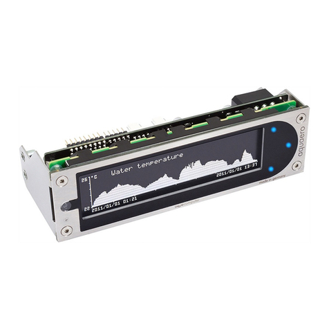
Other Aqua Computer Controllers manuals

Aqua Computer
Aqua Computer poweradjust 3 Operating manual

Aqua Computer
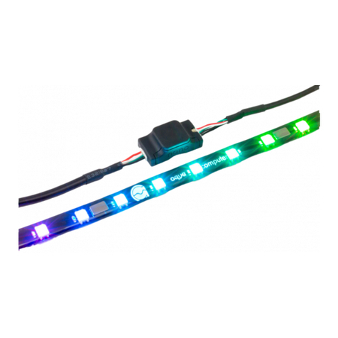
Aqua Computer farbwerk nano Operating manual

Aqua Computer
Aqua Computer farbwerk 360 Operating manual

Aqua Computer
Aqua Computer farbwerk Operating manual

Aqua Computer
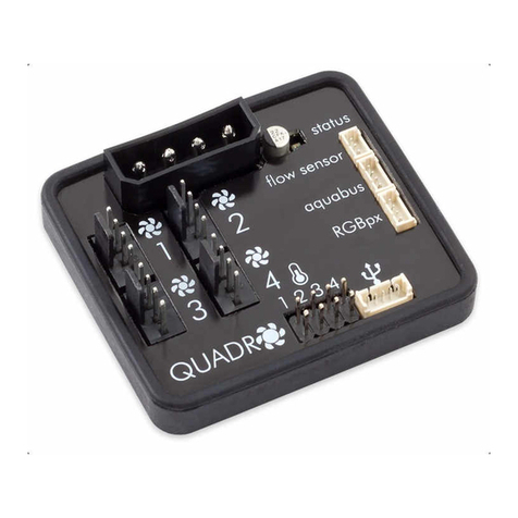
Aqua Computer QUADRO Operating manual

Aqua Computer
Aqua Computer farbwerk Operating manual

Aqua Computer
Aqua Computer OCTO Operating manual

Aqua Computer
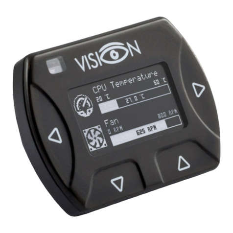
Aqua Computer VISION Operating manual

Aqua Computer
Aqua Computer aquaero 5 Operating manual