U-BRACKET
FLOAT
LIGHT
HEX NUTS HEX BOLTS
HEX BOLTS
ANGLED FLOAT
BRACKETS
U-BRACKET
FLOAT
LIGHT
FLAT BRACKET
ANGLED FLOAT
BRACKETS
FLAT
BRACKET
6Aqua Control, Inc. 60 Hz. Select Series 2 Instruction Manual
HEX BOLTS HEX NUTS
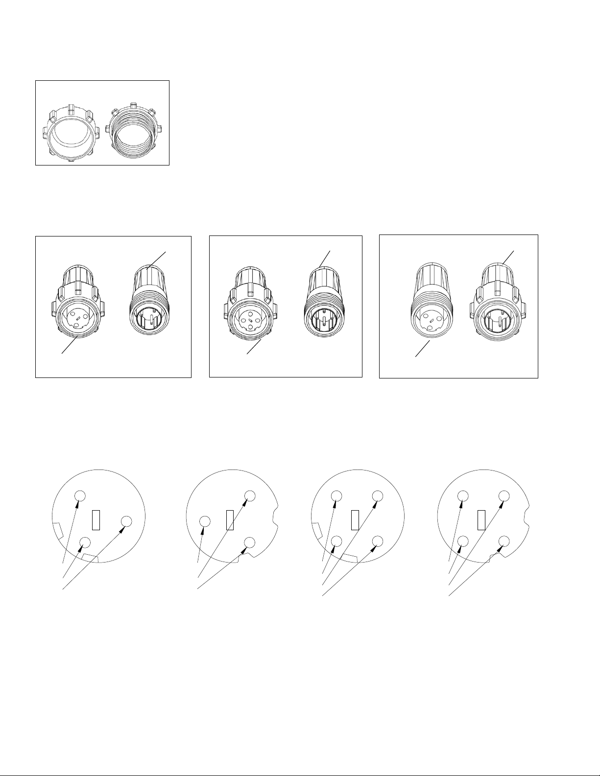
LIGHT SET ASSEMBLY
SELECT SERIES 2 FRESHWATER & SALTWATER
SELECT SERIES 2FRESHWATER
SELECT SERIES 2 SALTWATER
6. Using (2) two hex head bolts, (2) lock washers
and (2) hex nuts, attach the light bracket(s)
to the flat float bracket(s). The slots in
the light U-bracket need to be pointed up
towards the top of the unit. The light
U-bracket is shown attached at the
optimum height if the unit is floating
at the recommended depth. (See flotation
on page 12 for adding weights.) If the unit
is floating higher and is not going to be
weighted down, then the light bracket
will need to be attached lower. The
lights must be 2" below the surface of
the water when the unit is running.
4. Attach a flat float bracket to each set of
angled brackets using a hex head bolt,
lock washer and hex nut at each angled
bracket.
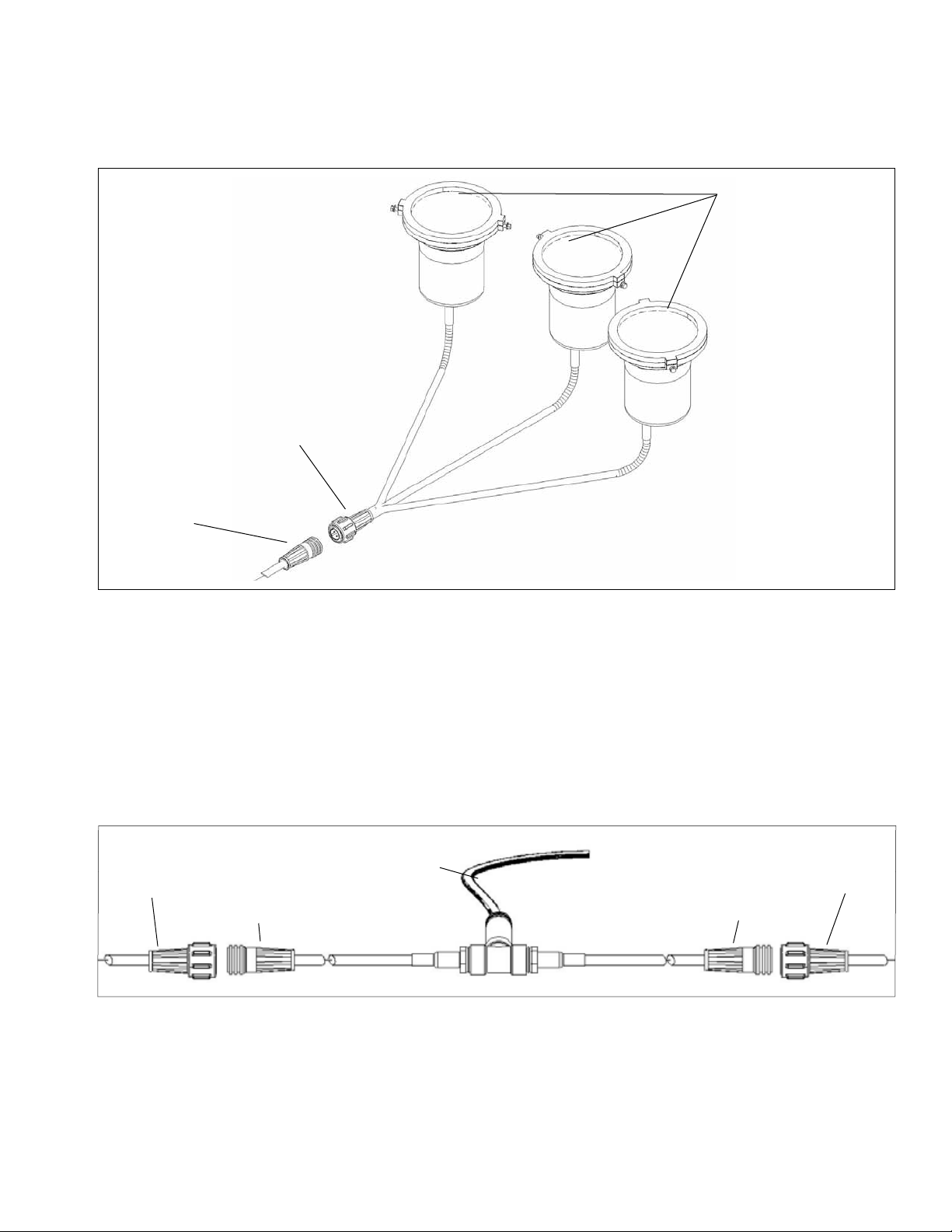
5. Take the light canisters with light brackets
attached out of the box. Stretch out the
light leads to make sure they are not tangled.
1. Open the light set box and remove the plastic
bagcontaining brackets and hardware. The
packagecontains (1) one straight float
bracket, (2) two angled float brackets, (6)
hex head bolts, (6) lock washers and (4) four
hex nuts for each light set.
2. Attach (1) one of the angled float brackets to
the top of the float at any one of the
threaded inserts. Place a lock washer on a
hex bolt and put the bolt through the
middle hole or the hole furthest from the
angle on the bracket. Thread the hex bolt
into the insertand tighten. Repeat this step
for each light in the set, placing the brackets
symmetrically around the float.
7. For saltwater units, all of the threaded
inserts in the floats are plugged by the
factory during assembly except under the
eye bolts. Remove the rubber washer and
attach the bracket by replacing the rubber
washer between the bracket and thefloat.
Plug any remaining inserts with the weight
pins or the 1/2" screws, lock washers,flat
washer and rubber washers. The rubber
washer always goes between the insert and
the hardware.
3. Attach the remaining angled float brackets
to the bottom of the float directly below
the brackets attached in step 2, using the
same hardware as in step 2. Usethesame
hole in step 3.
8. The unit is ready to be floated after
the cable connection(s) have been
made.