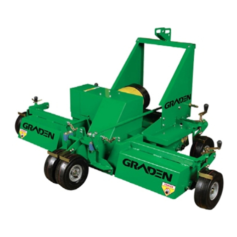
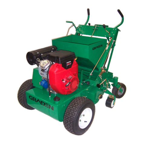
GRADEN GS04 User manual

GS04
VERTICUTTER/SCARIFIER
Owner's Manual

Graden Industries Pty. Ltd.
26-28 Scammel Street, Campbellfield
Victoria, AUSTRALIA 3061
Phone : (03) 9305 3400
Fax : (03) 9305 3995
International Phone : +61 3 9305 3400
Website : www.graden.com.au
Doc. # 053-GS04-H-AUS Issue Date: 23/01/2009

Table of Contents
1. Specifications
2. To the Owner
2.1 Preliminary Instructions
2.2 Warning Symbols
2.3 Servicing the Verticutter
3. Safety Information
3.1 General Rules
3.2 Training
3.3 Personal Protective Equipment (PPE)
3.4 Preparation
3.5 Operational Safety
3.6 Maintenance Safety
4. Controls
4.1 Pulley Clutch Handle
4.2 Lifting / Lowering Handle
4.3 Motion Lever
4.4 Engine Lever
4.5 Neutral Lever
5. Operating Instructions
5.1 Preliminary Checks
5.2 Start Up
5.3 Driving (Traversing) the Verticutter
5.4 Verticutting
5.5 Shut Down
6. Maintenance Operations
6.1 Adjustments and Settings
6.1.1 Rotor Belts
6.1.2 Gearbox Drive Belt
6.1.3 Transmission Drive Belt
6.2 Replacements
6.2.1 Blade Replacement
6.2.2 Belt Replacement
6.3 Engine Maintenance
6.4 Maintenance Schedule
7. Diagrams
8. Warning Decals

1. Specifications
Model Graden GS04 Verticutter/Scarifier
Engine Honda GX390
Power 13hp Horizontal shaft
Engine Oil 1.1 litres SAE 30W Grade
Fuel Unleaded 86 RON (minimum)
Transmission Oil SAE 30W Grade
Cutting Width 400mm
Cutting Depth 0-45mm (maximum with standard blades)
Blades Tungsten carbide tipped spring steel
Blade Size
Part Number 0048
Part Number 0381
Part Number 0049
190mm Diameter – 2mm tip (Standard)
190mm Diameter – 1mm tip (Optional)
190mm Diameter - 3mm tip (Optional)
Blade Tip Speed 2150m/min at 3600 rpm
Weight 165 kg
Width 840mm
Tyres 15 x 6.00 / 6
Tyre Pressure 95 kPa (14 psi)
Rotor Belts AP40 Gates Predator V-Belt
Gearbox Drive Belt A27 Gates V-Belt
Transmission Drive Belt A29 Gates V-Belt

2. To the Owner
Read this manual before operating the Verticutter
2.1 Preliminary Instructions
It is important that the owner completely familiarises themselves with
the contents of this manual
Keep this manual at hand as a ready reference for anybody using
the Graden GS 04 Verticutter
The designed and tested safety features of this machine are
dependent on it being operated within the limitations described in
this manual
2.2 Warning Symbols
Throughout this manual the following symbols are used to indicate
important safety issues. When either or both of these symbols are
present the operator must be aware that there is the potential to
damage equipment and/or incur serious personal injury.
WARNING
This signal denotes a potential equipment hazard :
failing to follow the instructions or procedures may
result in equipment malfunction or damage.
DANGER
This signal denotes a serious personal safety hazard :
failing to follow the instructions or procedures may
result in serious, or even fatal, injury.

2.3 Servicing the Verticutter
The Graden Verticutter has been carefully engineered and
manufactured to provide safe, dependable and effective service.
As with all mechanical equipment it requires routine cleaning and
maintenance.
Your authorised Graden representative has access to tools, genuine
spares and equipment to service any and all of your requirements.
Use only genuine Graden parts; substitute parts will void the warranty
and may not meet the safety and performance standards required for
safe and effective operation of the Verticutter.
Please record the model and serial numbers of the Verticutter in the
space provided below and quote this information when ordering parts
or communicating with Graden Industries or its’ approved
representatives.
Model Number :
Serial Number :
Date Purchased :

3. Safety Information
This manual is provided to help you operate and maintain the
Verticutter. Please read it carefully.
It has been compiled from extensive field experience and engineering
data.
In some aspects it is generalised because it is impossible to cover all
operating scenarios. However, combining the information provided in
this manual with your own increasing experience and knowledge with
the Verticutter will enable you to develop procedures suitable for your
individual needs.
The Verticutter, like most modern machinery, is constantly undergoing
development on the basis of experience and market needs. At the
time of printing, material in this manual was current but may vary due
to the aforementioned ongoing development.
Graden Industries reserve the right to change the machinery
specifications without notice.
3.1 General Rules
Direction on the machine (right or left) is determined from standing
behind the handles and facing in the direction of forward travel
When viewed from the right side the blades rotate anti-clockwise
(counter rotating to the forward rotation of the front drive wheels)
This is a precision piece of machinery with high speed cutting blades
DANGER
Keep hands and feet away from rotating parts of
the Verticutter, especially the Tungsten Carbide
tipped blades

Do not allow children to operate the machine or be near it during
its operation.
Only people who are very familiar with the rules of safe operation
should be allowed to use this machine
Only use the machine during daylight or in good artificial light
Some diagrams in this manual show the Verticutter with safety
guards removed. This is not a normal situation !
DANGER
Never operate the Verticutter with any of
the covers or safety guards removed or not
properly secured.
3.2 Training
WARNING
Read this manual completely before
beginning how to learn to use the Verticutter
Do not allow anybody to operate the machine without instruction
Know your controls and how to stop the machine and shut down
the engine quickly in an emergency
To maintain control and reduce the possibility of upset, damage or
collision, operate the machine smoothly. Avoid erratic operation
and excessive speed.

WARNING
Stay alert for holes, ditches or obstacles that
might obstruct the unit or cause it to tip over.
Be aware of the hazards associated with the engine :
Petrol is highly flammable so only use an appropriate container
Never remove the fuel cap or add fuel while the engine is
running or still hot
Never add fuel indoors and wipe up any spillages
Never run the engine in an enclosed area because exhaust
gases are toxic
DANGER
The engine uses highly flammable petroleum
fuel and produces toxic exhaust gases.
Only add fuel to, or run, the engine in the
open - never indoors.
3.3 Personal Protective Equipment (PPE)
Clothing should be reasonably snug fitting and not free flowing so as
to avoid the risk of entanglement in moving parts.
Wear sturdy footwear, preferably steel capped safety shoes or boots
Use appropriate PPE for eyes, ears and hands

DANGER
Never wear sandals, sneakers or have
bare feet when operating the Verticutter.
3.4 Preparation
Ensure all safety warnings and decals are in place and legible.
Remove any accumulated debris that might represent a fire hazard.
Ensure that the blades are in a serviceable condition and that the
rotor shaft mounting bolts are secure.
Perform any appropriate scheduled maintenance before starting
the machine.
3.5 Operational Safety
Always disengage the rotor blades before attempting to start the
Verticutter.
Always raise the rotor blades before attempting to start the
machine.
Always disengage the blades and raise them when crossing gravel,
walkways, roads, etc.. or indeed any ground which you do not wish
to cut.
DANGER
Always disengage the rotor blades and stop the
engine in any of the following situations :
leaving the machine unattended
attempting to unclog or clear the blades
making any repairs or adjustments
inspecting the unit for damage after striking
any foreign object
Always repair any damage before recommencing operation.

3.6 Maintenance Safety
DANGER
Raise blades clear of turf or surface, disengage
blades and turn off the engine before carrying
out any maintenance or servicing.
Never allow anybody to start the engine while adjustments,
maintenance or servicing are being performed.
Keep machine free of any debris
Remove debris from underneath the Verticutter after each use.
Verify that all warning labels and decals are present, visible and
legible.
Periodically check that all bolts, fasteners and catches are secure
and in safe operating condition.
After any maintenance or servicing, ensure that all guards and
safety devices are correctly installed and secure before operating
the Verticutter.
DANGER
Frequently check the rotor blades. Verify that all
the tips are in good condition.
Ensure that the blades are firmly held and there
is no slack due to damaged or worn spacers.

4. Controls
Please refer to the diagrams. All directions are given with reference to
standing behind the handles and facing in the direction of forward
travel.
4.1 Pulley Clutch Handle
This handle engages the rotor blades.
To engage the blades pull the pulley clutch handle (0031) towards you
gently and smoothly until it locks down in position against the control
panel. To disengage simply push the handle away from you. You
should engage the blades before lowering them into the turf.
4.2 Lifting/Lowering Handle
This lever lowers and raises the blades out of the turf.
The blades should be engaged before lowering them into the turf - this
avoids undue stress on the rotor belts and engine.
To lower, take the weight of the machine by the hand grips and then
slowly push the handle (0030) forward.
Gently allow the weight of the Verticutter to take the blades into the
turf.
4.3 Motion Lever
This lever controls forward and reverse motion of the Verticutter.
There is the neutral position as indicated by the sticker beside the lever
on the controls panel. Push the motion lever (0382) forwards and the
machine travels forward at a rate depending on how far the lever is
pushed.
Maximum speed corresponds to a brisk walking pace.
Pulling the lever towards you causes the machine to travel in reverse.
Maximum reverse speed is less than half of the maximum forward
speed for safety reasons.
4.4 Engine Lever
Controls rpm of the engine.
Fully forward is the idle position.
Pulling the lever towards you increases the speed of the engine.
Verticutting should be carried out at high engine speed to give high tip
speed and therefore a better cut.
4.5 Neutral Lever
This small plated lever is located on the left side of the machine,
behind the drive wheel and has two positions;
NEUTRAL : allows the machine to be pushed manually
DRIVE : engages the transmission for normal operation
The Verticutter can only be started in the NEUTRAL position.

5. Operating Instructions
DANGER
Do not operate the Verticutter until you
have completely read this manual.
5.1 Preliminary Checks
1. Clear any debris from above and underneath the machine
2. Ensure scheduled maintenance activities have been
completed.
3. Inspect belts for condition and correct tension.
4. Inspect blades for wear or damage.
5. Ensure all guards and covers are firmly fixed in place.
6. Check engine oil level ; change according to manufacturer’s
recommendations.
5.2 Start Up
1. Check that blades are disengaged - push the pulley clutch
handle all the way forward.
2. Check that the blades are in the raised position - pull
Lifting/lowering handle towards you and ensure that it locks
into position
3. Check that motion lever is in NEUTRAL position.
4. Move neutral lever (left side of machine) to NEUTRAL.
5. Turn engine switch to ON.
6. Move fuel valve lever to the ON position
7. Operate the choke lever in the direction of the arrow (i.e.
closed)
8. Slide the engine lever about 1/3 of the way toward the FAST
position
9. Pull the recoil starter grip lightly until resistance is felt, then pull
briskly. Return the starter grip gently. Repeat until engine starts.
10.Progressively slide the choke lever back to the open position
as the engine warms up.
5.3 Driving (Traversing) the Verticutter
1. Move the neutral lever (left side of machine) to DRIVE.
2. Use the motion lever to move in the desired direction. Push
the lever forward (away from you) to move forward ; pull the
lever toward you to reverse. Maximum reverse speed is
considerably slower than maximum forward speed.
3. Speed is controlled by the pressure applied to the motion
lever.

5.4 Verticutting
1. Select the depth of cut via the height adjustment knob (0218).
Normal range of cut (with standard 190mm blades) is 15mm
to 38 mm deep. One revolution of the knob is approximately
equivalent to 1mm change in the cutting depth. Clockwise
rotation of the knob means a shallower cut; anti-clockwise
means a deeper cut.
2. Increase engine speed to maximum rpm; maximum engine
speed results in a high blade tip speed and a cleaner cut.
3. Engage the blades by slowly pulling the pulley clutch handle
toward you.
4. Lower the blades into the turf by taking some of the weight of
the machine by lifting the handles and then slowly pushing
the lifting / lowering handle forward. Allow the weight of the
Verticutter to take the blades into the turf.
5. Move the motion lever forward until you are moving at the
desired speed.
6. Steer the machine in a straight line while the blades are
cutting. Trying to change direction while the blades are in the
turf may lead to a furrowing/scalping action and can put
undue stress on the blades.
7. At the end of a pass:
-move the motion lever to NEUTRAL
-raise the blades by pulling the lifting/lowering handle
towards you
-turn the Verticutter around to make your next run
-repeat from Step 4 onwards
When travelling from area to area raise the blades and disengage the
blades.
5.5 Shut Down
1. Move the motion lever to NEUTRAL
2. Raise the blades out of turf.
3. Disengage blades.
4. Traverse machine to storage/maintenance area.
5. Turn engine speed to idle.
6. Turn engine switch to OFF.
7. Slide petrol lever to OFF.
8. Clear rotor blades of any debris.
9. Clear bottom of transmission, ensuring cooling fins are not
clogged.
10.Generally clean the Verticutter, making sure that there is no
accumulated debris around the engine.

6. Maintenance Operations
The performance of certain maintenance, adjustment or repair
operations will be determined by the owner’s facilities.
Tilting of the machine for the purpose of under-deck servicing should
be done with great care.
If the Verticutter is tilted forward (i.e. pivoting over the front axle) there is
a risk that engine oil can enter the cylinder head of the engine and
transmission oil can leak from the breather located on top of the
transmission.
Either occurrence can result in expensive repairs to the machine
WARNING
Under no circumstances tilt the Verticutter
forward to carry out under-deck maintenance.
For the purpose of under-deck servicing, tilting the machine back so
that it rests on its handles is acceptable provided that the following
precautions are taken :
1. Turn the swivel wheel brackets (0035) around so that the rear
wheels are facing forward.
2. Lift the front of the machine up until the handles contact the
ground
WARNING
Heavy ! Lifting the front of the Verticutter
requires 2 people.
Never lift the front of the machine by pushing
down on the handles.
3. While holding the machine in this position securely support the
front of the machine to prevent it from falling while work is being
carried out.

4. When finished, gently lower the front of the machine back down
to the ground.
6.1 Adjustments and Settings
6.1.1 Rotor belts
Correct tension on the rotor belts is assured by the tensioning spring kit
on the pulley clutch rod. If, due to belt stretch, there is insufficient
tension on the belts to keep the rotor blades engaged and the belts
from slipping, you can tighten the nyloc nut on the end of the rod to
increase compression of the spring (5181).
6.1.2 Gearbox Drive Belt
Inadequate tension will cause slippage or lack of drive to the front
wheels; however the belt tension required to ensure successful
operation is quite low.
Remove belt guard (0294)
Loosen the bolt holding the V-idler pulley assembly (5556)
Pull the idler pulley toward the front of the machine firmly by hand
Re-tighten the holding bolt and nut.
Re-fit the belt guard.
6.1.3 Transmission Drive Belt
Excess tension places unnecessary strain on the transmission and
causes premature belt wear.
Inadequate tension will cause slippage and a lack of drive to the front
wheels; however, the tension required to ensure satisfactory operation
is relatively low
Remove the front cover (0005).
Loosen the bolt holding the under-deck V-idler pulley assembly
(5556).
Pull the idler pulley toward the front of the machine firmly by hand
and re-tighten the bolt and nut.
Re-fit the front cover.

6.2 Replacements
6.2.1 Blade replacement
1. Push the pulley clutch handle (0031) fully forward.
2. Remove the belt guard (0294)
3. Remove rotor belt retaining bracket (0066).
4. Remove rotor drive belts (5550) by easing them off the
pulley (5004) on the end of the rotor shaft (0047).
5. Loosen the grub screw from the eccentric locking collar on
the bearing (5088) at the left end of the rotor shaft and tap
the locking collar in the opposite direction to which it has
been locked. Remove the locking collar.
6. Undo the bolts holding the bearings (5025,5088) at each
end of the blade reel.
7. Allow the left bearing (5088) to slide along the rotor shaft to
provide some free movement and gently allow the blade
reel to drop free from the machine. Take care to perform
this operation with a protective layer under the machine
(old carpet is ideal) to protect the blade tips from any hard
surface.
8. Move neutral lever to NEUTRAL.
9. Lift the rear of the Verticutter away from the blade reel,
push it clear and lower the machine to the ground.
10. Slide the left end bearing (5088) from the end of the rotor
shaft (0047).
11. Remove the left Nyloc nut (5089) and rotor shaft washer
(0039) from the rotor shaft.
12. Remove blades (0048) and spacers from the shaft.
13. Replace blades and spacers as required, ensuring that
they go back on the shaft in the same direction and
configuration (i.e. counter rotating to direction of forward
travel and successive blades offset one face on the rotor
shaft.
14. Loosely re-position the bearing on the left end of the blade
reel and place the reel under the Verticutter.
15. Orient the bearings so that the grease nipples are
accessible (left bearing, nipple up; right bearing, nipple
down) and loosely bolt the blade reel in place.
16. Gently lower the machine onto the blades to locate the
blade reel in the machine and then firmly tighten the nuts
which hold the bearings in place.
17. Raise the blades.
18. Re-fit the eccentric locking collar on the left bearing of the
blade reel.
19. Re-fit rotor belts.
20. Re-fit rotor belt retaining bracket, ensuring there is
clearance between the bracket and the blade reel pulley.
21. Re-fit belt guard.

6.2.2 Belt Replacement
Note :Most of the stretch that the belts experience takes place in the
first few hours under load conditions after they have been first installed.
After fitting new belts it is advisable that the tension be checked after
the first 3 to 4 hours of operation. This is especially appropriate for the
rotor belts.
6.2.2.1 Rotor belts
1. Push the pulley clutch handle (0031) all the way forward.
2. Remove the belt guard (0294).
3. Remove the top belt guard mounts (0514 & 0515).
4. Remove the rotor belt retaining bracket (0066).
5. Loosen the clutch pulley retainer bracket (0397).
6. Remove belts by easing them off the drive pulleys.
7. Fit new belts.
8. Re-fit rotor belt retaining bracket, ensuring there is
clearance between the bracket and the blade reel pulley.
9. Re-fit the belt guard mounts (0514 & 0515).
10. Re-fit the clutch pulley retainer bracket, ensuring that
when the blades are engaged, the belts do not rub on this
retainer bracket.
11. Re-fit the belt guard.
12. Check that there is sufficient tension on the tensioning
spring when the pulley clutch handle is operated, adjust as
described in Adjustments section 6.1.1.
6.2.2.2 Gearbox Drive Belt
1. Push the pulley clutch handle all the way forward.
2. Remove the belt guard (0294).
3. Remove the upper belt guard mounts (0514 & 0515).
4. Ease rotor belts from top pulley.
5. Loosen bolt holding the V-idler pulley assembly (5556).
6. Remove gearbox drive belt (5084).
7. Fit new gearbox drive belt.
8. Re-tension idler pulley as per 6.1.2.
9. Re-fit the rotor belts.
10. Re-fit the upper belt guard mounts.
11. Re-fit the belt guard.
6.2.2.3 Transmission Drive Belt
1. Remove the front cover (0005).
2. Loosen the V-idler pulley assembly (5556) and remove it.
3 Roll the transmission drive belt (5528) downwards off the
gearbox pulley so it is sitting between the pulley and
the gearbox .
4. Rotate the belt so that the thinner profile of the belt can

slide between the top of the transmission drive pulley
(5527) and the engine base assembly (1799).
5. Now remove the belt from the gearbox pulley in the same
fashion, by rotating it to the thinner profile and sliding it
between the gearbox pulley and the engine base.
6. Fit a new belt in reverse order.
7. Re-attach the v-idler pulley assembly.
8. Tension the belt as per 6.1.3.
9. Re-fit the front cover.
6.3 Engine Maintenance
Maintenance on the Verticutter engine should be carried out as per
the manufacturer’s owner’s manual supplied with this machine.
To drain engine oil a slot has been provided in the Verticutter engine
base assembly (1799) behind the engine and immediately under the
engine oil drain plug.
1. Place a shallow (max. height 50mm) tray under the blade
reel, ensuring that the rubber exclusion strip (0347) is over the
tray.
2. Remove the oil filler cap and loosen the oil drain plug at the
bottom rear edge of the engine until oil begins to flow. Do not
completely remove the plug at this stage to avoid oil flooding
over the machine’s deck.
3. As oil flow diminishes remove the drain plug and allow oil to
drain completely.
4. Replace drain plug and re-fill engine with oil as per
manufacturer’s instructions.
5. Carefully lift rear of machine with handles and push it clear of
the oil drip tray.
6. Wipe away oil from deflector panel (0004) and rubber
exclusion strip (0347).

6.4 Maintenance Schedule
After first 4 hours :
Check tension on pulley clutch handle ; adjust as required
Check tension on gearbox pulley ; adjust as required
Check tension on transmission drive pulley ; adjust as
required
Check that the bolts on the handle assembly pivot points
are smooth in operation and not too sloppy or binding
Generally check for any loose nuts or fittings, especially
handle mounts and blade reel retaining bolts
Daily : Before Use
Check for worn, slipping or damaged belts
check for even tyre pressure (max. 95 kPa ; 14 psi)
Check for worn or damaged blades
Check for any loose nuts, bolts and fasteners
Check engine oil for correct level
Daily : After Use
Clear rotor blades of any debris
Clear bottom of transmission, especially unclog cooling fins
Clear any debris generally, especially from around engine
Every 40 Hours
Grease rotor shaft bearings
Every 6 Months
Grease all bearings
Check all belts for wear and tension ; replace if necessary
Note : Transmission fitted to this machine is a sealed
hydrostatic unit which should not require attention.
However, it is recommended that the oil level in this unit be
checked
Every 12 Months
Grease neutral lever mechanism at pivot points
Grease upper and lower motion lever mechanisms at pivot
points
Check for wear of fibre washers on handle assembly
mechanisms
Engine Maintenance
Maintain according to the manufacturer’s schedule (see
accompanying manual)
Table of contents
Other GRADEN Lawn And Garden Equipment manuals
Popular Lawn And Garden Equipment manuals by other brands

FarmTek
FarmTek 110217 quick start guide

Weed Eater
Weed Eater 1994-04 user manual

Titan Attachments
Titan Attachments ATVWC3 Operator's manual

Toro
Toro Z Master 4000 Series Operator's manual

BFG Technologies
BFG Technologies Grower Select Ultra Plastic Bench Top Assembly manual

Gecko
Gecko IT560 instruction manual