7
SAFETY RULES
• A minimum 20% of tractor and equipment weight must be on the tractor front wheels when attachments are in
transport position. Without this weight, front tractor wheels could raise up resulting in loss of steering. The weight
may be attained with front wheel weights, ballast in tires, front tractor weights or front loader. Weigh the tractor and
equipment. Do not estimate.
• Inspect and clear area of stones, branches, or other hard objects that might be thrown, causing injury or damage.
Operation
• Only engage power when equipment is at ground operating level. Always disengage power when equipment is raised
off the ground.
• Do not allow bystanders in the area when operating, attaching, removing, assembling, or servicing equipment.
• Keep bystanders away from equipment.
• Never direct discharge toward people, animals, or property.
• Do not operate equipment while under the influence of alcohol or drugs.
• Operate only in daylight or good artificial light.
• Keep hands, feet, hair, and clothing away from equipment while engine is running. Stay clear of all moving parts.
• Always comply with all state and local lighting and marking requirements.
• Never allow riders on power unit or attachment.
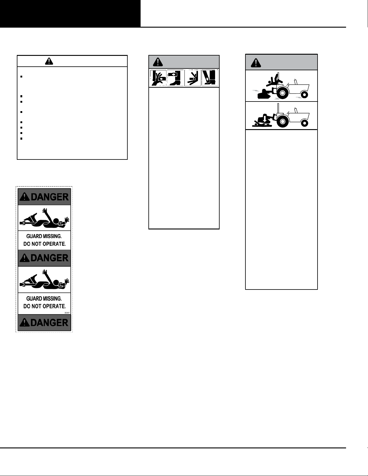
• Power unit must be equipped with ROPS or ROPS cab and seat belt. Keep seat belt securely fastened. Falling off
power unit can result in death from being run over or crushed. Keep foldable ROPS systems in “locked up” position at
all times.
• Always sit in power unit seat when operating controls or starting engine. Securely fasten seat belt, place transmission
in neutral, engage brake, and ensure all other controls are disengaged before starting power unit engine.
• Operate tractor PTO at 540 RPM. Do not exceed.
• Do not operate PTO during transport.
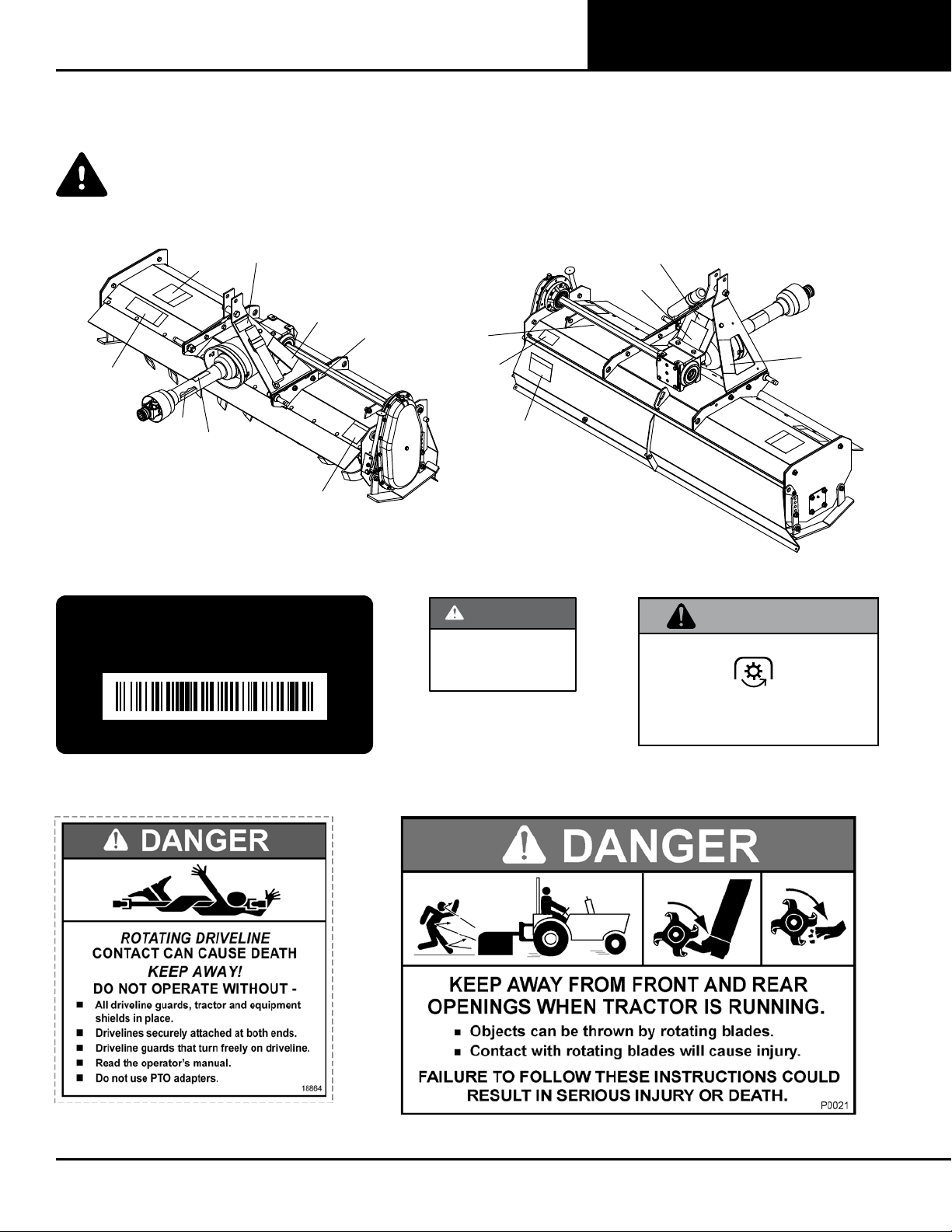
• Connect PTO driveline directly to power unit PTO shaft. Never use adapter sleeves or adapter shafts. Adapters can
cause driveline failures due to incorrect spline or incorrect operating length and can result in personal injury or death.
• Look down and to the rear and make sure area is clear before traveling in reverse.
• Use extreme care when working close to fences, ditches, other obstructions, or on hillsides.
• Do not operate or transport on steep slopes.
• Do not stop, start, or change directions suddenly on slopes.
• Use extreme care and reduce ground speed on slopes and rough terrain.
• Watch for hidden hazards on the terrain during operation.
• Stop power unit and equipment immediately upon striking an obstruction. Turn off engine, remove key, inspect, and
repair any damage before resuming operation.
• Before performing any service or maintenance, disconnect driveline from tractor PTO.
• Before dismounting power unit or performing any service or maintenance, follow these steps: disengage power to
equipment, lower the 3-point hitch and all raised components to the ground, operate valve levers to release any
hydraulic pressure, set parking brake, stop engine, remove key, and unfasten seat belt.