Gravely Promaster 260Z Owner's manual

Promaster 260Z / 272Z
Owner/Operator Manual
Models
992058 - 27hp 60”
992059 - 27hp 72”
992060 - 27hp 60”
992061 - 31hp 72”
992318 - 27hp 60”
992319 - 31hp 60”
ENGLISH
FRANÇAIS
ESPAÑOL
00160800B 12/03
Supersedes 00160800, A
Printed in USA
US Patent 6,301,864

2
Ariens Company
655 West Ryan Street
P.O. Box 157
Brillion, Wisconsin 54110-0157
USA
Telephone (920) 756-2141
Facsimile (920) 756-2407
EC DECLARATION OF CONFORMITY ISSUED BY THE MANUFACTURER –
DÉCLARATION DE CONFORMITÉ CE ÉMISE PAR LE FABRICANT –
EU-ÜBEREINSTIMMUNGSERKLÄRUNG DES HERSTELLERS – VERKLARING VAN
OVEREENSTEMMING VOOR DE EU, AFGEGEVEN DOOR DE FABRIKANT – EF
OVERENSSTEMMELSESERKLÆRING UDSTEDT AF FABRIKANTEN – DICHIARAZIONE
DI CONFORMITÀ CE RILASCIATA DAL PRODUTTORE – DECLARACIÓN DE
CONFORMIDAD CE EMITIDA POR EL FABRICANTE – EF-SAMSVARSERKLÆRING FRA
PRODUSENTEN – EG-DEKLARATIONEN OM ÖVERENSSTÄMMELSE UTFÄRDAD AV
TILLVERKAREN – VALMISTAJAN ANTAMA EY-VAATIMUSTENMUKAISUUSVAKUUTUS –
DEKLARACJA ZGODNO
Ś
CI Z PRZEPISAMI EC WYDANA PRZEZ PRODUCENTA –
DECLARAÇÃO DE CONFORMIDADE CE EMITIDA PELO FABRICANTE
We the undersigned, ARIENS COMPANY, certify that:
–
Nous, soussignés ARIENS COMPANY, certifions que :
–
Der Unterzeichnete,
ARIENS COMPANY, bescheinigt, dass:
–
Wij, de ondergetekenden, ARIENS COMPANY, verklaren dat:
–
Undertegnede, ARIENS
COMPANY, attesterer, at:
–
La sottoscritta società ARIENS COMPANY certifica che:
–
Nosotros, los abajo firmantes, ARIENS
COMPANY, certificamos que:
–
Undertegnede, ARIENS COMPANY, bekrefter at:
–
Undertecknad, ARIENS COMPANY, intygar att:
–
Allekirjoittanut, ARIENS COMPANY, vakuuttaa, että:
–
My, niżej podpisani, ARIENS COMPANY, oświadczamy, że:
–
Nós, abaixo
assinados, certificamos em nome da ARIENS COMPANY, que:
Type:
–
Type :
–
Typ:
–
Type:
–
Type:
–
Tipo:
–
Tipo:
–
Type:
–
Typ:
–
Tyyppi:
–
Typ:
–
Tipo:
Riding Rotary Lawn Mower – Tondeuse à gazon autoportée rotative – Aufsitz-Sichelmäher – Rijdende
roterende grasmaaier – Havetraktor med roterende knive – Trattorino con unità di taglio rotativa – Tractor
cortacésped giratorio – Plentraktor med rotorklipper – Rotoråkgräsklippare – Ajoleikkuri – Samobieżna
rotacyjna kosiarka trawnikowa – Tractor Cortador de Relva –
Trade Name:
–
Appellation commerciale :
–
Handelsbezeichnung:
–
Handelsnaam:
–
Firmanavn: Nome
commerciale:
–
Nombre comercial:
–
Handelsnavn:
–
Handelsbeteckning:
–
Kauppanimi: Nazwa handlowa:
–
Nome da Marca:
Gravely
Model:
–
Modèle :
–
Modell:
–
Model:
–
Model:
–
Modello:
–
Modelo:
–
Modell:
–
Modell:
–
Malli:
–
Model:
–
Modelo: 992318 992319
Cutting Width (cm):
–
Largeur de coupe (cm) :
–
Schnittbreite (cm):
–
Maaibreedte (cm):
–
Klippebredde (cm):
–
Larghezza di taglio (cm):
–
Ancho de corte (cm):
–
Klippebredde (cm)
–
: Klippbredd (cm):
–
Leikkuuleveys (cm):
–
Szerokość cięcia (cm):
–
Largura de corte (cm):
152 152
Conforms to:
–
Est conforme à :
–
Mit den Anforderungen der folgenden Richtlinien übereinstimmt:
–
Voldoet aan:
–
Er i
overensstemmelse med:
–
È conforme a:
–
Cumple con:
–
Er i samsvar med:
–
Överensstämmer med:
–
Täyttää seuraavat vaatimukset:
–
Jest zgodny z:
–
De acordo com:
98/37/EC, 89/336/EEC;
2000/14/EC Conformity Assessment Annex VI.
–
Annexe VI de l'évaluation de conformité.
–
Konformitätsbewertung, Anhang VI.
–
Bijlage VI voor beoordeling van overeenstemming.
–
Vurdering af overensstemmelse Anneks VI.
–
Annesso VI della valutazione di conformità.
–
Anexo VI de la evaluación de la conformidad.
–
Samsvarsvurdering etter vedlegg VI.
–
Bedömning av överensstämmelse Bilaga VI.
–
Vaatimustenmukaisuuden arviointi, liite VI.
–
Dodatek VI, Ocena zgodno
ś
ci.
–
Anexo VI da Avaliação de Conformidade.
Representative Measured Sound Power Level (Lwa)
–
Niveau de
puissance acoustique représentatif mesuré (Lwa)
–
Repräsentativer
gemessener Geräuschpegel (Lwa)
–
Representatief gemeten
geluidsniveau (Lwa)
–
Repræsentativt, målt støjeffektniveau (Lwa)
–
Livello di potenza sonora rappresentativo rilevato (Lwa)
–
Nivel de
potencia acústica representativo medido (Lwa)
–
Representativt
målt lydeffektnivå (Lwa)
–
Representativ uppmätt ljudnivå (Lwa)
–
Tyypillinen mitattu äänitehotaso (Lwa)
–
Zmierzony reprezentatywny
poziom mocy akustycznej (Lwa)
–
Nível de Potência de Som
Medido Representativo (Lwa)
Guaranteed Sound Power Level (Lwa) – Niveau de puissance
acoustique garanti (Lwa) – Garantierter Geräuschpegel (Lwa) –
Gegarandeerd geluidsniveau (Lwa) – Garanteret støjeffektniveau
(Lwa) – Livello di potenza sonora garantito (Lwa) – Nivel de potencia
acústica garantizado (Lwa) – Garantert lydeffektnivå (Lwa) –
Garanterad uppmätt ljudnivå (Lwa) – Taattu äänitehotaso (Lwa) –
Gwarantowany reprezentatywny poziom mocy akustycznej (Lwa) –
Nível de Potência de Som Garantido (Lwa) –
992318: 104 dBA992318: 105 dBA
992319: 104 dBA992319: 105 dBA

3
CE Sound and Vibration – Bruits et vibrations CE – CE Geräusch- und Vibrationswerte – CE Geluid en
trilling – CE støj og vibration – Livello sonoro e vibrazioni CE – Sonido y vibración CE – CE-lyd og
-vibrasjon – CE ljudnivå och vibrationer – CE, melu ja tärinä – CE Dźwięku i Wibracji – Som e Vibração CE
– (Ref. EN836-2001)
Notified Body – Organisme notifié – Zertifizierungsstelle –
Aangemeldeinstantie– Bemyndigetorgan–Organismonotificato –
Organismo notificado – Teknisk kontrollorgan – Anmält organ –
Ilmoitettu laitos – Organ zaświadczający – Organismo –
Certificador
SNCH
11, Route de Luxembourg
L-5230 Sandweiler
Philip J. Smucker:
Quality and Conformance Manager (Keeper of Technical File)
–
Responsable de la qualité et de la conformité des produits
(Dépositaire de la fiche technique)
–
Manager Qualitätssicherung
und Konformität (Archivar der technischen Akte)
–
Kwaliteits- en
normalisatiemanager (Beheerder van technische bestand)
–
Chef for
kvalitet og overensstemmelse (Indehaver af tekniske data)
–
Responsabile della qualità e della conformità del prodotto
(Depositario del file tecnico)
–
Gerente de calidad y conformidad
(Depositario del archivo técnico)
–
Kvalitet- og samsvarsansvarlig
(innehaver av teknisk fil)
–
Chef för kvalitet och
produktöverensstämmelse (Innehavare av tekniska data)
–
Laadusta
ja vaatimustenmukaisuudesta vastaava johtaja (Teknisen tiedoston
haltija)
–
Kierownik do spraw jakości i zgodności
(Przechowujący DokumentacjęTechniczną)
–
Gestor de Qualidade
e Conformidade (Zelador de Arquivos Técnicos)
Ariens Company
Brillion, WI 54110-0157 USA
Signature
–
Signature
–
Unterschrift
Handtekening
–
Underskrift
–
Firma Firma
–
Signatur
–
Namnteckning Allekirjoitus
–
Podpis
–
Assinatura
11/24/2003
Date
–
Date
–
Datum
Datum
–
Dato
–
Data
Fecha
–
Dato Datum
–
Päiväys Data
–
Data
Model:
–
Modèle :
–
Modell:
–
Model:
–
Model:
–
Modello:
–
Modelo:
–
Modell: Modell:
–
Malli:
–
Model:
–
Modelo: 992318 992319
Oper. Ear Sound Pressure (Lpa) in dBA – Pression acoustique aux oreilles de l’opérateur (Lpa) en dBA –
Geräuschpegel am Ohr des Bedieners (Lpa) in dBA – Geluidsdruk bij het oor van de gebruiker (Lpa) in dBA –
Strøjtryk ved brugerens øre (Lpa) målt i dBA– Pressione sonora all’orecchio dell’operatore (Lpa) in dBA – Presión
de sonido en el oído (Lpa) in dBA – Lydtrykk ved førerens øre (Lpa) inn dBA – Ljudeffekt vid förarens öron (Lpa) i
dBA – Kuljettajan korvaan kohdistuva äänenpaine (Lpa), dBA – Robocze ciśnienie akustyczne na uchu (Lpa) w
decybelachA – Oper. Pressão do Som no Ouvido (Lpa) em dBA 90 90
Vibration Measure (m/sec2) at Operator
–
Mesure des vibrations (m/s2) au niveau de l’opérateur
–
Vibration
(m/s2) an des Bedieners
–
Gemeten trilling bij (m/sec2)
–
Vibrationsmålinger (m/s2) ved brugerens
–
Vibrazioni
percepite dall’operatore (m/sec2)
–
Medida de vibración (m/seg2) en el operador
–
Vibrasjonsmåling (m/s2) ved
førerens
–
Vibrationsmått (m/s2) vid förarens
–
Tärinä (m/s2) kuljettajan
–
Pomiar wibracji (m/sec2) u operatora
–
Medida de Vibração (m/seg.2) no Operador
Hands – Mains – Hände –De handen van degebruiker –Hænder – Mani – Manos –Hender – Händer – Käsissä
– Ręce – Mãos X
Y
Z
3.2
0.5
0.9
<2.5
<2.5
<2.5
Feet – Pieds – Füße – De voeten van de gebruiker – Fødder – Piedi – Pies – Føtter – Fötter – Jaloissa – Stopy
– Pés X
Y
Z
0.2
0.2
0.8
0.5
0.5
0.7
Seat – Siège – Sitz – De bestuurdersplaats – Sæde – Sedile – Asiento – Sete – Säte – Istuimella – Siedzenie –
Assento X
Y
Z
0.3
0.3
0.5
0.5
0.5
0.6

GB - 4
Safety . . . . . . . . . . . . . . . . . . . . . . . . . . . . . . . . . . . . . . . . 5
Assembly . . . . . . . . . . . . . . . . . . . . . . . . . . . . . . . . . . . . 10
Controls and Features. . . . . . . . . . . . . . . . . . . . . . . . . . 11
Operation . . . . . . . . . . . . . . . . . . . . . . . . . . . . . . . . . . . . 12
Maintenance Schedule . . . . . . . . . . . . . . . . . . . . . . . . . 15
Service and Adjustments . . . . . . . . . . . . . . . . . . . . . . . 17
Storage. . . . . . . . . . . . . . . . . . . . . . . . . . . . . . . . . . . . . . 28
Troubleshooting . . . . . . . . . . . . . . . . . . . . . . . . . . . . . . 28
Accessories . . . . . . . . . . . . . . . . . . . . . . . . . . . . . . . . . . 29
Service parts . . . . . . . . . . . . . . . . . . . . . . . . . . . . . . . . . 29
Specifications . . . . . . . . . . . . . . . . . . . . . . . . . . . . . . . . 30
Warranty. . . . . . . . . . . . . . . . . . . . . . . . . . . . . . . . . . . . . 31
THE MANUAL
Before operation of unit, carefully and completely read your
manuals. The contents will provide you with an
understanding of safety instructions and controls during
normal operation and maintenance.
All reference to left, right, front, or rear are given from
operator sitting in operation position and facing the direction
of forward travel.
MODEL AND SERIAL NUMBERS
When ordering replacement parts or
making service inquiries, know the Model
and Serial numbers of your unit and
engine.
Numbers are located on the product
registration form in the unit literature
package. They are printed on a serial
number label, located on the frame of
your unit.
Record Unit Model and Serial numbers here.
Record Engine Model and Serial numbers here.
UNAUTHORIZED REPLACEMENT PARTS
Use only Gravely replacement parts. The replacement of any
part on this vehicle with anything other than a Gravely
authorized replacement part may adversely affect
performance, durability, or safety of this unit. Gravely
disclaims liability for any claims or damages, whether
warranty, property damage, personal injury or death arising
out of the use of unauthorized replacement parts.
DISCLAIMER
Gravely reserves the right to discontinue, make changes to,
and add improvements upon its products at any time without
public notice or obligation. The descriptions and
specifications contained in this manual were in effect at
printing. Equipment described within this manual may be
optional. Some illustrations may not be applicable to your
unit.
PRODUCT REGISTRATION
The Gravely dealer must register the product at the time of
purchase. Registering the product will help the company
process warranty claims or contact you with the latest
service information. All claims meeting requirements during
the limited warranty period will be honored, whether or not
the product registration card is returned. Keep a proof of
purchase if you do not register your unit.
Customer Note: If the dealer does not register your
product, please fill out, sign, and return the product
registration card to Gravely.
DELIVERY
Customer Note: If you have purchased this product without
complete assembly and instruction by your retailer, it is your
responsibility to:
1. Read and understand all assembly instructions in this
manual. If you do not understand or have difficulty
following the instructions, contact your nearest Gravely
Dealer for assistance. Make sure all assembly has been
properly completed and safety interlock system works
properly.
TABLE OF CONTENTS
INTRODUCTION
Transfer
model & serial
number label
from product
registration
here.
Figure 1
Serial Number Label
OC0191
© Copyright 2003 Ariens Company

GB - 5
NOTE: To locate your nearest Gravely Dealer, call
1-800-472-8359 or go to www.gravely.com on the internet.
2. Understand all Safety Precautions provided in the
manuals.
3. Review control functions and operation of the unit. Do
not operate unit unless all controls function as described
in this manual.
4. Review recommended lubrication, maintenance, and
adjustments.
5. Fill out Product Registration Card and return the card to
Ariens Company or go to www.gravely.com.
SAFETY ALERT SYMBOL
These are safety alert symbols. They mean:
• ATTENTION!
• YOUR SAFETY IS INVOLVED!
When you see this symbol:
• BECOME ALERT!
• OBEY THE MESSAGE!
SIGNAL WORDS
The safety alert symbols above and signal words below are
used on decals and in this manual.
Read and understand all safety messages.
NOTATIONS
NOTE: General reference information for proper operation
and maintenance practices.
IMPORTANT: Specific procedures or information required to
prevent damage to unit or attachment.
PRACTICES AND LAWS
Practice usual and customary safe working precautions, for
the benefit of yourself and others. Understand and follow all
safety messages. Be alert to unsafe conditions and the
possibility of minor, moderate, or serious injury or death.
Learn applicable rules and laws in your area.
REQUIRED OPERATOR TRAINING
Original purchaser of this unit was instructed by the seller on
safe and proper operation. If unit is to be used by someone
other than original purchaser (loaned, rented, or sold),
ALWAYS provide this manual and any needed safety
training before operation.
SAFETY DECALS AND LOCATIONS
ALWAYS replace missing or damaged safety decals. See
figure 2 for safety decal locations.
1. DANGER! TO AVOID SERIOUS INJURY OR
DEATH
WARNING: Improper assembly or adjustments can
cause serious injury.
SAFETY
WARNING: This cutting machine is capable of
amputating hands and feet and throwing objects.
Failure to observe the safety instructions in the
manuals and on decals could result in serious
injury or death.
Slopes are a major factor related to loss-of-control
and tip-over accidents. Operation on all slopes
requires extra caution.
Tragic accidents can occur if the operator is not
alert to the presence of children. Never assume
that children will remain where you last saw them.
Gasoline is extremely flammable and the vapors
are explosive, handle with care.
Disengage attachment, stop unit and engine,
remove key, engage parking brake, and allow
moving parts to stop before leaving operator’s
position.
DANGER: IMMINENTLY HAZARDOUS
SITUATION! If not avoided, WILL RESULT in death
or serious injury.
WARNING: POTENTIALLY HAZARDOUS
SITUATION! If not avoided, COULD RESULT in
death or serious injury.
OL1253
OL3900
CAUTION: POTENTIALLY HAZARDOUS
SITUATION! If not avoided, MAY RESULT in minor
or moderate injury. It may also be used to alert
against unsafe practices.
Read Operator’s Manual.
Keep children and others away from unit while
operating.
Never direct discharge toward other people.
Thrown objects can cause injury.
OL1801
OL4370
OL0910

GB - 6
2. DANGER!
Look down and behind before and while
backing.
Never carry children.
Go up and down slopes, not across.
DO NOT operate on slopes over 17°.
• If machine stops going uphill, stop blade and back
down slowly.
• Avoid sudden turns.
• Keep safety devices (guards, shields, switches, etc.)
in place and working.
• Check interlock system per manual before use.
• Understand location and function of all controls.
OL4460
OL4470
OL4480
17°
MAX
OL4450
• Never allow operation by untrained persons.
Always keep feet and hands away from
rotating parts.
Always stand clear of discharge area. Do not
direct discharge toward other people.
Keep people away from unit while operating.
Shut off engine, remove key, and read manual
before you adjust or repair unit.
NO STEP! Always keep feet away from
rotating parts.
OL3030
OL0910
OL3292
OL4010
OL4420
DANGER/PELIGRO
07731400D
DANGER/PELIGRO
07731400D
WARNING/AVERTISSEMENT/ADVERTENCIA
Do not operate mo er
unless guards are in
operating position or
bagger is attached.
Ne jamais utiliser
la tondeuse sans
protecteur sur le
canal d'ejection ou
sans le bac monte.
No operar segadora a
menos que las defensas
esten en posicion de
operacion o el
recogedor este fijo.
07742300B
Risque de blessures - ne pas sapprocher des pièces en
mouvement.
Evitar lesiones - Mantenerse alejado de las piezas giratorias.
Avoid injury - Stay clear of rotating parts.
07735200C
DANGER / PELIGRO
Read the operator's manual.
Keep children and others away from unit while
operating.
Never direct discharge toward other people.
Thrown objects can cause injury.
Loo down and behind before and while bac ing.
Never carry children.
Go up and down slopes, not across.
If machine stops going uphill, stop blade and
bac down slowly.
Avoid sudden turns.
Keep safety devices (guards, shields, switches,
etc.) in place and wor ing.
Chec interloc system per manual before use.
Understand location and function of all controls.
Never allow operation by untrained persons.
Leer el manual del operador.
Mantenga la unidad alejada de los niños u otras personas
cuando esté en funcionamiento.
Nunca dirija la descarga hacia otras personas, ya que los
objetos lanzados pueden provocar lesiones.
Antes y durante retroceso mirar hacia abajo y detras.
Nunca monten niños.
Suba y baje pendientes, no transversalmente.
Si la maquina se detiene subiendo cuesta, desactive la
cuchilla y baje lentamente.
Evite viradas subitas.
Mantenga artefactos de seguridad (defensas, protectores,
interruptores, etc.) en su lugar y trabajando.
Verifique en el manual el sistema de engranar antes de usar.
Tenga conocimiento de funciones y localizaciones de todos
los controles.
Never allow operation by untrained persons.
TO AVOID SERIOUS INJURY OR DEATH POUR EVITER LES BLESSURES GRAVES OU LA MORT PARA EVITAR DAÑOS SERIOS O LA MUERTE
Lire le manuel d'utilisation.
Éloigner les engants et tout autre personne pendant le fonctionnement de la
machine.
Ne jamais décharger directement en direction de quelquun. Des particules
projetées peuvent provoquer des blessures.
Regardez derriere et sur les cotes lorsque vous reculez.
Ne transportez jamais dénfant.
Tondez toujours de haut en bas et inversement jamais le long des pentes.
Si la machine sárrete en montee. Debrayez la lame et redescendez
doucement.
Evitez les virages brusques.
Maintenez toujours en place tous les elements de securite (protecteurs,
interrupteurs, etc.).
Controlez le bon fonctionnement des interrupteurs de securité avant
utilisation tel q'uindiqué dans le manuel d'utilisation.
Comprenez bien la fonction et la situation de chacun des leviers et boutons
de commande.
Never allow operation by untrained persons.
DANGER / PELIGRO
MAX
17
07734700D
2
4
1
5
Figure 2 OF1624
3
6
2

GB - 7
3. WARNING!
4. HOT SURFACES!
5. DANGER!
6. DANGER!
SAFETY RULES
Read, understand, and follow all safety practices in
Owner/Operator Manual before beginning assembly. Failure
to follow instructions could result in personal injury and/or
damage to unit.
ALWAYS remove key and/or wire from spark plug before
assembly. Unintentional engine start up can cause death or
serious injury.
Complete a walk around inspection of unit and work area to
understand:
• Work area • Your unit • All safety decals
Determine which attachments are needed and can be used
safely.
Inspect unit before each use for: missing or damaged decals
and shields, correctly operating safety interlock system, and
deterioration of grass catchers. Replace or repair as
needed.
ALWAYS check overhead and side clearances carefully
before operation. ALWAYS be aware of traffic when
operating along streets or curbs.
Keep children and people away.
Keep children out of work area and under watchful care of a
responsible adult.
Keep area of operation clear of all toys, pets, and debris.
Thrown objects can cause injury.
Check for weak spots on docks, ramps or floors. Avoid
uneven work areas and rough terrain. Stay alert for hidden
hazards or traffic.
DO NOT operate near drop-offs, ditches, or embankments.
Unit can suddenly turn over if a wheel is over the edge of a
cliff or ditch, or if an edge caves in.
Data indicates that operators, age 60 and above, are
involved in a larger percentage of riding mower related
injuries. These operators should evaluate their ability to
operate the riding mower safely enough to protect
themselves and others from serious injury.
Read the entire Owner/Operator manual and other training
material. If the operator or the mechanic cannot read the
manual, it is the owner’s responsibility to explain it to them.
Only the user can prevent and is responsible for accidents or
injuries occurring to themselves, other people or property.
Only trained adults may operate or service unit. Training
includes actual operation.
Local regulations may restrict the age of the operator.
NEVER allow children to operate or play on or near unit. Be
alert and shut off unit if children enter area.
NEVER operate unit after or during the use of medication,
drugs or alcohol. Safe operation requires your complete and
unimpaired attention at all times.
DO NOT wear loose clothing or jewelry and tie back hair that
may get caught in rotating parts.
Wear adequate outer garments.
NEVER wear open sandals or canvas shoes during
operation. Wear adequate safety gear, protective gloves and
footwear.
Wear proper footwear to improve footing on slippery
surfaces.
Always wear safety goggles or safety glasses with side
shields when operating mower.
Moving parts can cut or amputate fingers or a hand. Wrap
blade(s) or wear gloves to service. On multiblade mowers,
rotation of one blade will cause all blades to rotate.
NEVER place your hands or any part of your body or
clothing inside or near any moving part while unit is running.
ALWAYS keep hands and feet away from all rotating parts
during operation. Rotating parts can cut off body parts.
ALWAYS keep body and hands away from pin holes or
nozzles which eject hydraulic fluid under pressure.
DO NOT touch parts which are hot. Allow parts to cool.
ALWAYS keep hands and feet away from all pinch points.
Fumes from the engine exhaust can cause death or serious
injury. DO NOT run engine in an enclosed area. Always
provide good ventilation.
Read, understand, and follow all instructions in the manual
and on the machine before starting.
Understand:
• How to operate all controls
• The functions of all controls
• How to STOP in an Emergency
Always stand clear of discharge area.
Do not operate mower unless guards are in
operating position or bagger is attached.
DO NOT touch parts which are hot from
operation. ALWAYS allow parts to cool.
AVOID INJURY. Stay clear of rotating parts.
AVOID INJURY. Stay clear of rotating fan.
OL4430
OL3320
OD0061
OL4730
OL4740

GB - 8
• Braking and steering characteristics
• Turning radius and clearances
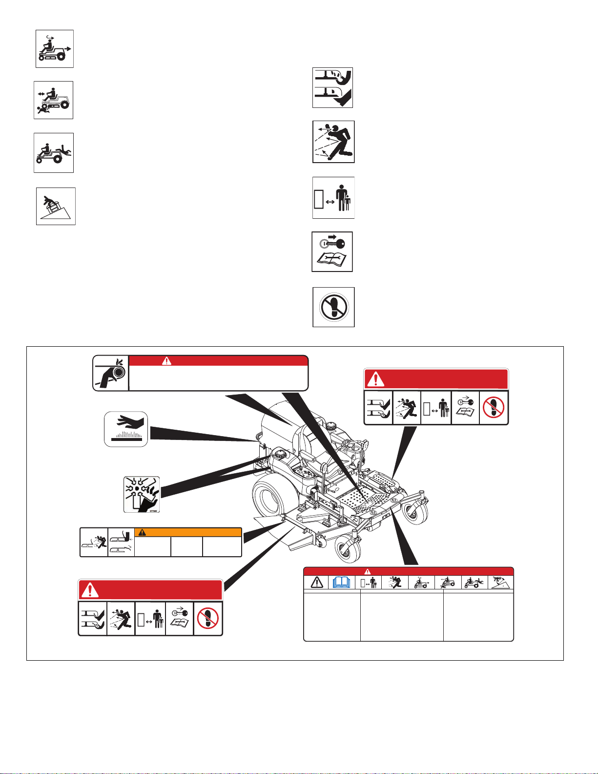
Keep safety devices or guards in place and functioning
properly. NEVER modify or remove safety devices.
Do not operate without either entire grass catcher or the
discharge guard in place.
Stop engine before removing grass catcher or unclogging
chute.
Ensure Safety Interlock System is functioning properly. DO
NOT operate unit if safety interlock is damaged or disabled.
Start and operate unit only when seated in operator’s
position. Steering control levers must be in neutral, PTO
disengaged and parking brake set when starting engine.
Use care when approaching blind corners, shrubs, trees or
other objects that may obscure vision.
Dust, smoke, fog, etc. can reduce vision and cause an
accident. Mow only in daylight or good artificial light.
Avoid slippery surfaces. Always be sure of your footing.
DO NOT mow on wet grass. Reduced traction could cause
sliding and effect the machine’s stability.
Watch for traffic when operating near or crossing roadways.
Never carry passengers.
DO NOT try to stabilize the machine by putting your foot on
the ground.
Never direct discharge towards persons or property that may
be injured or damaged by thrown objects. Use extreme
caution on gravel surfaces.
Always stand clear of the discharge area.
ALWAYS disengage PTO, stop unit and engine, remove
key, engage parking brake and allow moving parts to stop
before leaving operator’s position.
Never engage PTO while raising attachment or when
attachment is in raised position.
DO NOT operate at too fast a rate. DO NOT change engine
governor settings or over-speed engine. Slow down before
turning.
DO NOT operate in reverse unless absolutely necessary.
ALWAYS look down and behind before and while backing.
Stop and inspect equipment if you strike an object or if there
is an unusual vibration. Repair, if necessary, before
restarting. Never make adjustments or repairs with the
engine running.
Mower blades are sharp and can cut you. Wrap the blade(s)
or wear gloves, and use extra caution when servicing them.
NEVER weld or straighten mower blades.
Rotation of one blade may cause rotation of the other
blades.
Take all possible precautions when leaving unit unattended.
Shut off engine. Remove wire from spark plug and secure it
away from spark plug.
ALWAYS remove key to prevent unauthorized use.
Know the weight of loads. Limit loads to those you can
safely control and the unit can safely handle.
Disengage PTO when attachment is not in use. ALWAYS
turn off power to attachment when travelling, crossing
driveways, etc.
Mow up and down slopes, not across them.
DO NOT operate on slopes of more than 17 degrees.
Use of a Rollover Protection System (ROPS) is
recommended for slope operation. See Attachments and
Accessories.
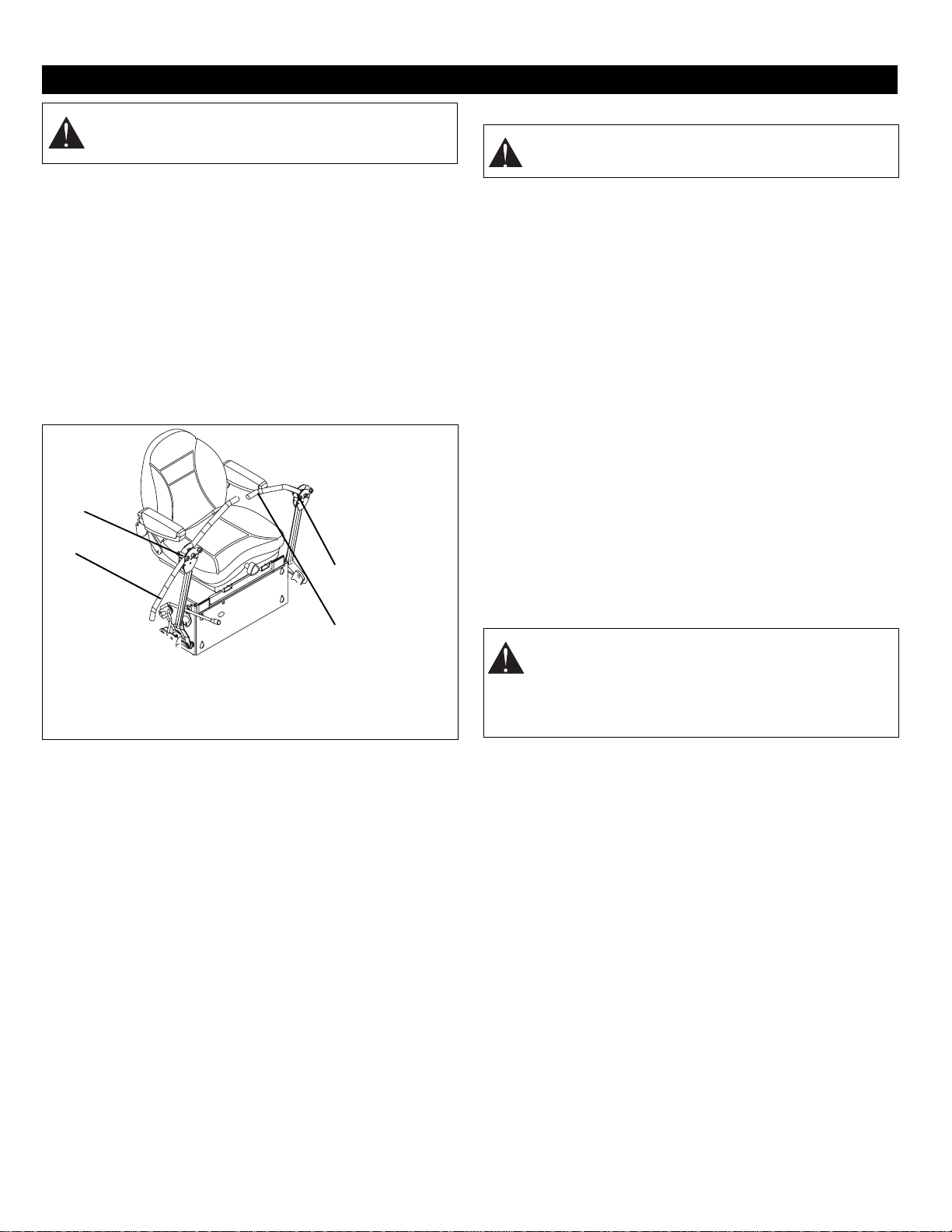
Always wear a seat belt when operating unit using a
Rollover Protection System (ROPS).
Keep all movements on the slope slow and gradual. Do not
make sudden changes in speed or direction.
Avoid starting or stopping on the slope. If tires lose traction,
disengage the blades and proceed slowly straight down the
slope.
If you cannot back up a slope or you feel uneasy on it, do not
mow it.
DO NOT park on slopes unless necessary. When parking on
slope always chock or block wheels. Always set parking
brake.
Use a slow speed. Tires may lose traction on slopes even
though the brakes are functioning properly.
Do not bypass transmission when on a slope.
Tow only with a machine that has a hitch designed for
towing. Do not attach towed equipment except at the hitch
point.
Follow the manufacturer’s recommendations for weight
limits for towed equipment and towing on slopes.
NEVER allow children or others in or on towed equipment.
On slopes, the weight of the towed equipment may cause
loss of control.
Travel slowly and allow extra distance to stop.
Use extra care when loading or unloading unit onto trailer or
truck.
Secure unit chassis to transport vehicle. NEVER secure
from rods or linkages that could be damaged.
DO NOT transport machine while engine is running.
ALWAYS turn off power to attachment and shut off fuel
when transporting unit.
Keep unit free of debris. Clean up oil or fuel spills.
This product is equipped with an internal combustion type
engine. DO NOT use unit on or near any unimproved,
forest-covered or brush covered land unless exhaust system
is equipped with a spark arrester meeting applicable local,
state or federal laws. A spark arrester, if it is used, must be
maintained in effective working order by operator.
Fuel is highly flammable and its vapors are explosive.
Handle with care. Use an approved fuel container.
NO smoking, NO sparks, NO flames. ALWAYS allow engine
to cool before servicing.
NEVER fill fuel tank when engine is running or hot from
operation.
NEVER fill or drain fuel tank indoors.

GB - 9
Replace fuel cap securely and clean up spilled fuel.
Never fill containers inside a vehicle or on a truck or trailer
bed with a plastic liner. Always place containers on the
ground away from your vehicle before filling.
When practical, remove gas-powered equipment from the
truck or trailer and refuel it on the ground. If this is not
possible, then refuel such equipment on a trailer with a
portable container, rather than from a gasoline dispenser
nozzle.
Keep the nozzle in contact with the rim of the fuel tank or
container opening at all times until fueling is complete. Do
not use a nozzle lock-open device.
If fuel is spilled on clothing, change clothing immediately.
Avoid Electric Shock. Objects contacting both battery
terminals at the same time may result in injury and unit
damage. DO NOT reverse battery connections.
Reverse connections may result in sparks which can cause
serious injury. Always connect positive (+) lead of charger to
positive (+) terminal, and negative (-) lead to negative (-)
terminal.
ALWAYS disconnect negative (-) cable FIRST and positive
(+) cable SECOND. ALWAYS connect positive (+) cable
FIRST, and negative (-) cable SECOND.
Explosive Gases from battery can cause death or serious
injury. Poisonous battery fluid contains sulfuric acid and its
contact with skin, eyes or clothing can cause severe
chemical burns.
No flames, No sparks, No smoking near battery.
ALWAYS wear safety glasses and protective gear near
battery. Use insulated tools.
DO NOT TIP battery beyond a 45° angle in any direction.
ALWAYS keep batteries out of reach of children.
Battery posts, terminals and related accessories contain
lead and lead compounds, chemicals known to the State of
California to cause cancer and reproductive harm. Wash
hands after handling.
ALWAYS block wheels and know all jack stands are strong
and secure and will hold weight of unit during maintenance.
Release pressure slowly from components with stored
energy.
NEVER attempt to make any adjustments to unit while
engine is running (except where specifically recommended).
Stop engine, remove key or spark plug wire and wait for all
moving parts to stop before servicing or cleaning.
Check parking brake operation frequently. Adjust and
service as required.
ALWAYS maintain unit in safe operating condition.
Damaged or worn out muffler can cause fire or explosion.
Maintain or replace safety and instruction labels, as
necessary.
NEVER store unit with fuel in fuel tank, inside a building
where any ignition sources are present.
Shut off fuel and allow engine to cool completely before
storing in closed area or covering unit.
Clean grass and debris from unit, especially from around
muffler and engine, to help prevent fires.
For extended storage, shut off fuel and clean unit
thoroughly. See engine manual for proper storage.
Lower cutting deck unless a positive mechanical lock is
used.
Use only attachments or accessories designed for your unit.
Check all hardware at regular intervals, especially blade
attachment bolts. Keep all hardware properly tightened.
Check attachment components frequently. If worn or
damaged, replace with manufacturer’s recommended parts.

GB - 10
Unpack Unit
Remove unit and all other components from shipping container.
Open bypass valves (see Moving Unit Manually on page 14).
Push unit from container onto a level surface. Close bypass
valves.
Prepare Seat
Remove nuts from seat studs in hood frame. Peel off paper
backing from foam tape and place between hood frame and
chassis. Lift and rotate seat onto hood frame. Secure with nuts.
Install Steering Levers
Remove bolts and spacers from steering rod. Flip steering
levers up into operating position. Reinstall spacers, bolts,
and nuts. Tighten hardware securely (figure 3).
Install Deflector
Remove, reverse, and reinstall deflector and mounting
bracket.
Check Tire Pressure
See Specifications on page 30.
Check Engine Oil
Refer to Engine Manual.
Check Hydraulic Oil
See Checking Hydraulic Oil Level on page 25.
Check Coolant Level
See Checking Coolant Level on page 26.
Fill Fuel Tank
See Filling Fuel Tank on page 14.
Connect Battery
Place hood in the full service position (see Service Positions
on page 17). Connect negative (–) battery cable to battery.
(see Battery Removal and Installation on page 18 and
perform steps 2 through 4 in the installation section).
Level Mower Deck
See Leveling the Mower Deck on page 20.
Check Safety Interlock System
See Check Safety Interlock System on page 10.
Check Function of All Controls
Ensure unit runs and performs properly.
ASSEMBLY
WARNING: AVOID INJURY. Read and understand
the entire Safety section before proceeding.
1. Steering Lever in
Shipping Position
2. Spacers and Hardware
3. Steering Lever in
Operation Position
1
2
3
2
OF3224
Figure 3
WARNING: Deflector must pivot freely. DO NOT
overtighten pivot bolts.
WARNING: Safety interlock system failure and
improper operation of unit can result in death or
serious injury. Test this system each time unit is
operated. If this system does not function as
described, do not operate until repairs are made.

GB - 11
1. Hood
2. Fuel Tanks
3. Steering Levers
4. Mower Lift Lever
5. Seat Adjustment Lever
6. Seat Suspension Adjustment Knob
7. Fuel Valve
8. Parking Brake Lever
9. Axle Lock
10.Height of Cut Indicator
11.Tie-Down Lugs
12.Cylinder Stops
13.Mower Deck with Chute Deflector
14.Belt Cover
15.Foot Board Latch
16.Cylinder Stop Storage Post
17.Headlights
18.PTO (Power Take-Off) Switch
19.Ignition Switch
20.Oil Pressure Light
21.Battery Light
22.Water Temperature Gauge
23.Throttle Lever
24.Choke Control (992058, 059)
25.Fuel/Water Separator Light (992060, 061, 318, 319)
26.Hour Meter
27.Headlight Switch
28.Hood Latch
CONTROLS AND FEATURES
Figure 4 OF3223
12
3
4
5
6
7
8
9
10
11
12
13141516
17
18
19
20
21
22
23
24
25
26
27
11
2
28

GB - 12
CONTROLS AND FEATURES
SeeFigure 4 for all Controls and Features locations.
Safety Interlock System
Perform the following tests to ensure safety interlock system
is working properly. If unit does not perform as stated contact
your Gravely dealer for repairs.
NOTE: For all models, when parking brake is engaged,
steering levers are locked in neutral. For models 992318
and 319, engine must not start or run with hood raised.
Parking Brake Interlock System
With parking brake engaged, steering levers must be locked
in neutral.
With parking brake disengaged, engine must not start and
engine must shut off if operator leaves seat.
Ignition Switch (992058, 059)
Operate ignition switch with removable
ignition key. Ignition switch has three
positions: Off (1), On (2), and Start (3).
See Starting and Shutting Off the
Engine on page 14 for detailed
instructions on how to start engine.
Ignition Switch (992060, 061, 318, 319)
Operate ignition switch with
removable ignition key. Ignition
switch has four positions:
Thermo Start (1), Off (2), On (3),
and Start (4). See Starting and
Shutting Off the Engine on
page 14 for detailed instructions
on how to start engine.
Choke Control (992058, 059)
Use to start a cold engine. Push choke lever
forward to choke engine. Pull choke lever to
the rear when engine gets warm.
Power Take-Off (PTO) Switch
Engages and disengages mower blades.
On (1) – Engages mower blades.
Off (2) – Disengages mower blades.
Throttle Lever
Changes the speed of engine.
Fast (1) – Increases engine speed.
Slow (2) – Decreases engine speed.
Oil Pressure Light
Lights up red when engine oil pressure is
low. Check engine oil level and add if
necessary (refer to Engine Manual).
Hour Meter
Records total number of hours engine has been
run.
NOTE: Hour meter will continue to run if ignition
key is left in the run position with the engine
turned off.
OPERATION
WARNING: AVOID INJURY. Read and understand
the entire Safety section before proceeding.
WARNING: Safety interlock system failure and
improper operation of unit can result in death or
serious injury. Test this system each time unit is
operated. If this system does not function as
described, do not operate until repairs are made.
Test Steering
Levers PTO Parking
Brake Engine
STARTING INTERLOCK
1 Neutral Off Engaged Start
2 Neutral On Engaged Doesn’t Start
3 Neutral Off Disengaged Doesn’t Start
OPERATING INTERLOCK (ENGINE ON)
4* Neutral On Engaged Shuts Off
5* Neutral Off Disengaged Shuts Off
6* Neutral Off Engaged On
* Operator lifts off seat.
START
RUN
OFF 1
2
3OF1750
START
RUN
OFF
T
HERMO
START
1
2
3
4
OF0563
OF1680
OE0261
1
2
OF170
0
2
1
OG0601
OF1890

GB - 13
Water Temperature Gauge
Indicates temperature of coolant.
Refer to Engine Manual for normal
operating range.
Headlight Switch
Turns headlights on and off.
Off (1)
On (2)
Fuel Valve Controls fuel flow from left tank (1) or right
tank (2).
NOTE: There is no Off (3) position.
Fuel/Water Separator Light (992060, 061, 318, 319)
Indicates when fuel/water separator filter needs to be
replaced (refer to Engine Manual).
Battery Light
Lights up when starting engine and indicates that battery has
a full charge. If battery light does not light up, battery needs
charging (see Charging the Battery on page 18).
Steering Levers Controls speed,
directional control, and
stopping unit.
• Reverse (1) – Pull
both steering levers
backward.
• Forward (2) – Push
both steering levers
forward.
• Left (3) – Pull left steering lever back or push right
steering lever forward or a combination of both.
• Right (4) – Pull right steering lever back or push left
steering lever forward or a combination of both.
To stop, return both steering levers to neutral.
NOTE: Steering levers are mechanically locked in neutral
whenever parking brake is engaged.
NOTE: Aggressive turning can scuff or damage lawns.
ALWAYS keep both wheels rotating when making sharp
turns. DO NOT make turns with inside wheel completely
stopped. To obtain minimum turning radius, slowly reverse
inside wheel while moving outside wheel slowly forward.
Parking Brake Lever
Engages (2) and disengages (1)
parking brake.
Mower Lift Lever
Raises and lowers mower deck.
To lower (1) – Move mower lift lever
forward.
To raise (2) – Move mower lift lever
rearward.
Cylinder Stops
Ensures the same cutting height after raising mower deck to
clear an obstacle. Cylinder stops are stored on a post behind
hydraulic lift cylinder and come in two sizes: 11/32 in. and
11/16 in. (8.73 mm and 17.5 mm).
1. Remove cylinder stops from post and snap onto lift
cylinder rod.
2. Push lift lever forward until cylinder rests against
cylinder stops.
Seat Adjustment Lever
Pull lever out and slide seat to desired position. Release
lever to lock seat into position.
Seat Suspension Adjustment Knob
To make seat more firm turn knob clockwise. To make seat
less firm turn knob counterclockwise.
Axle Locks
For a solid front axle, install axle locks on front axle. For a
pivoting front axle, remove axle locks from front axle and
store on unit (figure 5).
°F
170 195 220
280
100
40
80 100140
WATER
TEMP
°C
OF330
5
OF3313
2
1
RIGHT
TANK
LEFT
TANK
OFF
OF1881
1
2
3
077348A
1
3
2
4
OF174
0
1
2
OF1700
1
2
OF3308
1
2
3
Figure 5
1. Axle Lock Storage
2. Axle Locks Installed
3. Front Axle

GB - 14
FILLING FUEL TANK
To add fuel to fuel tank:
1. Place unit in an open or well-ventilated area.
2. Shut off engine and allow to cool.
3. Clean fuel cap and surrounding area to prevent dirt from
entering fuel tank.
4. Remove fuel cap.
IMPORTANT: Refer to Engine Manual for correct type and
grade of fuel. See Specifications on page 30 for fuel tank
capacity.
5. Fill fuel tank to within 1 in. (2.54 cm) below bottom of
filler neck.
6. Replace fuel cap and tighten.
7. Clean up any spilled fuel.
STOPPING IN AN EMERGENCY
Bring steering levers back to neutral, set parking brake, and
turn off engine.
STARTING AND SHUTTING OFF THE ENGINE
NOTE: DO NOT operate starter more than 15 seconds per
minute, as overheating and damage can occur. If engine will
not start, see Troubleshooting on page 28 or refer to Engine
Manual.
NOTE: PTO must be disengaged and parking brake
engaged prior to starting engine.
Gas Models (992058, 059)
To start:
1. Insert ignition key.
2. Move throttle control lever to middle position.
NOTE: If engine is cold, move choke control to the on
position. Once engine has started and is warmed up, move
choke control to the off position. If engine is warm, do not
use choke. 3. Turn ignition key to Start (3) position.
If engine does not start in five seconds,
release ignition key, wait, and then
repeat. Once engine has started,
ignition key will return to the Run (2)
position.
To shut off:
1.Disengage PTO.
2. Set parking brake.
3. Turn ignition key to Off (1) position.
Diesel Models (992060, 061, 318, 319)
To start:
1. Insert ignition key.
2. Move throttle control lever to
middle position.
NOTE: If temperature is 32 ºF
(0 ºC) or below, turn ignition key
to Thermo Start (1) position for
15 seconds.
3. Turn ignition key to Start (4) position. If engine does not
start in five seconds, release ignition key, wait, and then
repeat. Once engine has started, release ignition key
and ignition key will return to the Run (3) position.
To shut off:
1. Disengage PTO.
2. Set parking brake.
3. Turn ignition key to Off (2) position.
OPERATING MOWER
1. Start engine.
2. Move throttle lever three-fourths of the way up to fast.
IMPORTANT: Never engage PTO if mower is plugged with
grass or other material.
3. Engage PTO to engage mower blades.
4. Move throttle lever to fast.
5. Release parking brake.
6. Use steering levers to move the unit.
7. Disengage PTO to stop mower blades.
PARKING THE UNIT
1. Move steering levers to the neutral position. Shut off
PTO.
2. Move throttle lever to the slow position.
3. Engage parking brake.
MOVING UNIT MANUALLY
IMPORTANT: Never tow unit.
WARNING: AVOID INJURY. Read and understand
the entire Safety section before proceeding.
START
RUN
OFF 1
2
3OF1750
START
RUN
OFF
T
HERMO
START
1
2
3
4
OF0563
1. Right Bypass Valve Lever
2. Left Bypass Valve Lever
3. Hydraulic Reservoir
4. Battery
5. Hydrostatic Transmission
1
2
OF3221
3
4
5
Figure 6

GB - 15
1. Place hood in the full service position (see Service
Positions on page 17).
2. Turn right and left bypass valve levers counterclockwise
1/2 turn (figure 6).
3. Disengage parking brake.
4. Push unit to desired location.
5. Engage parking brake.
6. Turn bypass valve levers clockwise 1/2 turn.
TRANSPORTING UNIT
ALWAYS shut off engine, set parking brake, and remove key
when transporting unit on a truck or trailer. Tie unit down
securely. Do not tie down by linkages, guards, cables or
other parts that may be damaged.
FOR BEST PERFORMANCE
Cut grass when it is dry.
Keep mower blades sharp.
Keep mower deck properly leveled.
Adjust anti-scalp rollers to prevent scalping.
Do not set height of cut too low. For very tall grass, mow
twice.
Do not travel too fast.
Mow with the engine set at full throttle.
When mulching, only remove 1/3 of grass length per cutting.
Discharge clippings into areas already cut.
Vary cutting pattern with each mowing.
Do not allow grass or debris to collect inside of mower deck.
Clean after each use.
Proper maintenance can prolong the life of unit. The
following chart shows the recommended service schedule.
More frequent service may be required due to working
conditions (heavy loads, high ambient temperatures, dusty
conditions, or airborne debris).
See the maintenance instructions in Engine Manual for
additional information.
WARNING: Do not bypass transmission when on a
slope.
MAINTENANCE SCHEDULE
WARNING: AVOID INJURY. Read and understand
the entire Safety section before proceeding.
Interval Task Action
Each Use
Check Safety Interlock WARNING: Safety interlock system failure and improper operation of unit
can result in death or serious injury. Test this system each time unit is
operated. If this system does not function as described, do not operate until
repairs are made (see Safety Interlock System on page 12).
Check Parking Brake
Interlock System See Parking Brake Interlock System on page 12.
Check Parking Brake Engage parking brake. Push unit. If unit rolls adjust parking brake (see Parking
Brake Adjustment on page 24).
Check Hydraulic Oil Level See Checking Hydraulic Oil Level on page 25.
Check Tires See Specifications on page 30 for correct tire pressure.
Clean Unit Clean engine, battery, seat, mower deck, etc. of all dirt and debris. Do not use
solvents, hard cleaners, or abrasives.
NOTE: Protect painted surfaces with automotive type wax.
Follow Engine Manual
Maintenance Schedule Perform scheduled engine maintenance. Refer to Engine Manual for detailed
instructions.
Check Cooling System IMPORTANT: Do not use high-pressure water to clean radiator. High-pressure
water will damage radiator.
Check cooling system for dirt and debris in radiator screen, hoses, fan, etc. Refer to
Engine Manual for detailed instructions.
Every 25
Hours
Check Mower Blades Ensure mower blade hardware is tightened to 115 – 125 lbf-ft. (156 – 169 N•m).
Check mower blades for wear. Sharpen or replace mower blades as needed (see
Sharpening Mower BladE on page 19).
Every 50
Hours Lubricate Front Axle and
Pivot Points Oil all pivot points, pin connections and apply grease to front axle grease zerk (see
Lubricating Unit on page 18).

GB - 16
Every100
Hours
Clean Battery Keep battery and battery terminals clean (see Cleaning the Battery on page 18).
Check Fasteners Check mower blade mounting hardware and all other fasteners. Replace missing or
damaged fasteners. Tighten all nuts and bolts to their correct torque value.
Check Belts Replace worn or deteriorated belts.
• Check mower drive belt (see Mower Drive Belt Removal on page 22 for mower
drive belt location).
• Check PTO belt (see PTO Belt Removal on page 21 for PTO belt location).
• Check transmission belt (see Transmission Belt Removal on page 22 for
transmission belt location).
• Check radiator fan belt (refer to Engine Manual).
Every200
Hours Change Coolant (992058,
059) See Changing Coolant on page 26.
Every400
Hours
Change Coolant (992060,
061, 318, 319) See Changing Coolant on page 26.
Grease Front Axle Castor
Pivots Repack front axle caster pivots (see Lubricating Unit on page 18).
Every500
Hours Change Hydraulic Oil and
Filter See Hydraulic Oil System on page 25.
Interval Task Action

GB - 17
Gravely Dealers will provide any service which may be
required to keep your unit operating at peak efficiency.
Should engine service be required, it can be obtained from a
Gravely Dealer or engine manufacturer’s authorized service
center.
SERVICE POSITIONS
IMPORTANT: Place unit on a flat level surface. ALWAYS
shut off engine, set parking brake, and remove ignition key.
Ensure unit is secure and will not tip over. When a lift is
used, strap and clamp unit to the lift.
1. Place steering levers in neutral position and set parking
brake.
2. Unhook hood latches. Firmly grasp hood frame handle
and lift to the desired service position (figure 7).
Daily Service Position: Place hood prop rod into service
slot. Ensure prop rod is engaged in service slot properly.
Full Service Position: Slowly release hood after seat
contacts foot board. Use care and be sure of your footing.
Do not step on mower deck.
3. When service is complete, lower hood, and secure with
hood latches.
SERVICE AND ADJUSTMENTS
WARNING: AVOID INJURY. Read and understand
the entire Safety section before proceeding.
CAUTION: HOT SURFACES may result in injury.
DO NOT touch engine or drive parts which are hot
from operation. Allow parts to cool before servicing.
CAUTION: When opening hood, use care to
properly engage hood prop rod into service slot. Be
sure footing is secure to accomodate weight shift of
hood when rotating to full service position.
OF3225
1. Hood in Daily Service
Position
2. Hood in Full Service
Position
3. Battery
4. Hood Prop Rod
5. Service Slot
6. Hood Latches
7. Hood Frame Handle
1
Figure 7
7
5
4
3
2
6

GB - 18
LUBRICATING UNIT
IMPORTANT: Wipe front axle grease zerk and two front
axle castor pivots clean before and after lubrication.
NOTE: Use Stens Mix Hi-Temp Grease or equivalent
(part number 00036700).
SERVICING THE BATTERY
NOTE: Unit comes equipped with a maintenance-free
battery that requires no regular maintenance except
cleaning the terminals.
Battery Removal and Installation
Remove
1. Place hood in full service position (see Service Positions
on page 17).
2. Disconnect negative (–) cable first, then positive (+)
cable (figure 9).
3. Remove battery hold-down bracket and battery from
unit.
Install
1. Install battery on unit with battery hold-down bracket.
2. Connect positive (+) cable first, then negative (–) cable.
3. Coat terminals with dielectric grease or petroleum jelly.
4. Close hood (see Service Positions on page 17).
Cleaning the Battery
1. Disconnect negative (–) cable first, then positive (+)
cable.
2. Clean battery cable ends and terminals with wire brush.
Rinse with a weak baking soda solution.
3. Connect positive (+) cable first, then negative (–) cable.
4. Coat terminals with dielectric grease or petroleum jelly.
Charging the Battery
Follow First Aid directions for contact with battery fluid.
•External Contact: Flush with water.
•Eyes: Flush with water for at least 15 minutes and get
medical attention immediately!
•Internal Contact: Drink large quantities of water. Follow
with Milk of Magnesia, beaten egg or vegetable oil. Get
medical attention immediately!
• In case of internal contact, DO NOT induce vomiting!
IMPORTANT: DO NOT fast charge. Charging at a higher
rate will damage or destroy battery. ALWAYS follow
information provided on battery and battery charger. Contact
battery manufacturer and battery charger manufacturer for
detailed instructions.
1. Remove battery from unit (see Battery Removal and
Installation on page 18).
2. Place battery on bench or other well-ventilated area.
3. Connect positive (+) lead of charger to positive (+)
terminal, and negative (–) lead to negative (–) terminal.
4. Charge battery according to the instructions from battery
charger manufacturer and battery manufacturer.
Item Lubrication Location Interval
1 Repack Front Axle Caster Pivot 400
hours
2 Grease Front Axle Grease Zerk 50
hours
Oil All Pivot Points, Pin
Connections 50
hours
Figure 8
WARNING: AVOID INJURY. Read and understand
the entire Safety section before proceeding.
WARNING: Battery posts, terminals and related
accessories contain lead and lead compounds,
chemicals known to the State of California to cause
cancer and reproductive harm. Wash hands after
handling.
OF1792
1
2
1
WARNING: FROZEN BATTERIES CAN
EXPLODE and result in death or serious injury. DO
NOT charge a frozen battery. Let battery thaw
before charging.
1. Battery
2. Negative (–) Terminal
3. Negative (–) Cable
4. Positive (+) Terminal
5. Positive (+) Cable
12
4
OF3227
Figure 9
3
5

GB - 19
5. Install battery on unit (see Battery Removal and
Installation on page 18).
Jump Starting Battery
Unit used for jump starting should have a 12 volt battery with
at least 500 cold cranking amperes, and a negatively
grounded system.
IMPORTANT: Ensure battery is not frozen. If fluid is frozen,
remove battery from unit and allow battery to thaw before
charging.
1. Connect positive (+) jumper cable to positive terminal of
discharged battery (figure 9).
2. Connect the other end of the same jumper cable to
positive (+) terminal of booster battery.
3. Connect one end of the second jumper cable to
negative (–) terminal of booster battery.
4. Make the final jumper cable connection to engine block
or the furthest ground point away from the discharged
battery.
NOTE: If engine will not start after several tries, unit or
battery may need service.
5. Start engine.
6. After engine starts, leave cables connected for one to
two minutes.
7. Disconnect jumper cables in reverse order of
installation.
8. Operate unit as normal to charge battery.
MOWER BLADE REMOVAL
NOTE: If mower is used under sandy soil conditions, replace
mower blades when air lifts become eroded through at ends
(figure 11).
Removal (Figure 10)
1. Block mower blades to prevent rotation.
2. Remove bolts, washers, and mower blades from spindle
shafts.
Installation (Figure 10)
1. Install mower blades, washers, and bolts on spindle
shafts.
2. Tighten bolts to 115-125 lbf-ft (156-169 N•m).
SHARPENING MOWER BLADE
NOTE: If mower is used under sandy soil conditions, replace
mower blades when air lifts become eroded through at ends
(figure 11).
1. Remove mower blade from unit.
Discard mower blade if (figure 11):
• More than 1/2 in. (1.27 cm) of metal is removed.
• Air lifts become eroded.
• Blade is bent or broken.
2. Sharpen mower blade by removing an equal amount of
material from each end of mower blade. DO NOT
change angle of cutting edge or round the corner of
mower blade.
WARNING: Make sure cables are clear of any
moving engine parts before starting engine.
CAUTION: Mower blades are sharp and can cut
you. Wrap mower blades or wear gloves, and use
extra caution when servicing.
Figure 10 OF3312
11. Mower Blade
2. Spindle Shaft
3. Washer
4. Bolt
2
3
4
CAUTION: DO NOT sharpen mower blades whjile
on unit. An unbalanced mower blade will cause
excessive vibration and eventual damage to unit.
Check mower blade balance before reinstalling
blades.
NEVER weld or straighten bent blades.
Figure 11 OF3310
12
DO NOT Sharpen To This Pattern
Sharpen To This Pattern
1. Air Lift Erosion
Area 2. Cutting Edge
DISCARD
if more
than 1/2 in.
(1.27 cm)

GB - 20
3. Check mower blade balance. Slide mower blade on an
unthreaded bolt. A balanced blade should remain in a
horizontal position. If either end of mower blade moves
downward, sharpen the heavy end until blade is
balanced.
4. Install mower blade on unit.
ANTI-SCALP ROLLER ADJUSTMENT
Anti-scalp rollers are set at the factory for typical mowing
height, but can be adjusted for high or low cutting conditions
(figure 12).
Rollers are intended to prevent lawn scalping, not to control
cutting height.
For a very high cutting height, set rollers in their lowest
position on bracket.
For a very low cutting height, set rollers in their highest
position on bracket.
All rollers should be set at the same height.
MOWER DECK REMOVAL
Removal (Figure 13)
NOTE: Only remove PTO belt from electric clutch.
1. Remove PTO belt from electric clutch (see PTO Belt
Removal on page 21).
2. Remove link chains from mower lift arms.
3. Remove mounting pin and mower mounting arms from
mower deck.
4. Slide mower deck out from under unit.
Installation (Figure 13)
1. Slide mower deck under unit.
IMPORTANT: To prevent damage to PTO belt, mounting
pins MUST be installed as shown in figure 13.
2. Install mower mounting arms on mower deck with
mounting pins.
3. Install link chains on mower lift arms.
4. Install PTO belt on electric clutch (see PTO Belt
Removal on page 21).
5. Level mower deck (see Leveling the Mower Deck on
page 20).
LEVELING THE MOWER DECK
These adjustments should be made on a level surface with
tires inflated to the correct air pressure.
Mower deck is leveled from side to side with the slots where
four chains fasten to mower mounting brackets. Mower deck
is leveled from front to rear by adjusting rod running down
each side of frame (figure 14).
1. Shut off engine. Set parking brake. Remove ignition key.
2. Raise mower deck and insert 3 in. (7.6 cm) tall blocks to
support deck.
3. Lower deck onto blocks so chains are slack.
4. Measure from bottom of mower blade end to ground.
5. Set hydraulic lift cylinder so cut of height reads the same
as blade height measurement.
WARNING: Prior to adjusting anti-scalp rollers,
shut off engine, set parking brake, and remove
ignition key.
DANGER: MOVING PARTS can cut or amputate
body parts. ALWAYS wait for moving parts to stop
before performing maintenance or service.
OF3160
Figure 12
Highest
Roller
Position
Lowest
Roller
Position
Of0316
Figure 13
1
1. Mower Lift Arm
2. Link Chain
3. Mower Deck
4. Mower Mounting Arm
5. Mounting Pin
6. PTO Mower Belt
2
4
2
6
5
3
Other manuals for Promaster 260Z
3
This manual suits for next models
7
Table of contents
Other Gravely Lawn And Garden Equipment manuals

Gravely
Gravely Pro-QXT Tractor 985910 User manual

Gravely
Gravely 8000 Series User manual

Gravely
Gravely Pro Vac 1060 User manual

Gravely
Gravely 892051 User manual

Gravely
Gravely CONVERTIBLE 7.6 User manual

Gravely
Gravely Pro-Turn 100 User manual

Gravely
Gravely 885914 User manual

Gravely
Gravely D User manual

Gravely
Gravely Tratch-O-Matic Owner's manual

Gravely
Gravely Rapid XZ 27hp Kohler User manual